

Page 1

User's Guide
Black-and-White Raster Plotter
LP-1020
LP-1020L
Read this User's Guide to use the plotter safely and
properly. Keep this manual in a place where you
can quickly access it at any time.
Seiko I Infotech Inc.
Page 2

Page 3

U00107742300 November 2007
U00107742301 December 2007
©Seiko I Infotech 2007
Reprinting of this manual without permission is prohibited.
The content of this manual may be changed without notice.
D-SCAN is a registered trademark of Seiko Instruments, Inc.
Ethernet is a registered trademark of Xerox, Inc.
HP is a registered trademark of Hewlett-Packard (U.S.A.)
MICRO CADAM is a trademark of CADAM, Inc. (U.S.A.)
Athlon is a trademark of Advanced Micro Device, Inc.
Intel, Pentium and Core are registered trademarks or a trademark of Intel Corporation.
This equipment has been tested and found to comply with the limits for a Class A digital device,
pursuant to Part 15 of the FCC Rules. These limits are designed to provide reasonable protection
against harmful interference when the equipment is operated in a commercial environment.
This equipment generates, uses, and can radiate radio frequency energy and, if not installed and
used in accordance with the instruction manual, may cause harmful interference to radio
communications. Operation of this equipment in a residential area is likely to cause harmful
interference in which case the user will be required to correct the interference at his own expense.
Durch die Kennzeichnung dieses Produktes mit dem CE-Zeichen erklärt Seiko den folgenden
Direktiven der Europäischen Union zu entsprechen (mit Wirkung vom siehe Datum):
Januar 1996:- EG-Direktive 73/23/EEC ergänzt durch EG-Direktive 93/68/EEC, Angleichung der
Gesetze der einzelnen Mitgliedsstaaten bezüglich Geräten mit niedriger Betriebsspannung.
Januar 1996:- EG-Direktive 89/336/EEC, Angleichung der Gesetze der einzelnen Mitgliedsstaaten
bezüglich elektromagnetischer Kompatibilität.
Den vollständigen Text dieser Erklärung einschließlich der Definition der entsprechenden
Direktiven sowie der jeweiligen Standards erhalten Sie von Ihrem Seiko Colorgrafx Systems
Kundendienst oder Ihrem Seiko Engineering Systems Kundendienst.
This Perchlorate warnig applies ONLY in California USA
“Perchlorate Material - special handling may apply,
See www.dtsc.ca.gov/hazardouswaste/perchlorate”
Page 4

CE Marking
It is legally mandatory for products distributed or sold in the EU to bear a CE Mark that
indicates compliance with requirements set forth in EC directives for the particular
product. These directives set the scope of machinery subjected to the specific directive.
Our LP-1020 complies with the EMC Directive (2004/108/EC) and Low Voltage Directive
(2006/95/EC).
For inquiries concerning CE Marks:
Seiko Instruments Europe S.A
European Head Office
Avenue de Messidor 198, 1180, Brussels, Belgium
TEL: +32 (0) 2 346 62 74
FAX: +32 (0) 2 347 52 68
Page 5

Introduction
Thank you for purchasing our LP-1020/1020L Black-and-White Raster
Plotter (hereafter referred to as “this device”).
This manual explains the overall device operations, functions and
operation method under the premise that installation of the device has
been completed.
Before using this device, please read the “Safety Precautions” so that you
may operate this device safely and correctly. Keep this manual in a place
where you can quickly access it at any time.
This device employs either one of the following feeders: 1-roll paper
feeder for standard sheet drawings with output up to 2.5 m, or 2-rolls
paper feeder for long sheet drawings with output up to 10 m.
This manual explains how to use the 2-rolls paper feeder devices, but also
accomodates the 1-roll paper feeder devices.
i
Page 6
Safety Precautions
The following symbols are used in this manual to ensure the proper use of
the plotter and to prevent the plotter from being damaged.
Please follow these guidelines:
WARNING
CAUTION
Example of symbols:
Warnings must be followed carefully to avoid serious
bodily injury or death.
Cautions must be observed to avoid damage to your
equipment and bodily injury.
This symbol ( ) denotes items that require special care while
executing a certain procedure or operation.
This symbol ( ) denotes items that are forbidden.
This symbol ( ) denotes items you should follow to prevent
accidents or injury.
ii
Page 7
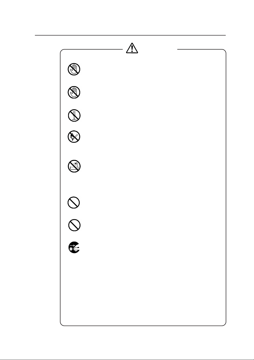
Warning
DO NOT touch any of the parts inside the plotter with a "HIGH
VOLTAGE" label attached as it may result in electric shock.
DO NOT touch any of the parts inside the plotter with a "HIGH
TEMPERATURE" label attached as it may result in severe burns.
DO NOT disassemble or modify the plotter. DO NOT repair the plotter
by yourself. Doing so may cause fire, electric shock or other accidents.
DO NOT throw the toner cartridge or waste toner bottle into fire or
place them near heat as they could explode or catch fire leading to
serious accidents and/or bodily injury.
NEVER use the plotter in a place of extreme humidity or any place
where it can possibly be splashed by any liquids. If any liquids get into
the plotter, it could lead to fire, electric shock, or other serious
accidents.
DO NOT allow metal to touch the internal parts of the plotter. Doing so
may cause fire, electric shock, or other accidents.
DO NOT disconnect or connect the power cable with wet hands. Doing
so may lead to electric shock.
Power OFF the plotter and unplug the power cable from the power
outlet in any of the following cases:
◆ When putting your hands inside the plotter.
◆ Smoke, strange noise or smells erupt from the plotter.
◆ A piece of metal or any liquid touches the internal parts or slots of
the plotter.
◆ An error requiring service from a service center occurs.
Using the plotter in any manner other than for which it was designed may
cause accidents or fire.
iii
Page 8
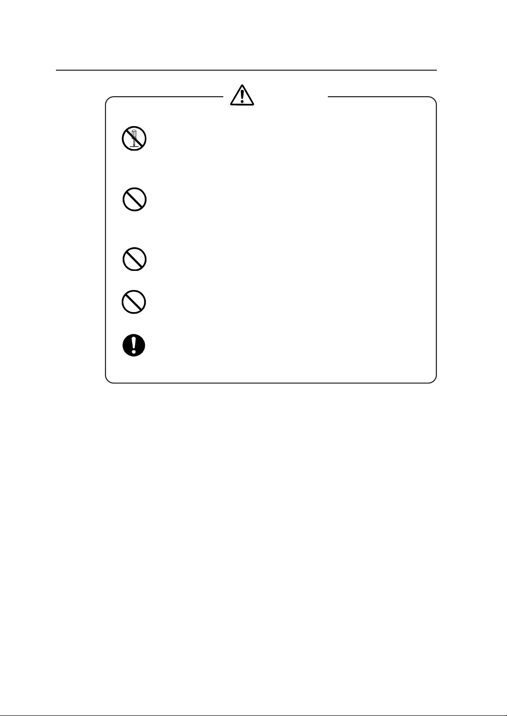
Caution
DO NOT disassemble, modify the toner cartridge. If toner gets on your
skin or clothes, wash off the affected area immediately with soap and
water.
Handle the toner cartridge with extreme care. Should any toner get into
your eyes, do not rub them, flush them immediately with water, and see
a physician immediately.
Handle the paper rolls with care because they are very heavy. Dropping
them may lead to personal injury.
Use care when cutting the paper rolls with a scissors or knife during
installation.
DO NOT unplug the electric cable by pulling on the cable. Doing so
may cause the cable to fray or break which could lead to electric shock
and/or fire.
In order to ensure the safe operation of the plotter heed all of the cautions
and warnings contained throughout this manual.
iv
Page 9
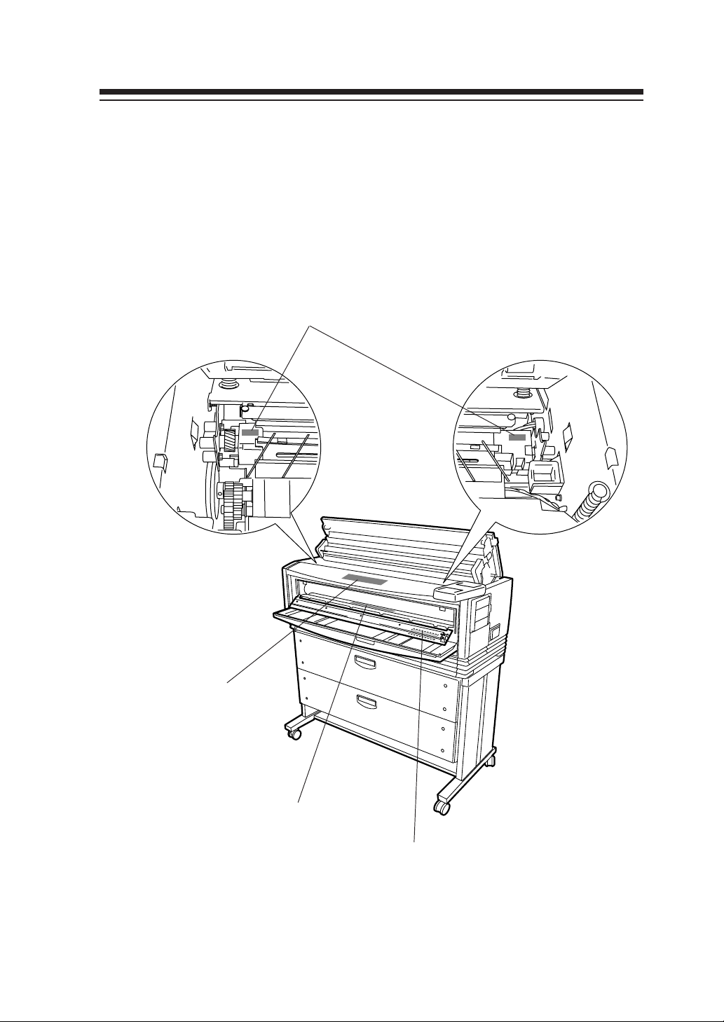
Warning labels
Warning labels are affixed to this device at the locations indicated in the
diagram below. You should understand the meanings of these warning
labels and handling instructions.
3 “WARNING: HIGH VOLTAGE” label
2a “Caution when dealing with
paper jam” label
1 “Caution: high temperature” label
2b “Caution when dealing with
paper jam” label
v
Page 10
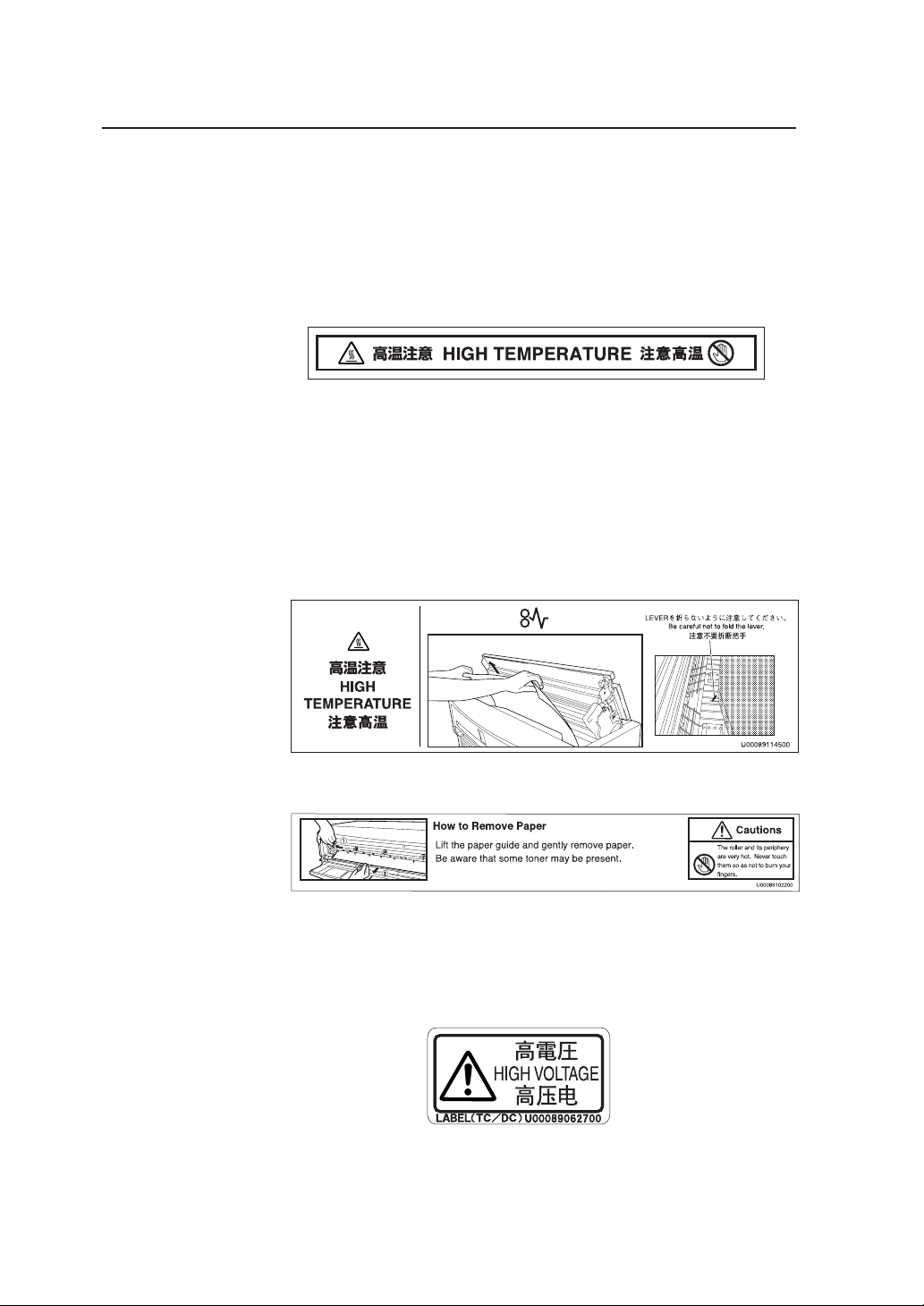
1 “Caution: high temperature” label (It is affixed to the inside of
the fixation door.)
This label cautions you not touch this area due to high temperature.
The fixation device will become hot. Take care to avoid contact when
dealing with paper jams.
2 “Caution when dealing with paper jams” label
This label indicates the direction that jammed paper should be pulled
out when paper is jammed in the fixation device. Follow the
directions on the label to remove the paper.
a
b
3 “WARNING: HIGH VOLTAGE” label
This label cautions against contact due to high voltage application. As
it is dangerous, never contact this area.
vi
Page 11

How to read this manual
Manual make-up
This manual is composed of 13 chapters and an appendix.
Chapter 1 provides information that you should know before using this
device, such as device features and part names. First read chapter 1 for an
understanding of basic matters pertaining to this device.
Chapter 2 provides information on matters you will need to know to
operate this device, such as turning the power on and off, and how to put
paper in the device. Refer to this chapter for basic information on
operating this device.
Chapters 3 to 13 provide information on device functions, operation and
how to manage the settings. First read chapters 3 and 4 for an overview
of functions and operations. Then proceed to the chapter you want to
refer to.
Chapter 5: Refer to this chapter when setting the data format you
will use.
Chapter 6: Refer to this chapter when setting the operating
conditions for the engine of this device.
Chapter 7: Refer to this chapter when you have loaded a different
type of paper in the device and you must change the
settings accordingly.
Chapter 8: Refer to this chapter to confirm Setup contents or to set
the date and time.
Chapter 9: Refer to this chapter when setting the communication
protocol.
Chapter 10: Refer to this chapter when conducting initialization.
Chapter 11, 12: Refer to these chapters when setting the communication
conditions for Ethernet and parallel connection or when
returning to the default settings.
Chapter 13: Refer to this chapter when using "Teioplot".
Chapter 14 provides information on troubleshooting if a problem occurs
with this device. Appropriate countermeasures should be conducted in
accordance with the explanations in this chapter.
The basic specifications and command list for this device can be found in
the appendix. The menu structure is explained in great detail here. Refer
to this menu to perform settings for menus which are not fully explained
by the setting operations for chapters 5 to 13.
vii
Page 12
Notation method
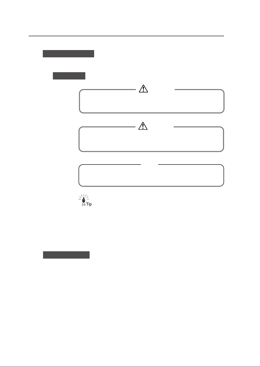
Markings
◆ Contain important information.
Warning
◆ This mark indicates warnings that must be followed
carefully to avoid serious bodily injury or death.
Caution
◆ This mark indicates cautions that must be observed to
avoid damage to the equipment and bodily injury.
Note
This is a “Tip” mark.
Contain additional hints for better use.
DSCAN format
Please remember:
The DSCAN format described in this manual as well as DSCAN that
appears on the operation display are for only customers in Japan.
⇒ This is a “See” mark.
A reference section and page is indicated after this mark.
viii
Page 13
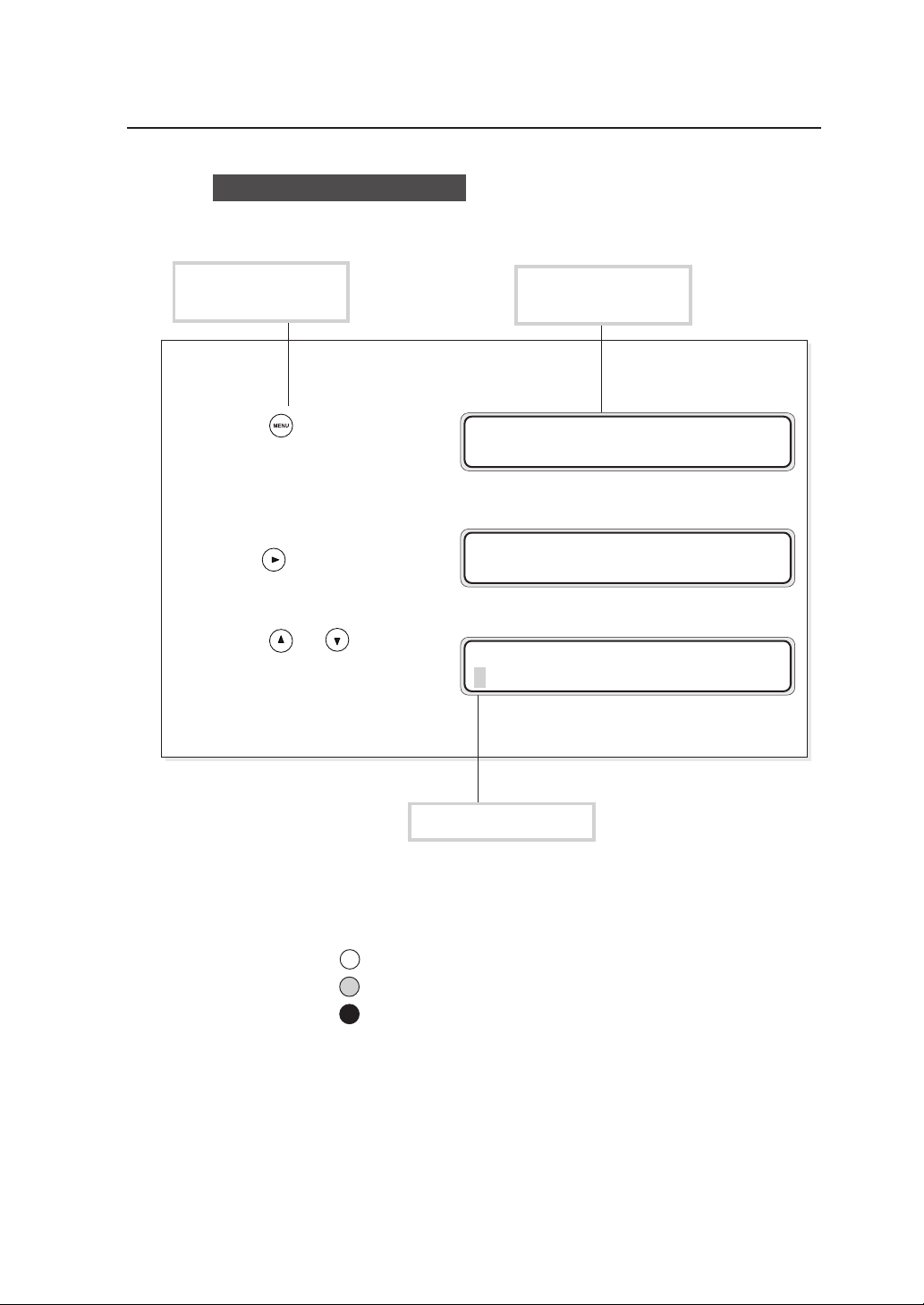
Key/LCD/LED notations
Indicates a control
panel key.
1 Press to proceed to the
menu screen where settings
are managed.
2 Press and select “SETUP.”
3 Press or and select
“PORT2_HPGL.”
Indicates the control
panel LCD.
MENU
#SETUP
SETUP
#PORT1_HPGL
SETUP
#PORT2_HPGL
Indicates flashing light
LED on, flashing, and off states are indicated as follows:
On
Flashing
Off
ix
Page 14
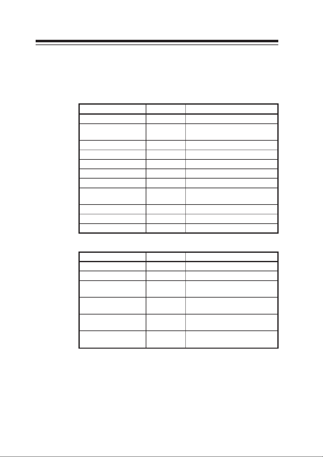
Supplied components
Components and options listed below are included.
If any components are missing or broken, contact your retailer or your
nearest service center.
Item Quantity Remarks
Plotter unit 1 unit
Toner cartridge 3 units
Waste bottle 1 unit Pre-installed
Quick Reference Guide 1 or 2 copies 200V: English and Chinese
CD-ROM 1 set
Paper flange 2 units/drawer
Process cartridge 1 unit With 2 ozone filters
Roll paper 1 box
Scanner exit guide 3 pieces MF model only
Panel sheet 2 sheets 200V only: English and Chinese
Power cable 2 units 200V only: 2 types
For checking at the time of
installation
A0, A1, A3 x 1 unit each, for
checking at the time of installation
Options
Item Quantity Remarks
LP-817 (bucket) 1 unit
LP-819 (carrier sheet set) 1 unit MF model only
LP-840
(color upgrade kit-S)
LP-841
(color upgrade kit-L)
LP-842
(color upgrade kit-S)
LP-843
(color upgrade kit-L)
1 unit
1 unit
1 unit MF-S model (Asia and Oceania)
1 unit MF-L model (Asia and Oceania)
MF-S model
(North/South America and Europe)
MF-L model
(North/South America and Europe)
x
Page 15

TABLE OF CONTENTS
Introduction .......................................................................................... i
Safety Precautions.............................................................................. ii
Warning labels .................................................................................... v
How to read this manual ................................................................... vii
Manual make-up ................................................................... vii
Notation method ...................................................................viii
Markings ............................................................................... viii
DSCAN format ...................................................................... viii
Key/LCD/LED notations ........................................................ ix
Supplied components ......................................................................... x
Chapter 1 Getting started 1-1
Features...........................................................................................1-2
Operating conditions ........................................................................ 1-4
Environmental conditions .................................................... 1-4
Installation space ................................................................. 1-6
Usable paper .......................................................................1-7
Spool memory configuration .............................................. 1-10
The names and functions of each part .......................................... 1-11
Front .................................................................................. 1-11
Right side/rear side ........................................................... 1-12
Interior ............................................................................... 1-13
Control panel .....................................................................1-14
How to read the status displays for this device.............................. 1-17
CONTENTS-1
Page 16

Chapter 2 Basic operations 2-1
Plotting procedures overview...........................................................2-3
Turning the power on and off ........................................................... 2-3
Power on ............................................................................. 2-4
Power off ............................................................................. 2-6
Installation operations ...................................................................... 2-7
Online and offline ........................................................................... 2-10
Online ................................................................................2-10
Offline ................................................................................2-10
Replacing paper rolls ..................................................................... 2-11
Precautions during replacement ........................................ 2-13
How to detach the paper rolls ............................................ 2-14
How to attach the paper roll .............................................. 2-16
Replacing the toner........................................................................ 2-19
Precautions on handling ....................................................2-20
Toner replacement procedures .......................................... 2-21
Replacing the waste toner bottle ................................................... 2-24
Replacing the process cartridge ....................................................2-28
CONTENTS-2
Precautions during replacement ........................................ 2-24
Waste toner bottle replacement procedures......................2-25
Precautions during replacement ........................................ 2-28
Process cartridge replacement procedures ....................... 2-29
Page 17

Manual paper feeding (cut paper).................................................. 2-34
Manual feeding procedures ...............................................2-34
Manual paper feeding procedure ...................................... 2-35
Pause, continue, cancel (and additional printing) ..........................2-39
Print stop ........................................................................... 2-39
Continue printing ............................................................... 2-39
Cancel printing...................................................................2-40
Additional printing ..............................................................2-40
Web function .................................................................................. 2-41
Functions ...........................................................................2-41
Web function startup method.............................................2-42
Cleaning the exterior...................................................................... 2-43
Using paper of new standard series ..............................................2-44
Using paper of Chinese standard series........................................ 2-46
Limiting rolls to be used .................................................................2-48
Chapter 3 Menu overview 3-1
Channels and ports..........................................................................3-3
Data formats ....................................................................................3-3
Data formats which can be used .........................................3-3
Data format auto-judging .....................................................3-3
CONTENTS-3
Page 18

Jobs .................................................................................................3-4
Reprinting ............................................................................3-4
Settings menu .................................................................................. 3-5
PDL menu ........................................................................................3-8
When using our company’s printer driver ............................3-8
Items which you can set .................................................................. 3-9
Idle status ............................................................................3-9
Printing status .................................................................... 3-11
Menu screen .................................................................................. 3-11
Setup menu “SETUP” ........................................................ 3-11
Device menu “DEVICE” ..................................................... 3-12
Paper menu “PAPER” ........................................................ 3-13
Function menu “FUNCTION” ............................................. 3-14
Protocol menu “PROTOCOL” ............................................ 3-15
Reset menu “RESET” ........................................................ 3-16
System menu “SYSTEM” .................................................. 3-17
Chapter 4 Basic Menu Operation 4-1
Summary of basic menu operation .................................................. 4-2
Offline menu operation .................................................................... 4-3
Switching the menu on the same hierarchy ........................ 4-3
Moving the menu hierarchy ................................................. 4-4
Setting or changing the parameters .................................... 4-5
Exiting the setting .............................................................. 4-10
CONTENTS-4
Page 19

Chapter 5 "SETUP" Menu 5-1
Setting parameter items................................................................... 5-2
Setup menu setting parameter table ................................... 5-3
Setup parameter priority mode .......................................... 5-10
PARAMETER MODE (DSCAN only) ................................. 5-11
MEDIA SERIES (HP-GL, TIFF, CALS only) ...................... 5-11
AUTO SUPPLY ................................................................. 5-12
FIXING MODE ................................................................... 5-13
COPY COUNT................................................................... 5-14
SUPPLY PARAM............................................................... 5-15
DRAWING PARAM. .......................................................... 5-17
SCALING PARAM. ............................................................ 5-21
FORMAT PARAM. (HP-GL DSCAN only) ......................... 5-24
PEN PARAMETER (HP-GL DSCAN only) ........................ 5-29
RASTER PARAM .............................................................. 5-34
Chapter 6 "DEVICE" menu 6-1
Setting items .................................................................................... 6-2
POWER SAVE .................................................................... 6-3
EDGE CUT TIMER .............................................................. 6-4
DOOR OPEN CUT .............................................................. 6-5
DENSITY ............................................................................. 6-5
TRACING PAP. MODE ....................................................... 6-5
BOTTLE MODE ................................................................... 6-6
CONTENTS-5
Page 20

Chapter 7 "PAPER" menu 7-1
Setting items .................................................................................... 7-2
MEDIA TYPE ....................................................................... 7-2
MEDIA SERIES ................................................................... 7-3
Chapter 8 "FUNCTION" menu 8-1
Setting items .................................................................................... 8-2
MENU PRINT ...................................................................... 8-3
HPGL SELF PLOT .............................................................. 8-5
DSCAN SELF PLOT ........................................................... 8-6
ERROR LOG ....................................................................... 8-7
JOB LOG ............................................................................. 8-8
ENGINE LOG .................................................................... 8-10
SYSTEM DATE ................................................................. 8-11
SYSTEM TIME .................................................................. 8-11
INIT CHARG. INF .............................................................. 8-11
PRINT CHARG. INF .......................................................... 8-11
MAINTE INFO ................................................................... 8-12
DATA DUMP ..................................................................... 8-12
Chapter 9 "PROTOCOL" menu 9-1
Setting items .................................................................................... 9-2
PDL SELECT....................................................................... 9-3
XPT PORT .......................................................................... 9-4
PRINTER NAME ................................................................. 9-4
USER NAME ....................................................................... 9-5
CONTENTS-6
Page 21

Chapter 10 "RESET" menu 10-1
Reset functions .............................................................................. 10-2
SYSTEM RESET ............................................................... 10-2
PORT RESET ................................................................... 10-3
Chapter 11 "SYSTEM" menu 11-1
Setting items .................................................................................. 11-2
Communication parameter "COMM. PARAM" .................. 11-3
WEB LOCK ....................................................................... 11-5
ENABLE SERIES .............................................................. 11-6
APPLY ROLL .................................................................... 11-8
CHINA SIZE .................................................................... 11-10
INITIAL SET .................................................................... 11-11
LANGUAGE..................................................................... 11-12
LENGTH UNITS .............................................................. 11-12
ADMIN PASSWORD ....................................................... 11-12
Chapter 12 Ethernet parameter "ETHERNET" 12-1
Setting items .................................................................................. 12-2
PORT SELECT ................................................................. 12-4
DHCP ................................................................................ 12-4
IP ADDRESS ..................................................................... 12-5
SUBNET MASK ................................................................. 12-5
ROUTING TABLE.............................................................. 12-6
SETUP DETAILS .............................................................. 12-7
CONTENTS-7
Page 22

Chapter 13 Terioplot 13-1
About Terioplot .............................................................................. 13-2
Terioplot Hardware Requirements ................................................. 13-3
Settings .......................................................................................... 13-4
Restrictions .................................................................................... 13-5
Chapter 14 Troubleshooting 14-1
Troubleshooting ............................................................................. 14-2
When an error message appears .................................................. 14-3
Paper Jam ......................................................................... 14-3
Door Open ....................................................................... 14-14
Operator Call ................................................................... 14-16
Warning ........................................................................... 14-17
Service Call Errors .......................................................... 14-25
Error log ....................................................................................... 14-29
Troubleshooting for ethernet........................................................ 14-34
If "BOTTLE MAINT. STARTS" appears ....................................... 14-36
CONTENTS-8
Classification of Error/Warning ........................................ 14-29
Format of Message ......................................................... 14-29
Log Registration Format .................................................. 14-30
Type of Error Log ............................................................ 14-31
Error Log Classification Table ......................................... 14-33
Page 23

When a print error occurs ............................................................ 14-37
When there is an abnormal sound ............................................... 14-38
Appendix Appendix-1
Basic specifications ............................................................ Appendix-2
Plotter Specification ................................................ Appendix-2
Menu structure .................................................................... Appendix-4
[SETUP] MENU ...................................................... Appendix-4
[DEVICE] MENU .................................................. Appendix-10
[PAPER] MENU .................................................... Appendix-11
[FUNCTION] MENU ............................................. Appendix-12
[PROTOCOL] MENU ............................................ Appendix-13
[RESET] MENU .................................................... Appendix-14
[SYSTEM] MENU ................................................. Appendix-15
Command list .................................................................... Appendix-21
HP-GL,HP-GL/2 Device Control Command List ... Appendix-21
HP-GL,HP-GL/2 Device Plotting Command List .. Appendix-22
HP RTL Plotting Command List ........................... Appendix-25
D-SCAN Format Command List ........................... Appendix-27
TIFF Tag ............................................................... Appendix-33
CALS Format Records ......................................... Appendix-34
ftp Tag .................................................................. Appendix-34
lpd Support Commands ........................................ Appendix-36
xpt(socket I/F) ....................................................... Appendix-36
CONTENTS-9
Page 24

Page 25

Chapter 1
Getting started
Chapter 1 provides necessary information to operate this device. Read
this chapter to understand the basics of this device before proceeding to
the following chapters.
Contents of this chapter
Features
Operating conditions
The names and functions of each part
How to read the status displays for this device
Chapter 1 Before using this device
1-1
Page 26

Features
This device is an electrophotographic black-and-white raster plotter
which produces plots by receiving graphic data created by a work station
or PC (hereafter referred to as a computer.)
This device is equipped with the following features:
High speed plotting
output, high resolution
2-roll paper feeding
mechanism, long drawing
compatible
This device has 80 mm (3.15 inches)/sec recording speed and
can output A0 size drawings at 3.4 sheets per minute. It can also
output high accuracy drawings at 600 dpi resolution.
This device employs a 2-roll paper feeding mechanism that sets
2 sizes from a choice of 4 sizes: A0 size (or 36 inch size), A1 (or
24 inch size), A2 (or 18 inch size), and A3 (or 12 inch size). By
employing paper rolls compatible with drawing sizes ranging
from A0 to A4, a low running cost is achieved by reducing paper
consumption.
This device can also output 2.5 m / 98.4 inch size (10 m / 393.7
inch for the LP-1020L) long sheet drawings. The maximum
plotting range of this device is as follows:
(Note)
Picture quality and printing accuracy can only be assured for plain paper
and recycled paper. (Only up to twice the length of the standard-size
paper can be assured for tracing paper and film.)
LP-1020
• A0 size paper roll : 841 × 2500 mm (33.1 × 98.4 inches)
• A1 size paper roll : 594 × 1830 mm (23.4 × 72 inches)
• A2 size paper roll : 420 × 1200 mm (16.5 × 47.2 inches)
• A3 size paper roll : 297 × 920 mm (11.7 × 36.2 inches)
LP-1020L
• A0 size paper roll : 841 × 10,000 mm (33.1 × 393.7 inches)
• A1 size paper roll : 594 × 10,000 mm (23.4 × 393.7 inches)
• A2 size paper roll : 420 × 1220 mm (16.5 × 47.2 inches)
• A3 size paper roll : 297 × 920 mm (11.7 × 36.2 inches)
1-2
Page 27

▼Features
Manual feeding
mechanism
Multiport interface
Supports a variety of
paper types
Front paper feeding/
finished drawing outlet
This device is equipped with a manual feeding print function.
(Note)
The picture quality and printing accuracy for manually fed printing cannot
be assured.
The device is equipped with an Ethernet interface and allows for
network connection to network. It can also be equipped with
both parallel interface and USB interface. In addition, 10 logical
ports can be used for the Ethernet interface, which then allows
up to 12 computers, including parallel interface and USB
interface, to be simultaneously connected.
4 types of rolls—paper, recycled paper, tracing paper, and
film—are supported.
The device has a front paper feeding and finished drawing outlet
structure. This allows for paper to be loaded and output drawings
to be processed only at the front of the device. This means that
the device requires only a small installation space.
The device was designed for simple, front operation, allowing
paper to be loaded and toner cartridges to be replaced with ease.
Chapter 1 Before using this device
1-3
Page 28
Operating conditions
This section covers operating conditions of this device including
environmental conditions, installation space, supported papers and spool
memory configuration.
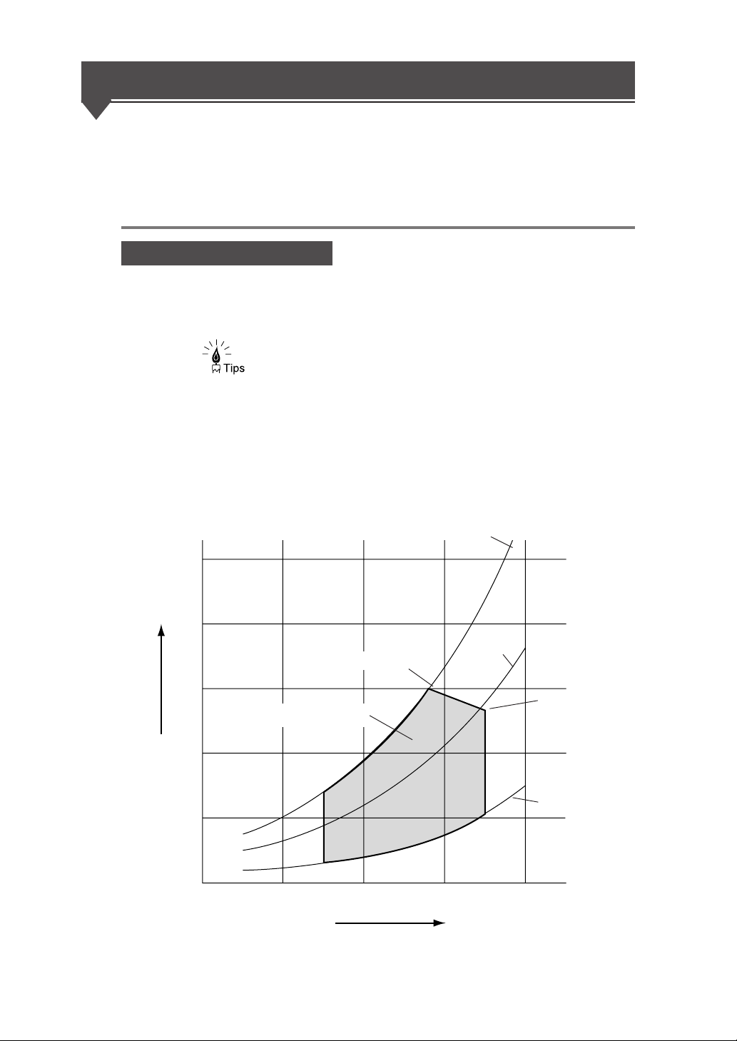
Environmental conditions
This device should be used within the temperature and humidity ranges
indicated in the graph below.
◆ To obtain the best picture quality, use the device within a
temperature and humidity range of 20 to 30°C, 45 to 60%RH.
(relative humidity)
■Operating temperature and humidity range
Vapor
pressure
(×103Pa)
80%RH
5
4
28°C, 80%RH
3
Operating temperature and
humidity range
2
1
15°C
0
10
20 30
Temperature
(50%RH)
35°C
35°C, 48%RH
20%RH
(°C)
40
1-4
Page 29

▼Operating conditions
Do not install the plotter in the following places:
◆ Places exposed to direct sunlight
◆ Places subject to vibration
◆ Places with excessive dust
◆ Places subject to extreme changes in temperature or humidity
◆ Places near an air conditioner or a heater
◆ Places where the plotter may get wet
◆ Places subject to direct air flow from a vent
◆ Places near a diazo copier that may generate ammonia gas
◆ Places with poor ventilation
Chapter 1 Before using this device
1-5
Page 30
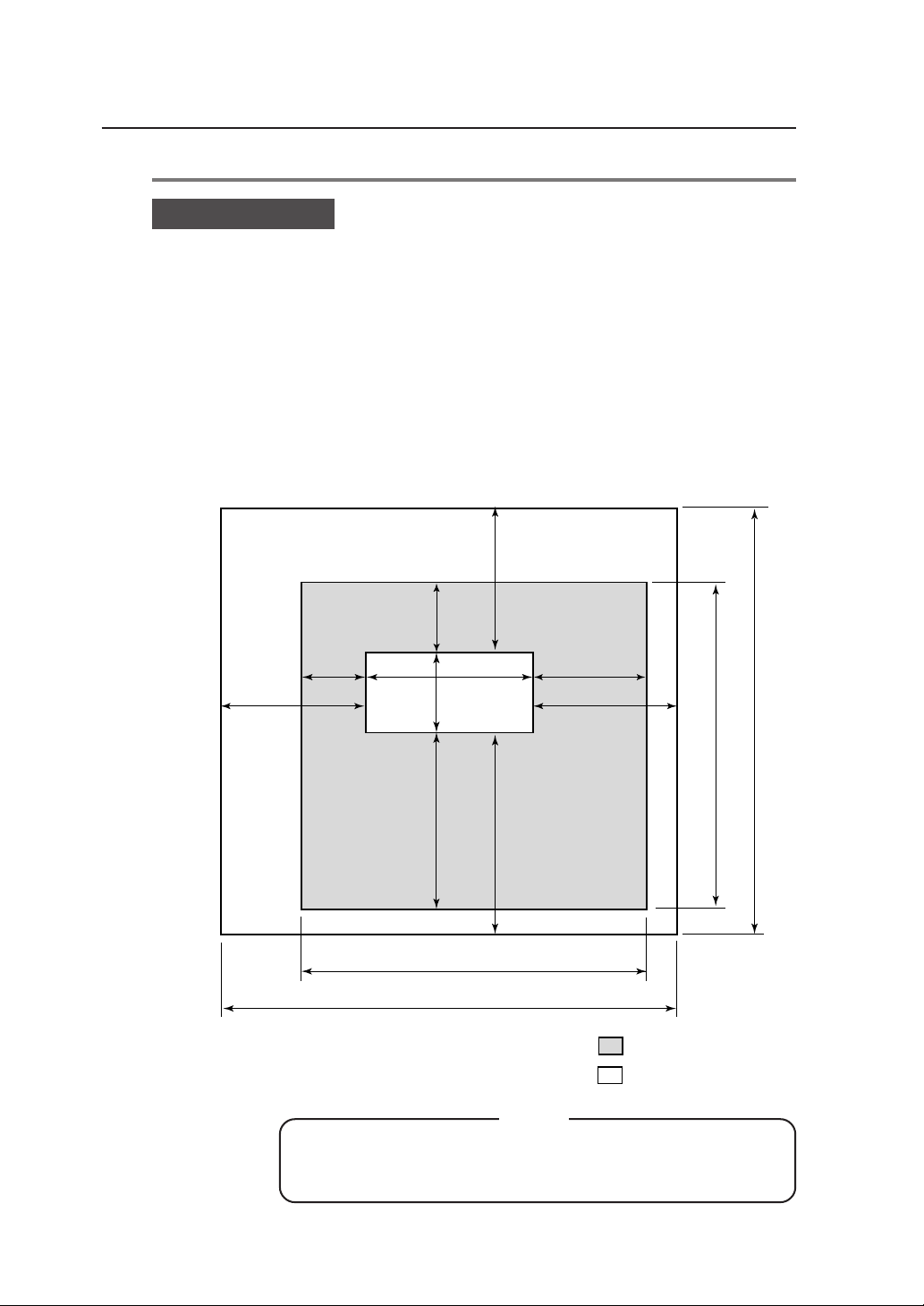
Installation space
When installing this device, space to the front, rear, left and right sides of
the device should be accommodated for the replacement of consumables,
the processing of output drawings, and the ventilation. The minimum
installation space indicated in the diagram below should be ensured. The
maintenance space indicated in the diagram below is needed to perform
parts replacement, etc.
■Installation/maintenance space
300
700
(27.6)
(11.8)
300
552
(11.8)
1154
(45.4)
(21.7)
600
(23.6)
600 (23.6)
700 (27.6)
1-6
(Height is 2000 mm / 78.7 inches)
◆When moving this device from its current location to a
different location, contact our company’s service center.
800 (31.5)
2554 (100.6)
900 (35.5)
2054 (80.9)
Note
1652 (65)
2052 (80.8)
Installation space
Maintenance space
units: mm (inch)
Page 31

Supported
▼Operating conditions
Use roll paper specified by our company as indicated below:
Note
◆If paper not specified by our company is used, picture quality
cannot be assured. Moreover, the device may malfunction.
■Roll paper specified by our company
Part No. Paper type & size
LP-733
LP-780 A1 size width (594 mm / 23.4 inches)
LP-788 A2 size width (420 mm / 16.5 inches)
Plain paper
(67g / m
LP-781 A3 size width (297 mm / 11.7 inches)
LP-735
LP-782 A1 size width (594 mm / 23.4 inches)
LP-740 A2 size width (420 mm / 16.5 inches)
Tracing paper
(75g/m
2
LP-783 A3 size width (297 mm / 11.7 inches)
LP-744
LP-786 A1 size width (594 mm / 23.4 inches)
LP-743 A2 size width (420 mm / 16.5 inches)
Mat film
(#300)
LP-787 A3 size width (297 mm / 11.7 inches)
LP-734
LP-947 A1 size width (594 mm / 23.4 inches)
LP-948 A2 size width (420 mm / 16.5 inches)
Recycled paper
(66g / m
LP-949 A3 size width (297 mm / 11.7 inches)
Chapter 1 Before using this device
A0 size width (841 mm / 33.1 inches)
2
)
A0 size width (841 mm / 33.1 inches)
)
A0 size width (841 mm / 33.1 inches)
A0 size width (841 mm / 33.1 inches)
2
)
1-7
Page 32

■9×12 inch series
The following roll paper of the widths can be also used.
Roll width Name of fixed form Lengthwise Widthwise
36 inches
(914.4 mm)
24 inches
(609.6 mm)
18 inches
(457.2 mm)
12 inches
(304.8 mm)
E-form size
D-form size
D-form size
C-form size
C-form size
B-form size
B-form size
A-form size
1219.2 mm
(48 inches)
914.4 mm
(36 inches)
914.4 mm
(36 inches)
609.6 mm
(24 inches)
609.6 mm
(24 inches)
457.2 mm
(18 inches)
457.2 mm
(18 inches)
304.8 mm
(12 inches)
914.4 mm
(36 inches)
609.6 mm
(24 inches)
609.6 mm
(24 inches)
457.2 mm
(18 inches)
457.2 mm
(18 inches)
304.8 mm
(12 inches)
304.8 mm
(12 inches)
228.6 mm
(9 inches)
■8.5×11 inch series
Roll width Name of fixed form Lengthwise Widthwise
34 inches
(863.6 mm)
22 inches
(558.8 mm)
17 inches
(431.8 mm)
11 inches
(279.4 mm)
1-8
E-form size
D-form size
D-form size
C-form size
C-form size
B-form size
B-form size
A-form size
1117.6 mm
(44 inches)
863.6 mm
(34 inches)
863.6 mm
(34 inches)
558.8 mm
(22 inches)
558.8 mm
(22 inches)
431.8 mm
(17 inches)
431.8 mm
(17 inches)
279.4 mm
(11 inches)
863.6 mm
(34 inches)
558.8 mm
(22 inches)
558.8 mm
(22 inches)
431.8 mm
(17 inches)
431.8 mm
(17 inches)
279.4 mm
(11 inches)
279.4 mm
(11 inches)
215.9 mm
(8.5 inches)
Page 33

■30×42 inch series
Roll width Name of fixed form Lengthwise Widthwise
(762.0 mm)
■Map series
Roll width Name of fixed form Lengthwise Widthwise
700.0 mm
(27.6 inches)
500.0 mm
(19.7 inches)
■DIN series
Roll width Name of fixed form Lengthwise Widthwise
707.0 mm
(27.8 inches)
500.0 mm
(19.7 inches)
30 inches
30× 42 size form size
B1 form size
B2 form size
B2 form size
B1 form size
B2 form size
B2 form size
B3 form size
1066.8 mm
(42 inches)
1000.0 mm
(39.4 inches)
700.0 mm
(27.6 inches)
700.0 mm
(27.6 inches)
1000.0 mm
(39.4 inches)
707.0 mm
(27.8 inches)
707.0 mm
(27.8 inches)
500.0 mm
(19.7 inches)
▼Operating conditions
762.0 mm
(30 inches)
700.0 mm
(27.6 inches)
500.0 mm
(19.7 inches)
500.0 mm
(19.7 inches)
707.0 mm
(27.8 inches)
500.0 mm
(19.7 inches)
500.0 mm
(19.7 inches)
353.0 mm
(13.9 inches)
Chapter 1 Before using this device
■China series
The China series roll cannot be used for plotting with cut sheet feeding. It
can be used for real size plotting only.
Chinese series
A0 roll width
914 mm
(36 inches)
910 mm
(35.8 inches)
900 mm
(35.4 inches)
880 mm
(34.6 inches)
Chinese series
A1 roll width
620 mm
(24.4 inches)
610 mm
(24 inches)
---
---
Chinese series
A2 roll width
450 mm
(17.7 inches)
440 mm
(17.3 inches)
Chinese series
A3 roll width
310 mm
(12.2 inches)
297 mm
(11.7 inches)
1-9
Page 34

Paper storing precautions are as follows:
◆Store the paper in a cool dark place with in the specified
humidity ranges.
◆Store the paper in it’s packaging material so that dust will not
accumulate on the paper.
Spool memory configuration
Spool memory configurations are available for this device as specified
below.
Notes
Expansion kit
LP-815
Extends spool memory.
Spool memory is the memory needed to receive plotting data.
If plots cannot be produced normally due to spool memory
shortage, installing the following options allows plots to be
produced normally.
■Spool memory configuration when LP-815 is installed
Note
◆The maximum capacity to be actually spooled is slightly
different from the values indicated in the above table.
Confirm the capacity by executing “MENU PRINT.”
1-10
Page 35

The names and functions of each part
This section explains the names, usage information, and functions of each
part of this device.
Front
Chapter 1 Before using this device
1 Roll 1 drawer (door 1) Install paper roll. (⇒ page 2-11)
2 Roll 2 drawer (door 2) Install paper roll. (⇒ page 2-11)
3 Manual feed drawer (door 4)
Open this drawer when a paper jam occurs during
manual feeding. (⇒ page 14-3)
4 Finished drawing outlet Drawings exit from here.
5 Top cover (door 6) Open this cover when a paper jam occurs near the top door.
(⇒ page 14-3)
6 Fixation door (door 7) Open this door when a paper jam occurs in the vicinity of the finished
drawing outlet. (⇒ page 14-3)
7 Manual paper feeding guide (door 8)
Open this door when feeding the paper manually. (⇒ page 2-34)
8 Manual feed inlet Insert paper from this inlet during manual feeding. (⇒ page 2-34)
9 Toner cover Open this cover when replacing toner. (⇒ page 2-19)
0 Control panel The LEDs and LCD which indicate device status and the keys to set
various functions are laid out here. (⇒ page 1-14)
A Waste toner door Open this door to replace a waste toner bottle. (⇒ page 2-24)
1-11
Page 36

Right side/rear side
1 Main power switch Turns the device power on and off. (⇒ page 2-3)
2 Power cord Plug this cord into a power cord socket.
3 Parallel interface connector
This is an interface connector conforming to the standards of the
Parallel interface connector of Centronix.
4 Ethernet interface connector
This is an interface connector for a 100 BASE-TX and 10 BASE-T
Ethernet interface connector.
5
USB interface connector
6 Cutter door (door 5) Open this door to deal with paper jams at the cutter area.
7 Cutter door inside (door 9)
8 Cutter door lower small door (door 10)
This is an interface connector for a USB 2.0 interface connector.
(⇒ page 14-3)
Open this door to deal with paper jams at the cutter area.
(⇒ page 14-3)
Open this door to deal with paper jams at the cutter area.
1-12
Page 37

Interior
▼The names and functions of each part
Chapter 1 Before using this device
1 Paper feed knob Feeds the end of the roll to the paper feed inlet. (⇒ page 2-11)
2 Paper flange This flange is attached to the roll paper. (⇒ page 2-11)
1-13
Page 38

Control panel
1 LEDs
The device status is
indicated by LED’s on,
flashing, and off.
The keys, LEDs and LCD are laid out on the control panel as illustrated in
the following diagram.
2 LCD
The status of this device, as well as a
menu to set the device functions appears
on a 20-digit, 2-line display.
4 Power key
Use this key to turn
ON/OFF this device.
1-14
3 Keys
Use these keys to set device functions.
Page 39

▼The names and functions of each part
LCD, LEDs, and key functions
Number Name Function
Error lamp (red)
Toner lamp (green)
Waste toner lamp
LED’s
Display LCD
(green)
Process lamp
(green)
Menu lamp
(green)
MENU key
Indicates the presence or absence of errors.
On: Error present
Off: No error present
Indicates the amount of remaining toner.
On: There is sufficient toner.
Flashing: Toner is running low.
Off: There is no toner (plots cannot be produced
without replenishment.)
Indicates the toner waste bottle replacement time.
On: Normal
Flashing: Replacement timing is approaching
Off: Plots cannot be produced without replacement
Indicates the process cartridge replacement time.
On: Normal
Flashing: Replacement time is approaching
Off: Process cartridge is not installed.
Indicates that this device is ready for setting,
receiving data, or printing.
On: Setting operations can be performed
Off: Ready to receive data and print.
Displays a variety of messages in a 20-figure and 2line display to inform you of the device status.
Switches the status of the device from setting ready
status to data receive and print ready status.
Chapter 1 Before using this device
Keys
Power
ENTER key
CANCEL key
Key
Key
Key
Key
Power key
Inputs the parameters.
Cancels parameter input.
Switches menu items and changes parameters.
Switches menu items and changes parameters.
Switches menu items/hierarchy and changes.
Switches menu items/hierarchy and changes.
Turns the device power on and off.
1-15
Page 40

How to read the status displays for this device
This section explains the control panel LEDs and LCD which inform you
of the status of the device.
The following are the main displays.
Data standby display
Standard configuration
PR I NT READY
This is a print ready status.
Data processing display
PROCESS I NG ✽ S001
F01 HPGL J009
Communication channel name
F : FTP protocol
L : LPD protocol
X : XPT protocol
PR : Parallel
USB : USB
Error lamp
Menu lamp
Indicates that data is being processed.
(flashing)
Sxxx: The job number standing
by for processing
PDL name
HPGL
DSCAN
TIFF
CALS
Port number (this number is not displayed when using
parallel or USB interface.)
Jxxx: The job number being processed
Error lamp
Menu lamp
1-16
Data is being processed.
The various information for the data currently being processed is displayed.
Note
◆Parallel and USB are only displayed when each interface is
installed.
Page 41

Printing in progress display
▼How to read the status displays for this device
PR I NT 0 2 / 9 9✽ S001
F01 HPGL J009
Data is being printed.
The various information for the data currently being printed is displayed.
Print information display
T O T A L CO U N T mmmmmm
T O T A L RUN ( m ) mmmmmm
This display appears when is pressed in data standby or print ready status.
The total number of prints and the length of media printed appear.
Error lamp
Menu lamp
Scheduled number of prints
Number of prints executed
Error lamp
Menu lamp
◆ Many of our customers who have signed a maintenance
agreement regularly telephone our service center for
assistance. When contacting our service center, please make
a note of this information for your reference.
◆ This display appears for approximately three seconds, after
which the display will automatically return to the original data
standby display condition.
Chapter 1 Before using this device
Setting ready display
MENU
#SETUP
The functions for this device can be set. ⇒ chapter 3
Error display
CLOSE DOOR1
An error has occurred.
Errors are classified according to those which can be dealt with by the operator, or
errors which can only be dealt with by your dealer or our service center, etc. ⇒
Chapter 14
Error lamp
Menu lamp
Error lamp
Menu lamp
1-17
Page 42

Warming up display
WA RM I NG U P n n n
Displays the warming-up status and the time remaining until the device is ready.
Power saving display
POWER SA V I NG
This display appears when the device enters the power saving mode after the data
standby status has continued for a certain period of time.
Error lamp
Menu lamp
Counts down
1-18
Page 43

Chapter 2
Basic operations
Chapter 2 describes basic operating procedures for this device such as
turning the power on and off, replacing paper, and replacing toner will be
explained.
Contents of this chapter
Plotting procedures overview
Turning the power on and off
Installation operations
Online and offline
Replacing paper rolls
Replacing the toner
Replacing the waste toner bottle
Replacing the process cartridge
Manual paper feeding (cut paper)
Pause, continue, cancel, and additional printing
Web function
Cleaning the exterior
Using paper of new standard series
Using paper of Chinese standard series
Limiting rolls to be used
Chapter 2 Basic operations
2-1
Page 44

Plotting procedures overview
Plotting is usually conducted in accordance with the following
procedures.
For information on computer operations, refer to your computer manual.
1 Turn on the power for the computer and this device.
For information on turning on the device power, refer to “Turning the
power on/off” (⇒ page 2-3)
2 Confirm the status of the device on the control panel.
Confirm that the LEDs are not indicating abnormalities and that the LCD
indicates Data standby status.
Press when the Menu lamp is on.
When the Toner lamp is flashing or off, replace the toner. (⇒ page 2-19)
When the Toner waste bottle lamp is flashing or off, replace the waste
bottle. (⇒ page 2-24)
When the Process lamp is flashing or on, replace the process cartridge.
(⇒ page 2-28)
When the Error lamp is on, refer to chapter 14 for information on
troubleshooting.
3 Open your application software on your computer and
create a drawing.
If the device settings do not conform to the application software you are
using, reset the settings for this device (⇒ Chapters 5 to 12).
4 Send the data from the computer to this device.
2-2
Page 45

Turning the power on and off
This device has two power switches: the main power switch located at
the lower-left as seen from the rear of the device; and the power key on
the control panel.
The device power is turned on by first turning on the main power switch, and
then pressing the device’s control panel power key.
Notes
◆While data is being processed, do not turn off the main
power switch. Doing so may damage the system.
◆When the power is on and the Main power switch is turned
off, or when the power goes out due to blackout etc.,
restoring the power (turning the Main power switch back on
or resetting from a blackout) is the first step, but will not turn
the plotter on. You must also turn ON the power key on the
control panel.
Chapter 2 Basic operations
Main power switch
Control panel
Power key
2-3
Page 46

Power on
1 Turn on the Main power switch located at the lower-left
2 Press the power key located on the control panel of this
as seen from the rear of the device.
Main power switch
Press the power switch toward the ⎪
symbol (upwards).
2-4
device (when the main power switch is on).
INITIAL IZING
WA I T A MOME N T
When you first turn on the power after purchasing this device, a guidance
display prompts you to set the panel's display language. If this setting has
already been completed, this message is omitted.
LANGUAGE?
✽ ENGL I SH
Page 47

▼Turning the power on and off
When a job is saved, the following message appears and the device stands
by for selection.
When a job is not saved, this message is omitted.
DELETE JOB?
Y=ENTER N=CANCEL
If a key input is not made,
this message will time-out
after about 10 seconds
and the device starts up
with the job in saved
condition.
Under normal conditions, the display reads “INITIALIZING STANDBY”
and is changed to the following message.
SYSTEM VERS I ON
01A
The message is changed to the “WARMING UP".
WARM I NG U P n n n
Warm up will take about 4
minutes. (about 8 minutes
with LP-1020L)
nnn: a count down for the
warm up is displayed.
The message indicates that the device is now online (“PRINT READY”).
Chapter 2 Basic operations
PRINT READY
A “PRINT READY” message indicates that the device is functioning
normally.
2-5
Page 48

Power off
1 Press the Power key on the device panel for about 1
When turning the power off, confirm that the device is in the data receive
standby mode.
second.
Release the key when the display reads "SHUTTING
DOWN."
When a job is present, it is automatically saved and will be printable the
next time you turn the power on.
(Only when HDD is installed)
Note:
Even when “SHUTTING DOWN” appears, the
power will not turn off until you release the
power key.
2-6
SHUTDOWN
WA I T A MOME N T
When the shut down process has been completed, the power will turn off.
This indicates that the
device is executing a shut
down.
2 Turn the main power off when you are not using this
device for an extended period of time.
Main power switch
Press the power switch toward the symbol
(downwards).
Page 49

Installation operations
When you first turn on the power after purchasing this device, it will start
up differently from how it will regularly start up thereafter. A guidance
display will prompt panel display language selection, initializing of
parameters appropriate for your region, and the setting of an IP address.
By setting this IP address when the plotter is installed, you will be able to
utilize the browser of a host computer on the same network as the plotter
to make various settings.
Moreover, when using the network to operate the device, you must also
initialize the following plotter settings from the browser or the device
panel. If you neglect to set these settings, connection with the router will
not be possible.
1 Subnet mask settings
2 Routing table settings
Once you set the panel display language selection, initialized optimal
setup parameters according to your region, and set IP address settings,
this guidance display will not appear the next time the power is turned on.
When “INITIALIZE” is executed in the System menu (explained later),
the IP address will return to an unset condition, and the IP address setting
guidance display will appear once again when the power is turned on.
Notes
◆The panel display language selection allows you to select
the language which will appear on the device control panel,
and can also be set from “LANGUAGE” in the System menu.
◆Initializing of the optimal parameters for your region for such
items as media series can also be set from “INITIALIZE” in
the System menu.
◆The IP address is a communication parameter during
Ethernet connection which is assigned specifically to each
device.
Chapter 2 Basic operations
2-7
Page 50

■Turning on the power
INITIAL IZING
WA I T A MOME N T
LANGUAGE?
✽ ENGL I SH
Select the language to be displayed on the panel using the
, keys.
LANGUAGE?
✽ ENGL I SH
Press the key to go to the confirmation screen.
LANGUAGE?
✽ ENGL I SH OK?
Press the
key to choose this setting.
INITIAL SET
✽ STANDARD
Select the optimal setup parameters according to your region
using the
, keys.
When a language has already been selected.
2-8
INITIAL SET
✽ CH I NA
Press the
key to go to the confirmation screen.
INITIAL SET
✽ CH I NA OK?
Press the
Proceed to the next page
key to determine this setting.
Page 51

Continued from the preceding page
US I NG NETWORK?
Y=ENTER N=CANCEL
Press the key.
▼Installation operations
IP ADDRESS?
✽ 000. 000 . 000 . 000
Input the values using the , , , ,
keys.
IP ADDRESS?
✽ 192.168.123.123
Press the
screen.
key to go to the confirmation
IP ADDRESS?
✽ 192.168.123.123 OK?
Press the key to determine the selection.
The device will be automatically
rebooted.
DISPLAYING NEXT?
Y= ENTER N=CANCEL
Chapter 2 Basic operations
SYSTEM VERS I ON
01A
PR I NT READY
2-9
Page 52

Online and offline
The device is “ONLINE” when it can receive and print data from the host
computer and is “OFFLINE” when settings are being input on the control
panel. You must set the device to “offline” to operate the menu from the
control panel.
Online
To print from the host computer, the device must be online. Always make
sure that the device is online to print from the host computer. If the device
is not online, follow the procedures below to set the device online. The
device will automatically go online when the device power is turned on.
1 Press the key to turn the Menu lamp off.
Offline
PR I NT READY
To select menu operations and paper feed method etc. using the device
control panel, the device must be offline. Before using the control panel
keys, set the device offline according to the following procedures.
1 Press the key to turn the Menu lamp on.
MENU
#SETUP
2-10
Page 53

Replacing paper rolls
How to detach and reattach the paper rolls will be explained here.
Detach and replace a paper roll when the device has run out of paper or
when you change the paper roll size on type. When the paper is used up
during printing, the Error lamp will turn on and the LCD will display the
following message:
Example: The screen requesting the A3 tracing paper to be loaded in the
roll 1 drawer.
SET PAPER
A0
or
SET PAPER
ROL L 1 A 0
or
SET PAPER
A0 ( TRACE )
Chapter 2 Basic operations
or
SET PAPER
ROL L 1 A 0 ( TRACE )
◆ When a paper replacement message appears on the LCD, it is
possible to cancel the drawing that you sent to print. Use this
function when you don’t have the required paper.
Example)
SET PAPER
A1
Press the key.
CANCEL PR I NT ?
Press the
*Printing will be cancelled.
key.
PR I NT READY
2-11
Page 54

If an error message about paper supply appears on LCD, paper of larger
size than required (or, if a type of paper is specified, paper of different
type) can be chosen for printing.
e.g.
SET PAPER
A1
Press the key.
FORCE PR I NT?
Press the
key.
PR I NT 0 1 / 0 1✽ S001
F01 HPGL J009
*Prints only when paper of larger size than required is available or if
paper of a different type is available.
*Alternative print is disabled, if printing on the manually fed paper.
Notes
◆"A1" in the above example indicates the paper roll width and
its indication changes as follows:
Example:
A series: "A0", "A1", "A2", "A3"
9" series: "36"", "24"", "18"", "12""
8.5" series: "34"", "22"", "17"", "11""
30x42 series: "30""
MAP series: "707 mm", "500 mm"
DIN series: "707 mm", "500 mm"
Chinese series: "914 mm", "620 mm", "450 mm"
"310 mm","297 mm"
◆When a paper type is specified as "SET PAPER A0
(TRACE)" and the paper roll is loaded, the display may be
automatically switched to the paper menu. In such a case,
set the type of the paper roll.
◆If the media series is different (that is, appropriate media series
was not loaded into the tray), the display may be automatically
switched to the paper menu when the paper roll is reloaded. In
such a case, set the media series of the paper roll.
2-12
Page 55

Precautions during replacement
◆The rolls are heavy so be careful not to hurt yourself by
dropping them while you are replacing the rolls.
◆When attaching the rolls, use a cutter to cut the end of the
paper roll. While doing this, take care not to cut yourself or
damage the device.
◆When opening and closing the paper roll drawers, take care
not to get your hands caught in the drawer.
Do not open other paper roll drawers while one paper roll
drawer is open. Doing so will increase your chances of
getting your hands caught in the drawers.
▼Replacing paper rolls
Caution
Chapter 2 Basic operations
Notes
◆If you change the paper type, you must also change the
device settings accordingly. ⇒ chapter 7
◆Use media types specified by our company.
If you use media types which are not specified by our
company, we cannot assure printing quality.
◆Store the paper in a cool, dark location with low humidity.
2-13
Page 56

How to detach the paper rolls
1 Pull out the Roll 1 or Roll 2 drawer.
Use your fingers to grasp the handle in the
center of the drawer and pull the drawer out
gently.
(The diagram indicates a case where the Roll 2
drawer is opened.)
2-14
2 Rewind the paper roll and then remove it.
Turn the paper flange in the direction indicated
in the diagram and continue to rewind the roll
until you see the end of roll. Lift up the paper
flange and remove the paper roll.
Paper flange
Page 57

▼Replacing paper rolls
3 Remove the paper flange and take out the paper roll.
Loosen the paper flange by turning the knobs in
the “OPEN” direction and remove both ends of
the paper flange.
L
O
C
S
E
O
P
N
E
Note
Knob
◆Take care not to use excessive force
when you turn the paper flange knobs.
The flange ends may come off.
Chapter 2 Basic operations
2-15
Page 58

How to attach the paper roll
◆ The paper flange ends do not have a designated right or left
side. You can attach them to either side.
1 Attach the paper flange to a paper roll.
L
O
C
S
E
O
P
N
E
Knob
2 Move the flange guide.
Push in the paper flange ends until they contact the
paper roll tube, then secure the flange ends by
turning the knob in the “CLOSE” direction.
Note
◆If the paper flange knobs are loosely
fitted, the paper roll will move adversely
to the right and left and negatively affect
the drawing. Make sure that the knobs
are tightened securely.
Label
the label which is affixed to the inside of the drawer
indicates the flange positions for the application of
different roll widths. Move the flange guide to
match the paper roll size you are using.
C
N
Flange guide
3 Load the paper roll into the drawer.
Hold the paper roll so that the end of the paper is
positioned at the bottom facing the back of the
device. Then align the paper flange to the
depressions in the flange guide and gently insert the
flange in place.
◆Take care not to drop the paper roll
while performing these activities.
L
O
S
E
O
P
E
Note
2-16
Page 59

▼Replacing paper rolls
4 Insert the end of the paper roll into the paper feed inlet of
the device.
Turn the paper flange and insert the end of the
paper roll so that it is straight. Turn the paper
feed knob so that the end of the paper roll
projects about 10 cm.
Paper feed knob
5 Cut the end of the paper.
While holding the end of the paper roll, cut it off
with the cutter.
Chapter 2 Basic operations
The “Paper cutter position” label is affixed to
both ends of the space where the cutter blade
should be inserted. Insert the cutter blade into
the space where the label arrow is pointing.
Slide the cutter blade along the space and cut the
paper.
◆ The paper can be cut cleanly when the
cutter is inserted in a perfectly sideways
direction.
Caution
◆Take care not to hurt yourself and damage the device when
handling the cutter.
◆Handle the cutter blade with care so that you do not break it.
◆When sliding the cutter along the space, take care not to cut
the back of your hand on the sides of the paper tray.
2-17
Page 60

6 Close the paper roll drawer.
Gently push in the Roll 1 or Roll 2 drawer.
When the paper roll drawer is closed, the following
message appears.
WA I T A MOME N T
(It will take about 30 seconds until paper feeding is ready.)
◆After closing the paper roll drawer, wait until the “WAIT A
MOMENT” message disappears before opening the paper
roll drawer again. As the device initiates a paper detection
just after the paper roll drawer is closed, so opening the
paper roll drawer during this operation may cause a paper
jam.
After the replacement, the device will return to the
status before the paper roll was replaced.
Note
2-18
Note
◆If you change the type of paper roll, you must change the
corresponding settings, referring to “Paper settings” (⇒
page 7-2).
Page 61

Replacing the toner
When the toner level runs low, the Toner lamp will flash. Although plots
can still be produced under this condition, obtain a new toner cartridge as
soon as possible and replace the toner.
When there is no more toner availabe, the Toner lamp will go out, the
Error lamp will come on, and printing will no longer be possible. The
following message appears on the LCD.
SET TONER CARTR I DGE
OPEN LEVER
If the Toner lamp starts flashing or the ERROR message appears, replace
the toner according to the procedures indicated below.
◆ When you open the toner door, you will find a “Toner
replacement” label affixed to the inside surface. Refer to this
when replacing toner.
◆ After the Toner lamp starts flashing, approximately 50 m of
plots can be produce at normal size and density.
Chapter 2 Basic operations
Note
◆If plots with a high printing rate—such as drawings
containing many solid print areas and inversed (black and
white inverted) drawings—are printed just before the toner
runs out, the toner may be used up and the device may be
damaged.
To avoid such a case, refill toner as soon as possible when
the toner lamp is flashing.
2-19
Page 62

Precautions on handling
Do not throw empty toner cartridges into fire. Doing so
may cause accident and fire.
Put the waste cartridge into the wrapping contained in the
toner cartridge package and dispose of it as non-burnable
garbage.
◆Do not drop and tap the toner cartridge with force. Doing so
may cause the toner to leak from the cartridge.
◆Do not directly touch the toner. If the toner gets on your skin
or clothing, quickly wash it off with water.
◆Take care not to get toner in your eyes or breathe it in. If the
toner gets in your eyes, wash your eyes out with lots of water
and consult your physician.
Warning
Caution
2-20
Notes
◆If you move the toner cartridge from a cold to a warm
location, leave it in room temperature for over three hours
before using it.
◆After replacing the toner, try to use it up within a six month
period. A toner cartridge installed for an extended period of
time will degrade the drawing quality.
◆Keep toner cartridges in a cool, dark place.
◆Use only genuine toner cartridges.
Page 63

Toner replacement procedures
◆Toner should be replaced only when the device power is On.
If the toner is replaced while the power is Off, the device will
not be able to detect the amount of toner and an error status
will not be cancelled even when toner has been replaced
correctly.
◆Replace toner after plotting finishes. Replacing the toner
during plotting may cause the operation to stop and the
plotting data to be lost.
1 Open the toner cover.
▼Replacing the toner
Notes
Chapter 2 Basic operations
2 Take out the new toner cartridge from the package.
3 Mix the toner by shaking the new toner cartridge.
Shake it strongly up, down, left and right, five or
six times.
2-21
Page 64

4 Set the toner cartridge into the main unit.
5 Pull the lever to the right end.
2-22
At this time, the following message appears on
the LCD. After performing the procedure 6
operation, return the lever and remove the toner
cartridge.
CLOSE LEVER
REMOVE CARTR I DGE
If the above message does not appear, check to
see that the lever has been pulled up to the right
end.
Page 65

▼Replacing the toner
6 Tap the cartridge to allow toner to drop down.
7 Return the lever to the left.
Chapter 2 Basic operations
8 Remove the toner cartridge and close the cover.
At this time, the following message appears on
the LCD.
WA I T A MOME N T
2-23
Page 66

Replacing the waste toner bottle
When the waste bottle is nearly full with waste toner, the Waste toner
lamp will flash. Although plots can continue to be produced for a little
while longer, replace the waste bottle soon.
When the waste bottle becomes full with waste toner, the Waste toner
lamp will go out. The Error lamp will turn on and plotting will not be
possible. The following message appears on the LCD.
CHANGE
WA S T E BOT T L E
If the Waste toner lamp starts flashing or the message appears on the
control panel, replace the waste bottle in accordance with the procedures
outlined below.
◆ A “Waste bottle replacement” label is affixed to the side of the
waste toner bottle. Refer to this when replacing the waste
bottle.
◆ Even after the Waste toner lamp starts flashing, you should be
able to produce about 120 m of plots.
2-24
Precautions during replacement
Warning
Do not throw waste bottles containing waste toner into
fire.
Doing so may cause an accident and fire.
Dispose of waste bottles as non-burnable garbage.
Page 67

▼Replacing the waste toner bottle
Caution
◆Do not drop and hit waste bottles containing waste toner.
Doing so may cause toner to leak.
◆Take care not to directly contact the waste toner. If the toner
gets on your skin or clothing, quickly wash it out with water.
◆Take care not to get the waste toner into your eyes or
breathe it in.
If waste toner gets into your eyes, wash your eyes out with
plenty of water and consult a physician.
Notes
◆Replace the waste bottle after plotting has been completed.
If replacement is attempted during plotting, the plotting data
may be lost.
◆The toner inside the waste bottle cannot be re-used.
Chapter 2 Basic operations
Waste toner bottle replacement procedures
1 Take out a new waste toner bottle from its package and
remove the cap.
◆ This cap should be used to cover the waste toner bottle which
you are removing, so keep it at hand. ⇒ procedure 4.
2 Open the waste toner bottle door.
The waste bottle door is located at the right side of the device.
2-25
Page 68

3 Remove the waste toner bottle from the main unit.
1 Lift up the waste bottle,
2 Remove it by pulling it out from the bottom
end toward you.
When you have removed the waste toner bottle,
the LCD will display the following message.
SET
WA S T E BO T T L E
4 Attach the cap to the waste toner bottle.
New bottle
Cap
Bottle containing
waste toner
Attach the cap which you have removed in
procedure 1 to the waste bottle containing waste
toner.
Dispose of the waste bottle containing waste
toner as non-burnable garbage.
Note
◆Attach the cap securely as it may
come off.
2-26
Page 69

▼Replacing the waste toner bottle
5 Attach a new waste toner bottle.
1 Insert the mouth of the waste toner bottle
onto the waste toner discharge port of the
main unit by slightly lifting it.
2 Set it onto the bottom surface and position it
so that it is stable.
After the following message appears, the device
status will return to the status before the waste
bottle was replaced.
WA I T A MOME N T
Chapter 2 Basic operations
6 Close the waste door.
2-27
Page 70

Replacing the process cartridge
When the Process cartridge approaches the end of its life, the Process
lamp flashes and the following message appears. It is still possible to
continue to produce plots in this condition, but you must replace the
cartridge soon.
PR I NT READY
REPLACE PROCESS
Note
◆Above message may not appear in certain cases.
If a new process cartridge is not installed soon, the Process lamp goes out,
Error lamp comes on and plotting becomes impossible. The following
error message appears on LCD.
SET
PROCESS CARTR I DGE
When the Process lamp flashes or goes out, follow the procedures
indicated below to replace the Process cartridge.
Precautions during replacement
Do not throw the process cartridge into fire. Doing so may
cause accident and fire.
Dispose of process cartridge as non-burnable garbage.
Warning
2-28
Page 71

▼Replacing the process cartridge
Notes
◆Until you are ready to install the Process cartridge, do not
unpack it and store it in its cardboard container.
◆Firmly hold the handles on both sides with both hands when
handling the Process cartridge.
◆Take care not to scratch the surface of the photoconductor
drum during handling.
◆With the exception of the handle area, take care to avoid
contacting the surface of the photoconductor drum as much
as possible.
◆Except when you install the Process cartridge into the device
body, keep the cover on the Process cartridge cover to
protect the photoconductor drum and to prevent optical
deterioration.
◆Some black developing toner may be visible on the
photoconductor drum of a new Process cartridge. This is to
ensure that the cartridge is kept in a ready-to-use condition
at all times, so you may use it as it is. After the cartridge is
mounted on the device body, cleaning will automatically start
so you need not worry about the liquid affecting printing
quality.
◆Since waste toner remains in the used Process cartridge,
take care not to shake it strongly, tilt it sharply, or hit it with
force as this may cause waste toner to spill out.
Chapter 2 Basic operations
Process cartridge replacement procedures
1 Turn off the device power and open the top cover.
2-29
Page 72

2 Take out the Process cartridge.
Pull the Process cartridge out by holding onto
its handles.
3 Place a new Process cartridge on the top of the device.
1 Remove the Process cartridge from the box
together with its protective case.
2 Place the Process cartridge on the top of the
device together with the protective case.
2-30
Two types of filters for replacement use are
contained in the process cartridge packaging
box. Replace the filter after replacing the
process cartridge.
Page 73

4 Remove the orange tape.
Remove the orange tape affixed to the Process
cartridge (4 points).
A sheet is attached to the tape at (2 points) on
the inside. Remove the sheet together with the
tape.
▼Replacing the process cartridge
Chapter 2 Basic operations
5 Remove the Process cartridge from its protective case.
While holding onto the handles, open the
protective case while pushing with your thumbs
and remove the Process cartridge from the
protective case.
2-31
Page 74

6 Insert the Process cartridge.
To insert the Process cartridge, align the
Process cartridge with the angle of the open top
cover and insert it in the direction of the
alignment arrows (three points/green).
After insertion, remove the protective cover
from the top of the cartridge.
7 Close the top cover.
8 Remove the filter cover.
2-32
Pull out the filter covers at 2 points on the right
side of the main unit as it faces you, and remove
them.
Page 75

9 Replace the filter.
▼Replacing the process cartridge
Pull out the filters toward you and remove, and
replace with the two filters contained in the
process cartridge packaging box.
10 Attach the filter covers and turn ON the device.
Chapter 2 Basic operations
2-33
Page 76

Manual paper feeding (cut paper)
This device offers a manual feeding feature as a service function.
As this is a service function, we cannot assure the picture quality and
printing accuracy.
Manual feeding procedures
1 Adjust the paper guide.
Adjust the paper guide to the position where
you will set the cut paper for manual feeding.
2-34
2 Set the paper so that the printing surface is face down.
When you insert the paper into the manual
paper feed inlet, the paper is drawn in and the
paper is ready for printing.
Page 77

Manual paper feeding procedure
1 Set the paper feeding mode.
When the PDL setup paper feeding mode is set to the continuous or
optimum mode, paper should be manually fed only for the drawings for
which the data was processed immediately after the paper was fed into the
manual paper feeding unit (this function is called "interrupt manual feeding
function".)
When the PDL setup paper feeding mode is the manual feeding mode,
paper should be always fed from the manual paper feeding unit. If no paper
has been fed into the manual paper feeding unit when data is transferred,
paper to be used is indicated on the operation panel (this function is called
"continuous manual paper feeding function".)
Refer to page 5-12 for details of the paper feeding mode.
▼Manual paper feeding (cut paper)
Chapter 2 Basic operations
2 Load the cut paper.
Cut paper as listed below can be used with this device.
A series fixed form cut paper
Name of fixed
form
A0 1189 mm (46.8 inches) 841 mm (33.1 inches)
A1 841 mm (33.1 inches) 594.5 mm (23.4 inches)
A2 594.5 mm (23.4 inches) 420.5 mm (16.6 inches)
A3 420.5 mm (16.6 inches) 297.3 mm (11.7 inches)
A4 297.3 mm (11.7 inches) 210.3 mm (8.3 inches)
A series width cut paper
Width name Paper width Paper length
A0 width 841 mm (33.1 inches)
A1 width 594.5 mm (23.4 inches)
A2 width 420.5 mm (16.6 inches)
A3 width 297.3 mm (11.7 inches)
Lengthwise length Widthwise length
Max. up to printing length
2-35
Page 78

9× 12 series fixed form cut paper
Name of fixed
form
E 1219.2 mm (48 inches) 914.4 mm (36 inches)
D 914.4 mm (36 inches) 609.6 mm (24 inches)
C 609.6 mm (24 inches) 457.2 mm (18 inches)
B 457.2 mm (18 inches) 304.8 mm (12 inches)
A 304.8 mm (12 inches) 228.6 mm (9 inches)
9× 12 series width cut paper
Width name Paper width Paper length
E width 914.4 mm (36 inches)
D width 609.6 mm (24 inches)
C width 457.2 mm (18 inches)
B width 304.8 mm (12 inches)
8.5× 11 series fixed form cut paper
Name of fixed
form
E 1117.6 mm (44 inches) 863.6 mm (34 inches)
D 863.6 mm (34 inches) 558.8 mm (22 inches)
C 558.8 mm (22 inches) 431.8 mm (17 inches)
B 431.8 mm (17 inches) 279.4 mm (11 inches)
A 279.4 mm (11 inches) 215.9 mm (8.5 inches)
8.5× 11 series width cut paper
Width name Paper width Paper length
E width 863.6 mm (34 inches)
D width 558.8 mm (22 inches)
C width 431.8 mm (17 inches)
B width 279.4 mm (11 inches)
Lengthwise length Widthwise length
Max. up to printing length
Lengthwise length Widthwise length
Max. up to printing length
2-36
30× 42 series fixed form cut paper
Name of fixed
form
Lengthwise length Widthwise length
30× 42 1066.8 mm (42 inches) 762.0 mm (30 inches)
30× 42 series width cut paper
Width name Paper width Paper length
30" 762.0 mm (30 inches) Max. up to printing length
Page 79

▼Manual paper feeding (cut paper)
Map series fixed form cut paper
Name of fixed
form
B1 1000.0 mm (39.4 inches) 700.0 mm (27.6 inches)
B2 700.0 mm (27.6 inches) 500.0 mm (19.7 inches)
Map series width cut paper
Width name Paper width Paper length
B1 width 700.0 mm (27.6 inches)
B2 width 500.0 mm (19.7 inches)
Lengthwise length Widthwise length
Max. up to printing length
DIN series fixed form cut paper
Name of fixed
form
Lengthwise length Widthwise length
B1 1000.0 mm (39.4 inches) 707.0 mm (27.8 inches)
B2 707.0 mm (27.8 inches) 500.0 mm (19.7 inches)
B3 500.0 mm (19.7 inches) 353.0 mm (13.9 inches)
DIN series width cut paper
Width name Paper width Paper length
B1 width 707.0 mm (27.8 inches)
Max. up to printing length
B2 width 500.0 mm (19.7 inches)
Chapter 2 Basic operations
Chinese series width cut paper
Width name Paper width Paper length
914 mm width 914 mm (36 inches)
910 mm width 910 mm (35.8 inches)
900 mm width 900 mm (35.4 inches)
880 mm width 880 mm (34.6 inches)
620 mm width 620 mm (24.4 inches)
610 mm width 610 mm (24 inches)
450 mm width 450 mm (17.7 inches)
440 mm width 440 mm (17.3 inches)
310 mm width 310 mm (12.2 inches)
297 mm width 297 mm (11.7 inches)
Max. up to printing length
2-37
Page 80

When feeding the cut paper into the manual paper feed inlet, follow the
Set the paper (sideways) in case of:
A4 fixed form cut paper of A series
A fixed form cut paper of 9×12 series
B3 fixed form cut paper of DIN series
A fixed form cut paper of 8.5×11 series
Manual paper feed inlet
Cut paper
Set other fixed form cut paper
(lengthways)
Manual paper feed inlet
Cut paper
procedure below (position the cut paper in the center of the manual paper
feed inlet).
When plotting on the fixed form paper, set the paper as shown below (the
paper input direction varies depending on the fixed form paper size).
When plotting at the actual length or expanded size of a fixed form, load
the paper as shown below (paper should be always set lengthways).
Example of A3 width cut paper
2-38
After the cut paper is properly fed into the manual paper feed inlet, the
device pulls the paper into it.
◆When the paper is manually fed, printing is made only on one
sheet of paper even if the number of prints is set to more
than two.
◆Even if the correct size cut paper is not used, printing takes
place when cut paper is fed into the device. In this case, the
drawing may be missing in part.
Manual paper feed inlet
Cut paper
Notes
Page 81

Pause, continue, cancel (and additional printing)
Pressing the key during printing takes the device offline and allows
you to temporarily stop printing by pressing the key.
Pressing the key during printing gives you the option to cancel the
drawing being printed.
Pressing the key during Print stop status allows the device to be
returned to Online status and to continue printing.
Print stop
Press the key during printing and set the device to Print stop status.
When a drawing has already begun printing, printing will be stopped after
the printing of that drawing is completed. Printing of the next drawing
will not be executed.
The Print stop status appears on the following offline display and enables
each offline process to be executed.
MENU
#SETUP
Continue printing
From the Print stop status, pressing the key again returns the device
to online status and it will continue printing.
PR I NT 0 1 / 0 1✽ S001
F01 HPGL J009
Chapter 2 Basic operations
2-39
Page 82

Cancel printing
Press the key during printing and the following Cancel message will
appear. After a Print cancel is processed, the display will return to the
Online display.
CANCEL PR I NT?
F01 HPGL J009
Press the key.
PR I NT READY
Additional printing
In the data standby condition, the same drawing as that printed last
(called "accumulated drawing") can be additionally printed. At this time,
the number of copies can be also specified.
2-40
PR I NT READY
Press the key.
STACK PRINT?
COP I ES= 1
Press the key.
No. of copies can be
changed using the
and keys (up to 20
copies).
STACK PRI NT 01 / 01
If no drawing has been stored or “accumulated”, the device is not
activated.
The stored drawings can be erased by pressing the key in the data
standby condition.
Page 83

Web function
Through your Web browser, you can use the following functions
remotely from a host computer.
In order to use these functions, it is necessary to have the device IP
address preset.
Moreover, it is necessary to have the browser set to enable Cookies and
JavaScript. For information on the setting method, refer to the Help menu
for your host computer’s browser (or OS).
Functions
(1) Device status display function
This function allows you to check the status of the device etc. from the
host display screen. You will be able to monitor job execution status and
error occurrences remotely.
(2) Setup reference/change function
Printing parameters etc. set for the device can be reviewed to and
changed on the host screen.
(3) Job control function
This function allows you to view job information details, and conduct
reprinting of already printed jobs from the host side.
(4) Remote maintenance function
This function allows you to check the job or error records when a
problem occurs, as well as to upgrade the system Firmware.
Chapter 2 Basic operations
2-41
Page 84

Web function startup method
1 The following preparations must be made from the plotter
side.
1 Turn on the plotter power.
2 Confirm the IP address setting. (If this setting has not yet been set, set this
setting according to the instructions which appears when the device is
booted).
3 Set each Ethernet parameter where necessary.
2 Launch the Web browser.
1 Obtain the Web browser for the host computer.
• Microsoft Internet Explorer Ver11.5 and later
• Netscape Communicator Ver5.0 and later
2 Launch the Web browser.
3 Enter “http:// the IP address set to the device/” into the address column
and press the Enter key.
2-42
Page 85

Cleaning the exterior
To clean the exterior of the device, soak a soft cloth with water or a
neutral detergent, and wring the cloth well and wipe away dirt.
◆Never use a volatile solvent such as a thinner, benzine, and
alcohol.
Note
Chapter 2 Basic operations
2-43
Page 86

Using paper of new standard series
This device supports the following series of paper.
A series
9×12 inch series
8.5×11 inch series
30×42 inch series
Map series
DIN series
Chinese series
The device is set up when shipped out of the factory so as to support the A
series or A and Chinese series. You can check for which series your
device is currently set up for by the enable series (page 11-5) (any series
having been set to ON can be used).
The steps to add new series are added is described below. The 8.5×11
inch series is taken as an example. The process is also applicable to other
series. When using the Chinese series, refer to “When using paper of
China series (page 2-45)”.
(1) Adding new media series
Set the 8.5 series to ON in the enable series screen (page 11-5).
◆All the series cannot be set to OFF at the same time.
◆When this setting is changed, the device must be restarted.
(2) Change the apply roll setting
The 34, 22, 17 and 11-inch rolls can be used for the 8.5×11 inch series.
Set the roll to be actually used to ON in the apply roll setting process
(page 11-7).
It is recommended to set other rolls to OFF.
When using only the cut paper of the 8.5×11 inch series, this step is not
needed.
Note
2-44
Page 87

◆All of the apply rolls of the same series cannot be set to OFF
at the same time.
◆If this setting is changed, the device must be restarted.
(3) Place the roll in the drawer
Load the roll of the 8.5×11 inch series to be used into the roll paper
drawer.
See page 2-16 for instructions on loading the paper roll.
When using the cut paper of the 8.5×11 inch series, this step is not
needed.
(4) Setting the paper menu
Set the media series of the drawer into which the roll of the 8.5×11 inch
series was set to the 8.5” series (page 7-2).
When using the cut paper of the 8.5×11 inch series, this step is not
needed.
▼Using paper of new standard series
Note
Chapter 2 Basic operations
(5) PDL setup
Set the auto media series of the PDL setup for the port to transfer the data
to 8.5” series (page 5-11).
(6) If not operated as expected
If the preset series does not work as expected, check the process from
steps 1 to 5 again.
2-45
Page 88

Using paper of Chinese standard series
Rolls of the China series listed below can also be used with this device.
Plotting of the fixed form cannot be performed with the roll of the China
series. All the plots produced in this mode are in the actual length.
China A0 roll
width
914 mm
(36 inches)
910 mm
(35.8 inches)
900 mm
(35.4 inches)
880 mm
(34.6 inches)
Operation when using the China series is described below.
(1) Adding new media series
Set the China series to ON in the valid series setting process (page 11-5).
◆If this setting is changed, the device must be restarted.
China A1 roll
width
620 mm
(24.4 inches)
610 mm
(24 inches)
---
---
China A2 roll
width
450 mm
(17.7 inches)
440 mm
(17.3 inches)
China A3 roll
width
310 mm
(12.2 inches)
297 mm
(11.7 inches)
Note
2-46
(2) Setting the China size
Four types of A0 width, 2 types of A1 width and 2 types of A2 width of
the China series can be used. Set the required width in the Chinese size
(page 11-8).
Note
◆If this setting is changed, the device must be restarted.
Page 89

(3) Change the apply roll setting
Set the roll used to ON in the apply roll setting process (page 11-6).
It is recommended to set rolls not to be used to OFF.
When using the cut paper of the China series only, this step is not needed.
◆All of the rolls of the China series cannot be set to OFF at the
same time.
◆If this setting is changed, the device must be restarted.
▼Using paper of Chinese standard series
Note
(4) Place the roll in the drawer
Place the roll of the China series to be used in the drawer. Refer to the
page 2-15 for instructions on replacing the paper roll.
When using the cut paper of the China series only, this step is not needed.
(5) Setting the paper menu
Set the media series of the drawer in which the roll was set to the China
series (page 7-2).
When using the cut paper of the China series only, this step is not needed.
(6) PDL setup
Set the auto media series of the PDL setup for the port to transfer the data
to the China series (page 5-11).
When the China series is operated with the printer driver, set the printer
driver to Chinese (page 5-24).
(7) If not operated as expected
If the China series having been set up does not work as expected, check
the process from steps 1 to 6 again.
Chapter 2 Basic operations
2-47
Page 90

Limiting rolls to be used
When limiting rolls to be used for operation to A0 and A1 rolls, for
example, the following process is recommended.
(1) Setting the apply roll
Set the rolls to be used to ON in the apply roll setting process (page 11-6).
Set the rolls not used to OFF.
When using only the A0 and A1 rolls, for example, set as follows:
Use A0 roll = ON
Use A1 roll = ON
Use A2 roll = OFF
Use A3 roll = OFF
(2) In case of no paper
If there is no paper when starting to print with this device, reloading of
paper will be prompted on the control panel. At this time, rolls which
have been set to OFF in the setting of apply rolls are not required.
(3) In case of optimum mode
When the auto supply mode is set to the optimum mode (page 5-12), a
roll which will leave the least wasted paper will be automatically selected
from the rolls having been set to ON in the apply roll setting process. If
the roll with the least remainder is not installed on the device, loading
paper will be required by the control panel.
2-48
Page 91

Chapter 3
Menu overview
Chapter 3 provides an overview of the menu functions covered by this
device.
Contents of this chapter
Channels and ports
Data format
Job
Setting menu
PDL menu
Items which you can set
Menu screen
Chapter 3 Menu overview
3-1
Page 92

Channels and ports
This device is equipped with standard Ethernet interface connectors. The
Ethernet interface has 10 logical ports. Moreover, the device is capable of
parallel and USB interface connection when the device has been
equipped with these 2 types of interface. This allows the device to receive
data from up to 12 computers simultaneously.
This device has 4 types of plotting parameter tables for each port on the
Ethernet interface, 4 types for the parallel interface, and 1 type for the
USB interface, for a total of 45 available types.
Each parameter table is set in “SETUP MENU.” To use the ports, it is
necessary to enable the Ethernet parameters corresponding to each port
beforehand in “SYSTEM MENU.”
Computer
USB
Parallel
Port 10
Port 9
Port 8
3-2
Port 1
Ethernet
Page 93

Data formats
Data formats which can be used
This device supports the data formats indicated below.
■Data formats
yalpsiDDCLstamrofataD
NACSD
LGPH
FFIT0.4noisiveRFFITotgnimrofnoctamrofatadA
SLAC.IepyTretsaRSLACotgnimrofnoctamrofatadA
◆ It is necessary to specify in “PDL SELECT” (⇒ page 9-3) which
data format the received data will be processed as.
◆ DSCANC/C2 format is a data format conforming to the
command system of HP company indicated below:
D-SCAN C format: conforming to HP-GL
D-SCAN C2 format: conforming to HP-GL / 2, HP RTL
◆ For details on the commands supported by this device, refer to
“COMMAND LIST” in the appendix.
◆ In this manual, the above data formats are collectly referred to
as PDL.
Data format auto-judging
.tamrofNACS-Dlanigiros'ynapmocruosisihT
.atadretsaRNACS-DstroppusoslatI
.tamrof2C/CNACS-Ds'ynapmocruostroppuS
).tamrofLG-PHsaotderreferretfaereh(
Chapter 3 Menu overview
This device is equipped with a function to automatically recognize and
process the format of the received data.
This function allows data of different formats to be sent to a single
channel or port and to have this data plotted.
There are 4 formats which can be judged: D-SCAN format, HP-GL
format, TIFF, and CALS format.
The data format auto-recognition function cannot be used for the USB
channel. For the USB port, connect our company’s printer driver.
3-3
Page 94

Jobs
Reprinting
The device manages the received data in units of “jobs.” Data transferred
in units of “FILES” and data managed by the device in units of “JOBS”
refer to the same thing.
However, as data comprised of multiple drawings can also managed as a
single job. So one print job isn’t mecessarily composed of one drawing.
For all print fobs, the print status of the job can be checked from the
remote control, the print order can be changed, and reprinting etc. is
available.
By using the “REPRINT” function in the Job menu, pre-processed jobs
can be moved to the top of the list of jobs standing by to be processed.
This function allows you to reprint jobs which have already been printed.
Also, at the time of printing you can specify the number of copies and
change printing parameters.
Job standing by for
processing
Job being processed
Printing
Processed jobs
Job (data) receive
Job N
Job N
Job N-1
Job N-n
Job M
Job M-1
Job M-n
Job L
Job L-1
Job L-n
Deletion is possible
Move to the head of
print standby
Only reference
is possible
Deleting is
possible
Reprinting (moving to the head
of print standby) is possible
3-4
Delete in succession
Page 95

Settings menu
This device has menus for setting printing parameters, system settings for
the entire device, communication protocols, and operation status settings
for the device engine.
1 Setup menu Sets printing parameters etc.
2 System menu Sets system settings for the entire device.
3 Protocol menu Sets communication protocol settings.
4 Device menu Sets operating status settings for the device
Moreover, this device has four Print parameter setup tables to be used
independently for each of the parallel channels and Ethernet ports. These
tables can be set from the Setup menu (this Setup table is referred to as the
PDL table hereafter).
These four PDL tables can be assigned to each channel or port via “PDL
SELECT” in the Protocol menu (the USB channel cannot be changed).
Set the number of ports you use and the protocol type in “PORT
SELECT” from Communication parameters in the System menu.
engine.
Chapter 3 Menu overview
3-5
Page 96

(1) Setup menu
Change the settings for each PDL in Setup menu listed below:
Setup —— PORT n—HPGL
Note:
Disabled ports will not be indicated (refer to Port select in the System menu).
Only the PDL selected via PDL Select is displayed (refer to PDL Select in the
Protocol menu).
Parallel and USB will only be indicated when each interface is installed. USB will
only indicate HPGL.
Menu name
—— PORT n—DSCAN
—— PORT n—TIFF
—— PORT n—CALS
:
—— PARA—CALS
—— USB—HPGL
3-6
Page 97

(2) Protocol menu
For each parallel channel and port in the Protocol menu, select the PDL
numbers in “PDL SELECT” as listed below. When the Protocol menu is
changed, system reset is executed.
Menu name Port number : Protocol name
——PORT 1 :XPT ——PDL SELECT
——XPT PORT
——PORT 2 : LPD ——PDL SELECT
——PRINTER NAME
Protocol ——PORT 3 : FTP ——PDL SELECT
——USER NAME
::
::
——PARALLEL ——PDL SELECT
▼Setting menu
Chapter 3 Menu overview
Menu
name
System
Note:
You can set the ports you use in Ethernet parameters in System menu (initial
parameter is 3 ports).
(3) System menu
Set the number of ports you use and the protocol types in System menu
listed below:
——COMM. PARAM. ——ETHERNET ——PORT SELECT ——XLF
:
——PARALLEL ——TIMING MODE
:
——USB ——TIMEOUT (sec)
Note:
FTP, XPT, and LDP comprehensively allow for 10 ports to be set.
Initial parameter is 1 port for each protocol. (XLF)
Setting example: # PORT SELECT 1-10
> F F F X X X L L L –
.......
In case of 3 ports for each protocol
(Refer to “Note” below.)
3-7
Page 98

PDL menu
The various print parameters can be set in the PDL table from the Panel
setup menu. The PDL processing program performs print processing in
accordance with the print parameter settings.
Setting each print parameter allows for convenient operation by allowing
you to change how paper is fed and delivered, and enables you to reduce
the scale of a drawing.
When using our company’s printer driver
When using our company’s printer driver (when the print driver
“OPTION SHEET” from “OUTPUT PROCESS SELECT” in
“FORMAT” has been set to C2VR), the printer parameters set for this
device are disabled and printing is performed in accordance with the print
parameters set for the print driver (printing in accord with the print driver
settings).
If you wish to enable the PDL menu print parameters using our
company’s print driver, go to Format parameters and set the “PRINT
DRIVER” to “DISABLE” (initial parameter is print driver: disabled).
3-8
“PRINT DRIVER” ENABLE / DISABLE / CHINESE
However, as all print parameters set for the printer driver are disabled by
this action, set the each print parameter as required on the device.
To operate the device with China series paper using the print driver, set
the print driver to Chinese. In this case, operation will be performed as
base table plotting.
Page 99

Items which you can set
Set the device offline before performing setting operations. When you
press to set the device offline, the following message appears on the
display.
Changed parameters are saved in non-volatile memory and are not lost
when the power is turned off.
Although the offline display appears even while printing, there are
functions which cannot be operated and these menus will not be
displayed.
Idle status
MENU
#SETUP
Chapter 3 Menu overview
MENU
#DEV I CE
MENU
#PAPER
MENU
#FUNCTION
MENU
# PROTOCOL
MENU
#RESET
MENU
#SYSTEM
3-9
Page 100

Printing status
MENU
#SETUP
MENU
#DEV I CE
MENU
#PAPER
MENU
# PROTOCOL
MENU
#RESET
3-10
MENU
#SYSTEM
 Loading...