

Page 1
SEIKO
{(
im
(B
JP
M t O ^
mid®
X)
jMT
2n>
^
IO
JES JLi
^ ^ ^ ^ ^ ^
SSlSiD
STSRM
SlUMRSS
1?®
Page 2

•
•/tf
•
Page 3

SPECIFICATIONS
Maximum
Number
Needle:
Thread:
Feed
:
Stitch:
Presser
Presser
Lubrication:
Oil
volume:
Working
Motor:
Diameter
speed:
of
needle
:
foot:
bar
lift:
space:
of motor puiley
3.000-Max.4,000
and
needle
gauge)
One, two, three and four
DV
X59 ft18to
Synthetic
Upper,
upto#2
drop
and
r.p.m.
#25
needle
(Speed
(#22
feed
changesbynumberofneedle
standard)
(LD-8,
28,
Needle and drop feed (LD-7, 27, 37, 47):
3 to 12
Alternating
Flat presser
8mm by lever
13mm by knee lifter
Full-automatic
550
270mmx135mm
250Wor400W
50 cycle 80mm, 60 cycle
cc
stitches
pressers
foot
per inch
oiling
2P
(LD-8,
(LD-7,
clutch
28.
38,
27, 37, 47)
motor
65mm
48)
38,
48)
Page 4
CONTENTS
Page
Setting
Oiling 3
Inserting needle thread, threading loopers 4
Threading
Regulating tensions, regulating pressure on material 6
Adjusting
Adjusting feed dog & To
Feed dog
forward
Adjusting loopers position in relation to needles 10
Height of needle bar 11
Loop deflector,
up machine 1 & 2
needles
stitch
forward
and
length and lift of
& backward position.
backward
spreader
position
set
pressers
feed dog in relation to needles 8
Timing
of feed dog eccentric. Needle bar
12
Adjusting thread guide, looper thread take up, needle thread tension releaser 13
Replacing arm
Timing of vibrating presser foot 15
Gauge 16
shaft
connecting belt 14
5
7
9
Page 5
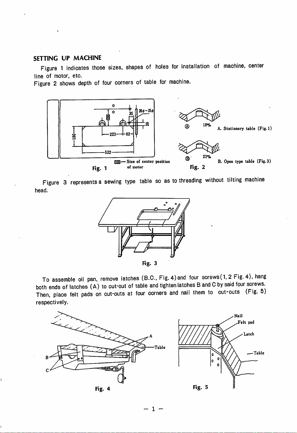
SETTING UP MACHINE
Figure1indicates
lineofmotor,
Figure2shows
etc.
those
depthoffour
sizes,
shapesofholes
cornersoftable
20<-25<J
for
machine.
for
installationofmachine,
18%
A. Stationary table (Fig. 1)
center
Fig. 1
Figure3representsasewing
head.
To
assemble
both
endsoflatches
Then,
place
respectively.
oil
pan,
remove
(A)toout-outoftable
felt
padsonout-outsatfour
]—
Sizeofcenter
of
motor
type
latches
position
23%
Fig. 2
tablesoastothreading
Fig. 3
(B.C.,
Fig.
and
tighten
corners
4)and
and
four
sorews(1,2
latches8and0by
nail
themtoout-outs
B. Open type table (Fig. 3}
without
tilting
Fig.
said
four
Felt
machine
4),
hang
screws
(Fig.
5)
pad
Table
Fig. 4
- 1 -
Fig. 5
Table
Page 6

Attach two L shape hinges(A, Fig.6) to
(B),
then,
push
the
the
machine
on
the
support
table.
plate
(a,
bed
side and
hook
Fig.7)downwardasfar
themtosemi-oiroie
as it
will
go
hinges
and
set
Caution:
When
putting
the
machineonother places
(a, Fig. 7) so as to keep the balance of the machine.
Fig. 6
Pass
order
the rope
1
to
3.
from
A to 8
and
Table
D
Oil
through
tank
the V
/
than
table,
shaped
pullupthe
Fig. 7
groove
0
support
and
plate
in the
(D
Fig. 8
- 2 -
(D
Page 7

OILING
Machine
has an automatic oiling mechanism, but, oiling points (Arrows, Fig. 9) are
provided for hand oiling for parts in movable contact which are not lubricated
reservior.
— .
Fig. 9
from
oil
Automatic
lubrication
system
(A) Automatic oiling system is composed of an oil reservior, holicw arm shaft and
hollow bed shaft through which necessary amount of oil is delivered to all of parts in
movable
contact, except these parts described in the
column
(B),
while
machine
is in
operation. Oil is distributed by centrifugal force through small jets.
The amount of oil flow, which should be slow, can be seen in the oil window (B,
Fig. 12), It can be adjusted with oil
When running in,
keep
speed
at
1,800
pump
(C Fig. 11) by opening or closing it.
to
2,500
R.P.M.
(B) Keep clean oil reservoir and pour oil in the reservoir (oil pan) up to the center
line (A, Fig. 10).
When
oil has been soiled for several months use, release it through the hole (B, Fig.
10) and pour new oil in the oil reservoir.
Page 8
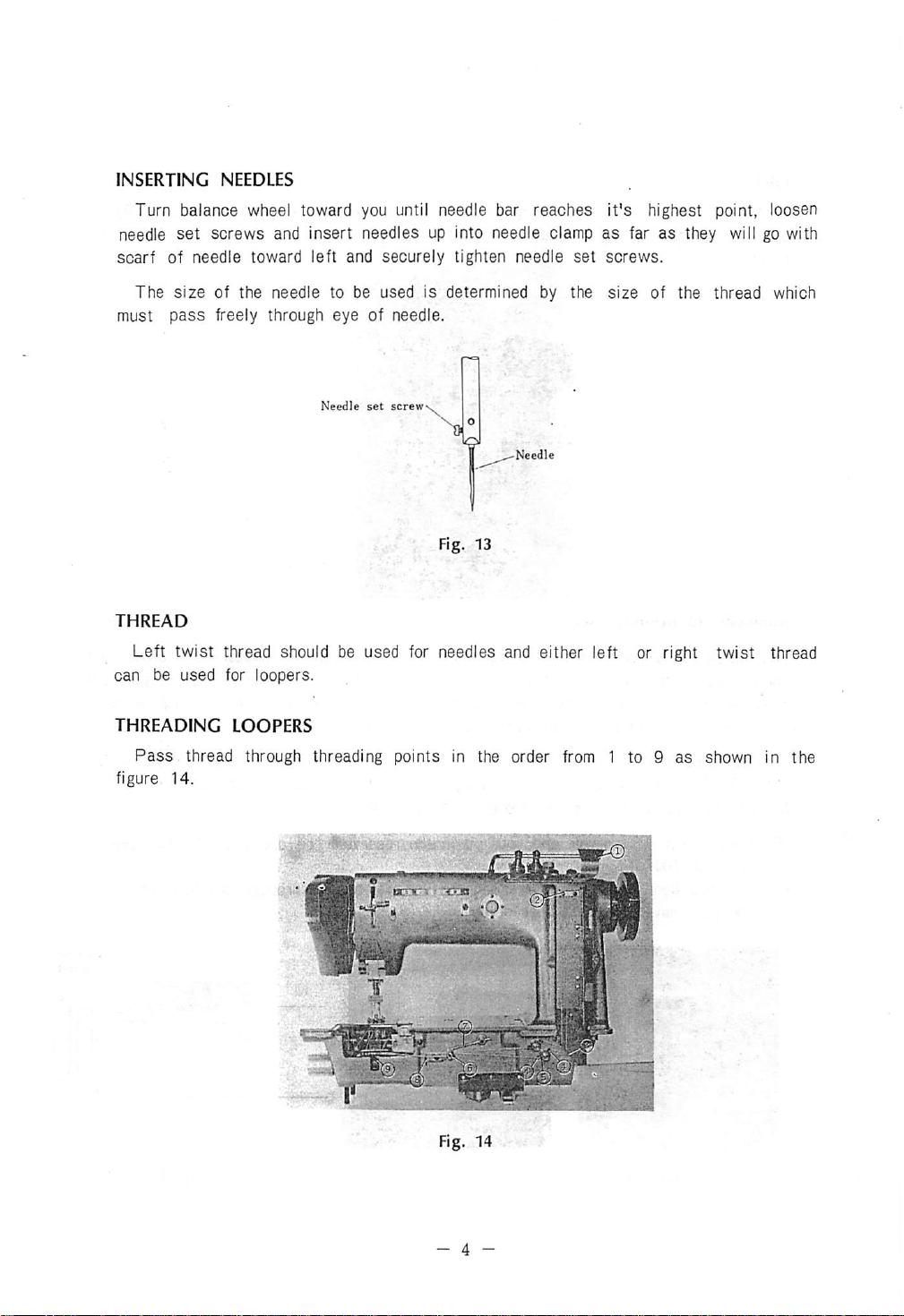
INSERTING
Turn
balance
needle
scarf
must
THREAD
can be
set
of needle toward left and
The
size
pass
Left
twist
used
NEEDLES
wheel toward you until needle bar
screws
and insert needles up into needle clamp
securely
tighten needle
of the needle to be used is determined by the
reaches
set
it's
highest point, loosen
as
far
as
they will go with
screws.
size
of the
thread
which
freely through eye of needle.
Needle
set
screw
Fig. 13
thread should be used for needles and either left or right twist thread
for loopers.
THREADING
Pass
thread through threading points in the order from 1 to 9
figure
14.
LOOPERS
Fig. 14
as
shown in
the
- 4 -
Page 9

Before threading further, turn balance wheel toward you soasto bring
wheel to the arm point as shown (B, Fig. 15),
the arrow and slightly turn it toward right, then loopers can move toward you.
will
make
threading
easier.
hold
the dial {Fig. 16)
letter
pull
it toward
M on the
This
Then,
pass
threads in the order from 10 to 12 and draw threads 50mm and
loopers, and return the dial to
threads.
THREADING
Pass
NEEDLES
threads through threading points in the order shown in the figure 18 from 1 to
Fig. 15
it's
original position. Be sure not to make
in
'"'g-
Fig. 16
pass
cross
10 and draw threads about 50mm. (Refer to Fig. 21 for threading tension-discs).
them
of
Hg.
18
- 5 -
Page 10

REGULATING
Tension
regulated
according to the material.
Looper
TENSIONS
should
..Needle
thread
be just
thread
pjg
enough
Perfect
to set the stitch in the material, and it
stitching
Imperfect
stitching
\
Fig. 20
Tight
of
tension
looper
should
''U
B ^
thread
Loose
of
needle
be
tension
thread
For more tension, turn the nuts (E, Fig. 21 and F, Fig.
and for
less
tension,
turn
them
toward
arrow
direction.
22)
toward'^arrow
direction,
m
f'g-
21
REGULATING
Always use the lightest pressure possible to allow higher working speed. It can be
adjusted
screw driver for
(B, Fig. 23). Before adjusting pressure, open the face plate (A, Fig.24) and
the distance between
it by the screw on the (B).
by
PRESSURE
turning
ON
MATERIAL
the regulating screw (A. Fig. 23)
more,
pressure, and for less pressure turn it toward^ arrow direction.
(B)
and
(C)
Fig. 24 is about 20mm. If it is not 20mm, adjust
toward
arrow
Fig.
direction
22
confirm
with
a
Fig. 23
- 6 -
Fig. 24
Page 11

ADJUSTING STITCH LENGTH
Numeral
length of stitch, turning parts (G, Fig. 25) toward right, at the same time turn balance
wheel over toward you until plunger enters a notch in adjustable eccentric on arm shaft.
Then, turn the
Now, press the button (11, Fig. 26) and at the same time turn balance wheel over to
ward you to increase length of stitch cr over
length
until it springs outwardly. Then, the machine is ready for operation.
numbersonthe stitch
(G)
1/4
turn.
on the stitch indicator.
indicator
Then,
show
the
number
from
you to shorten stitch, until desired
release the button (H) and turn the
of stitch per
inch.To
plunger
change
(G)
CAUTION:
After determination of the stitch length, adjustment for loopers (page
spreader (page 12) must be made.
ADJUSTING
The lift of vibrating and lifting presser foot is controlled by the wing nut(1, Fig. 27).
Loosen wing nut and raise it for higher lift or lower it for less lift, then securely tighten
the
nut.
Be sure to operate the
fM
Fig.
LIFT
OF
PRESSERS
machine
25
after the
plunger
(G) has
v.;
Fig. 26
-•
yes
sprung
10)
•" •"
outwardly.
and for
Fig. 27
- 7 -
Page 12

ADJUSTING
FEED
DOG
Itisthe
needle
is
The
at
the
parallel
plate
lowest
Adjustment
adjusting
After
30).
screw
the
correct
positionoffeeder
and
teeth
protrude
point.
1.5mm
adjustmentismadebythe
for
feed
height,
(B,
dog
loosen
Fig.
29)torighttoraise
has
correctly
the
nut
been
where
from
screw
(A,
set,
teethoffeeder
surfaceofneedle
(J,
Fig.
28)
Fig.
29)
and
the
the
feeder
securely
and
tighten
are
.parallel
plate,
tilting
machine
screw(H,
turnitto
the
nut
Rg. 28
with
when
head.
Fig.
30),
lefttolower
and
screw
surface
needle
turn
(H,
of
bar
the
it.
Fig.
NEEDLES
screws(A.
dog,
I||J^
Rg. 30
set
feeder
Fig.
32,C,Fig.
parallel
with
Rg.
29
TO
SET
FEED
DOG
Remove
adjust
of needle plate for feeder, then tighten feeder.
For more
is
necessary,
(J.
Fig.
Fig.31),
Fig.
position of feed bar. Then securely tight-
en
screws.
the
needle
so
that
needles
sideways
after
28),
remove
and
loosen
32)
and screw (C, Fig.32), and set
SIDEWISE
plate
enter
adjustment of feeder b
tightening
the
cover
position
{A,
Fig.
into
needle
the
plate
screw (B,
IN
RELATION
31),
screw
(B,
loosen
holeoffeed
TO
two
set
-|j|•J ^
m
^.
1
Fig. 31
27).
slots
.".jj
Page 13
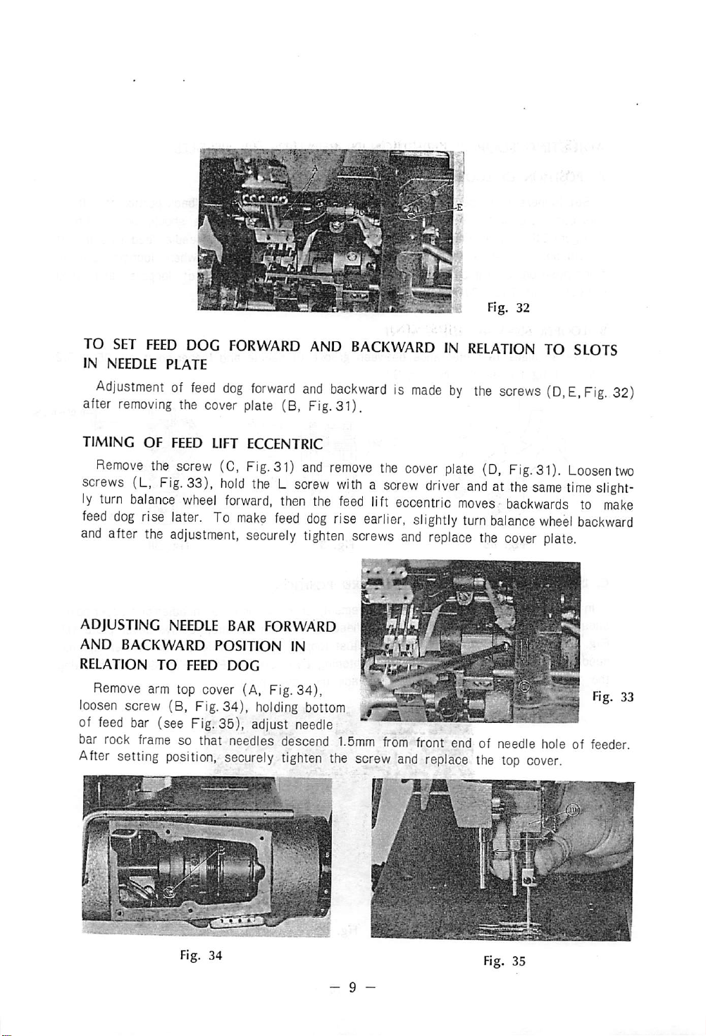
TO
SET
FEED
DOG
IN NEEDLE PLATE
Adjustmentoffeed
after
removing
the cover plate (B, Fig.31).
FORWARD
dog
forward
AND
BACKWARDINRELATIONTOSLOTS
and
backwardismadebythe
Fig. 32
screws
(D.E.Fig.
32)
TIMING
Remove
screws
ly
turn
feed
dog
and
after
of
feed
bar
rock
After
OF
FEED LIFT ECCENTRIC
the
screw
{L.
Fig.
balance
rise
later.
the
adjustment,
bar
(see'Fig.
frame
so that
setting
position,
(C,
33).
wheel
hold
forward,
To
make
Fig.31)
securely
theLscrew
then
feed
and
remove
withascrew
the
feed
dog
rise
tighten
lift
earlier,
screws
35),'adjust'needle
needles
securely
descend
tighten
1.5mm
the
screw
the
cover
eccentric
and
from
and
plate
driver
slightly
replace
front
replace
(D,
Fig.31).
andatthe
moves
turn
endofneedle
balance
the
the
backwards
cover
top
Loosen
same
time
to
wheel
backward
plate.
holeoffeeder.
cover.
two
slight
make
•
:;'Vv•
Mft
Page 14

ADJUSTING
A.
POSmON
LOOPERS
OF
LOOPERS
POSITION
IN RELATION
TO
NEEDLES
Set loopers to
this case, clearance between looper holder and
as figure 36 (only for
should be 0. Tighten
front position, clearance between right side surface of back of loopers and
deflector (M, Fig. 37) should also be
B. LOOPER SIDEWAY ADJUSTMENT
It is so
mm
C.
LOOPERS
In
made
and tighten screw (N, Fig.
loopers
shouldbesame
Fig.
31),
loosen
needlesbystrengthorweaknessoftightening
the
position,
looper
that clearance between
Fig. 36
FORWARD
forward
holder
compound
looper
AND
and
backward
(B. Fig. 36) slightly tilting their back
and
walking
set screws (C, Fig. 36). Further,
38).
BACKWARD
movement,
positioningroovesofneedles.
screw
tighten
the
(A,
screw
Fig.
39),
and
adjust
replace
bottom"
foot machine). For needle feed
1.5mm.
groove
Fig. 37 Fig. 38
of needle and
POSITION
crossing
To
loopers
two
the
cover
of loopers should be 0~1.5mm
when
looper
point
Feed
dog
^
pointofneedles
adjust
movement
screws
this,
remove
fasterorslower
(8.C,Fig.
plate.
portion
to left.
machine,
loopers are in
is 0.05 to 0.2
and
looper
cover
39).
After
points
plate
against
setting
In
it
loop
(D,
Fig. 39
-10
-
Page 15

Turn
balance
ance
wheel,
(Fig.41).
D.
NEEDLE
Turn
balance
center of needle, adjust so that right side of needle guard touches to side of
(Fig.
44)
loosen
GUARD
but
wheel
wheel
looper
toward
the
Fig. 40
toward
does
you.
screw
(D,
you,
not
touchtoneedle,
and
Fig.
when
align
39)
looper
the
and
point
set
points"
and
tighten
Needle
(B,
looper
are
guard
Fig.
40)
point
to the center of
Centerofneedle
Fig. 41
2.5mm
screws
and
arrow
(Fig.
42)
(A,8,Fig.
on
needles
from
43).
bal
the
needle
Fig. 42 Fig. 43
HEIGHT
OF
NEEDLE
Adjustmentismade
Fig.
46),
adjust
of
needle
eye is 2 to
needle
Fig. 45
BAR
after
locper
positionsothat
3mm
(Fig. 45)
position
has
been
the
measurement
by
two screws (B, Fig. 46).
-
11
-
determined,
from
looper
Fig. 44
open
face
pointtoupper
plate
Fig. 46
(A,
end
Page 16

LOOP
Tilt
47)
from
DEFLECTOR
machine
and
adjust
0.5mm
Looper
and
clearance
to
1mm.
turn
balance
between
wheel,
left
Driver
when
looperisin
sideofloop
front;
deflector
Loop
deflector \
and
Iccsen
right
screw
side
1%
(0,
of
Fig.
needle
Fig. 47
Adjust
SPREADER
Adjusting
of needle reaches to circumference of
sideofneedle
When
and
50)
by the screw"
loop
deflectorsothatitcomes
spreader
spreader
left
sideoflooperto0.2to0.5mmbythe
through
which
(0,
and
holder
point,
spreader
spreader
Fig.
48)
turn
balance
pointto1.5mmbyscrew
Spreader holder
Spreader sideway
is at
extreem
point
pass
from
0.5 to 2mm.
cut0to
wheel
looper
opreader
left
upper
Fig. 47-1
1mm
from
the
needle
toward
(A, Fig. 48), adjust measurement between
end,
adjust
portionofthe
®
screw
youtolower
(B,
Fig.
48).
Fig, 48
clearance
(0,
Fig.
between
48).
looper
needle,
Clearance
(Fig.
50) is
(Fig.
47-1).
when
spreader
adjusted
point
point
(Fig.
—
I—0.2-0.
Fig. 49
0.5-214,
Looper
Fig. 50
-
12
-
Spreader
Page 17

Tilt
machine,
(A,B.Fig.
right
for
smaller
curely tighten
To
decrease
adjustmentbyeither
loosen
51),
move
them
spreader
screws.
the'arnoum,'
lowering
spreader
driving
toward
stroke.
reverse
thread
eccentric
left
for
After
positionofspreader
the
take-uporraising
bigger
screw
spreader
the
and
thread
its
counter
stroke,
has
and
been
guide.
balance
move
them
determined,'
screws
toward
se
LOOPER
To
take-up
amountofthread,
ADJUSTING
Remove
lever
54)
right to open tension more, move the collar
toward left to open tension less.
Normally, opening of tension is 1.5mm
when
sition,
THREAD
increase
rod
arm
(A,
Fig.
on
collar
lifter lever
tighten
TAKE-UP
amountofthread,
(B,
Fig.
53) to left or
reverse
NEEDLE
54),
and
the
THREAD TENSION
top
cover,
loosen
move
the
works.
After setting
screw.
the
adjustment.
lower
screw
collar
move
move
Fig. 52
lifting
(C,
Fi'g.
toward
po-
looper
looper
After
thread
thread
the
RELEASER
-/SSSSSm
fi
//
guide
(A,
guide
downward.
adjustment,
Fig.
53)
securely
and
looper
To decrease
tighten
screws.
Fig. 53
thread
Fig. 54
-
13
-
Page 18

REPLACING
Turn
to
its
highest
adjustsothat
lower
shaft
with bed rim (D, Fig. 55) and is toward
arm shaft (see Fig. 55), in this position,
assemble
shaft
pulley.
balance
pulley
a
new
ARM
wheel to
point,
arrow
belt
SHAFT CONNECTING
raise
turn
mark
(A,
needle
lower
(B,
Fig.
Fig.
55)isparallel
to
arm
and
shaft
55)
bar
and
on
lower
BELT
9
9
^
^
Fig. 55
Fig. 56
ADJUSTMENT OF
Raise presser bar lifter (A, Fig.57). adjust
needle
after
adjust
12.5mm by guide lever screw,
plate
(B,
Adjustmentismade
removing
distance
Fig.
rubber
between
PRESSER
57)
and
through
stopper
the
HEIGHT
bottomoflifting
the
hole
(D, Fig.57)
from
hole.
position
guide
when
bottom of lifting presser reaches to needle plate.
SIDEWAY
FEET
Insert vibrating and lifting presser feet
into respective presser bar
will go, adjust so that they are parallel
and vertical against
and
feed
In
56).
measurement
presser
Lower
(A,
the
Fig.
ADJUSTMENT OF
as
farasthey
slots
of needle plate
dog.
this position, set screws (C,D, Fig.
foot
by
presser
58)
between
(C,
presser
bar
and
guide
Fig.
bar
lifter
upper
57) to
lifting
lever
surface of
bracket
(A,
(B,
8mm.
Fig.
PRESSER
screw,
Fig.
57),
58) to
km
Fig. 57
-
14
-
Fig. 58
Page 19

TIMING OF VIBRATING
To
set
positionoflifting
balance
to
cover
60)toleft,
movestoright,itbecomes
feed
wheel
dog,
plate
toward
after
(A,
then
youtolower
needle
Fig.
59),
vibrating
PRESSER
ecoentrio,
eye
has
loosen
presser
slower.
FOOT
lower
the
needle,
reachedtofeed
screw
foot
and
(A,
Fig.
reachestoneedle
presser
adjust
dog.
60),
bar
so
To
move
lifter
that
adjust
lifting
plate
(A.
vibrating
this,
eccentric
faster
Fig.
presser
remove
than
57).
reaches
(B,
needle,
turn
side
Fig.
if
Amountofliftofvibrating
equal
height. Adjustment is
presser
made
foot
and
by screw (B, Fig. 59).
Fig. 59
lifting
presser
foot
should
normally
be
Fig. 60
Page 20

GAUGE
3/16-
1/4"
1/4'-1/4"
1/4- 1/2-
3/4"
(3/16'to2")
(1/2"to2")
1/4' - 1/4' - 1/4'
5/16' - 5/16' -
3/8"-3/8"
1/2' -
1/4"-.1"
1/2"
- 3/8'
- 1/2'
- 1/4'
5/8-
5/16"
3/4-
MM"
(3/16"to2-)
L B X
l.
•
.l.•-t-
(A
=3/4'to2')
{B=3/16'.•Mimmum)
°-l
P-
A..•"•
1.
When
exchanging
A.toG
2.
When
mustbereplace
u
rohine'or
•
-^•r!:e:s=t[:rh::e
!a:Nnrne"dl"'harrusf'b:
4.
When
exchanging
bed
plate
-;Vr.;v••:,
Fig. 61
gauge
size.
accordingtothe
tranap
narts
vioeversa,
needle
needle
and
bed
plate
c ^^
for
instance
0,
four
thread
re"aoe"
guage
slide
mustbereplaced.
iradditrrthrs/Tarts'lnTionrd
to
size.
from
needle
tension
A.
Needle
B. Needle clamp
C.
Vibrating
D.
Lifting
e.
Needle
p.
Feed
bar
presser
presser
plate
dog
^
thread
foot
guard
foot
in
the
-16-
 Loading...