

Page 1

OPERATING
INSTRUCTIONS
FOR
JW-8BL-20
JW-8BL-30
JW-28BL-20
JW-28BL-30
SEIKO
SEWING MACHINE CO., LTD.
TOKYO
JAPAN
Page 2

OPERATING
This
is a
guidetouseofSEIKO
duty
materials sewing machine
mechanism,
Please read
under
this
INSTRUCTIONS
the
guide
Specifications
MAX. SPEED (s.p.m.)
MAX.
STITCH
MAX.
LIFTOFFOOT
NEEDLE
BOBBIN
WORKING
BED
DIMENSION
POWER
MOTOR
(mm)
SIZE
(mm)
SPACE
REQUIRED
PULLEY
(mm)
(mm)
(W)
DIA.(mm)
NET/GROSS WEIGHTSM^
MAX.
SPEED
MAX.
STITCH
MAX.
LIFTOFFOOT
NEEDLE
BOBBIN
WORKING
BED
DIMENSION
POWER
MOTOR
NET/GROSS
NEEDLE
(s.p.m.)
(mm)
SIZE
(mm)
SPACE
REQUIRED
PULLEY
WEIGHTS
SPACING
(mm)
(mm)
(W)
DIA.(mm)
JW series
with
compound
best
condition.
thoroughlysothat
JW-8BL-20 JW-8BL-30
(mm)
DY X3 (sandard No. 24) •
508X153
846X230
JW-28BL-20 JW-28BL-30
(mm)
DY X 3
508X153
846X230
M^
3/16"
(4.7
mm),
SEIKO
model
JW
SERIES
long-arm high
speed
feed and walking
you
may
expect
SINGLE
1,600
NEEDLE
10
20
good
performance.
SY5213.794
37?>x 13
762X153
1,100x230
400W,2P
7Oi'^/
6O0 (50/60HZ)
109/kgs. 151/kgs. 0.377/M3
TWIN
NEEDLE
1,500
10
20
(sandard
60^/509*
112/kgs.
2-3/8"
No.
24)•SY5213•794
37^.x
13
400W,
2P
(50/60HZ)
154/kgs.
(60
mm).
Standard
762X153
1,100x230
0.377/M3
1/4"(6.4mm)
MODEL
for
foot
feeding
heavy-
CODE
EXPLANATION
J :
Jumbo
W :
B :
L :
USE
Tent,
Plate,
Horizontal
Reverse
Large
Hook&Bobbin
FOR
Sail
Clodi,
Leather,
(Super
Hook
Stitch
etc.
Long
Arm)
Rubberized
8 : Single-Needle
20:
508
mm
28:
Twin-Needle
30:
762
mm
Fabrics, Heavy
with
(20
inch)
with
(30
inch) Working
Synthetic,
Compound
Working
Compound
Heavy
Upholstery
Space
Space
Feed
Feed
& Walking
& Walking
Materials,
Foot
Foot
Fiber
Page 3

—
INDEX
CONTENTS
Page
Setting up
Caution before starting
the
machine 2
the
operation
Oiling 2 —3
Needle
Thread
Winding
Removing
Threading
Regulating
Adjustmentofthe
Adjustmentofthe
Reverse stitching 6
the
lower
threadonthe
and
inserting
the
needle 5
the
thread
the
tensions 5
stitch
pressure 6
bobbin
bobbin
1
2
3
4
4
4
6
INSTRUCTIONS
Relative
and
positionofvibrating
the
needle
Adjustmentofthe
Timing between
Adjustment
the
of bobbin case
Adjustmentofthe
Timingofthe
Adjustmentofthe
Adjustmentofthe
Replacementofthe
To
re-engage
vibrating
the
Adjustmentofthe
Adjustmentofthe
Treadle
assembly
FOR
ADJUSTMENT
holeofthe
heightofthe
hook
heightofthe
and
clearance
thread
safety
controller
connection
clutch
built-in
oiling
for
complete
and
lifting presser bar, also,ofthe
feeder
needle
feed dog 7
and
the
needle 8
opener
presser
lifting presser
for
the
belt
bobbin
the
hook
set
feet
feet
vibrating
spring
and
lifting presser
feet
winder
saddle 14
11-
7
9
9
10
10
11
12
13
14
15
Page 4

SETTINGUPTHE
Setting
bolts
(A)
up
under
the
MACHINE
machine on
the
bed.
(Fig.1)
the
table
after
removed
two
pieces of
supporting
CAUTION
1. Do
not
has
been
During
2.
The
machine
(The
auxiliary
3. Do
OILING
not
operation.
ting
speed
casebycase.
(Figs.2,3,4&5)
1. Oil
shouldbeappliedateachofthe
4&5.
BEFORE
operate
properly
practice
opearate
To
aretobe
STARTING
the
oiledatevery
period
pulley
hand
turns
wheel
the
take
THE
OPERATION
machine,
the
even if
spot
new
machine
towardtothe
only
and
turnstoclockwise.)
machineatmaximum
practice
changedtoproper
operation
condition
place
for
testing
reservoir
shouldbeoiled
operator.
andoridling, unless it
required
speedof1,500
at
speed
of
1,000
suitable
designatedbyarrows
lubrication.
more
s.p.m.,
s.p.m.,
for
the
frequency.
for
starting
but
materials
in Fig. 2,
opera
in
3,
Page 5

2.
To
fill
the
oil
oil gauge (Fig. 6 A)
reference
Whenincontinuous
3.
lineofthe
/ ;ji« H
I.--
for
reservoir
and
of
pour
oil gauge (Fig. 6-1 B).
use, it
shouldbeoiledatleast
hook
the
I,.
Ilf
saddle
oil until
Ik/
from
the
hole
after
taken
out
the
the
oil level reachedtothe
upper
twiceaday.
NEEDLE
1.
2. To insert
(Figs.7 & 8)
SEIKO
(standard
The
type
needle
JW
series
machines
No.
24)•SY5213•794.
size of needle to be used should be
and
thicknessofthe
the
needle,
bar
movesupto
barasdeeplyasit will go,
(28BL).
Tighten
the
needle
set
IT'
S
"I
'J.
are
sewing
turn
the
its highest
with
screw
setupto
use
determinedbythe
materials.
machine pulley over
point,
the
securely.
put
long
grooveofthe
standard
the
Fig.
6-1
needleofDY x 3
sizeofthread,
toward
needle up
needle
you until
into
faced
the
the
needle
outside
Page 6

THREAD
Normally, left twisted
(Fig.9)
thread
side needleoftwin-needle
right
twisted
thread.)
Left
Twist
Is used
for
upper
(needle) thread. (But, for left
288Lmachine.Itcanbefinished
Right
Twist
in fine results
with
WINDING
1. Pass
which
2. Press
matically,
The
thread.
REMOVING
1. Draw
latch
2. Insert
THE
LOWER
the
thread
setupto
the
lever
In engage
bobbin
X 3
AND
back
the
(2)toa vertical
the
bobbin
hinged latch (2) and
3.
When
closing
through.
THREADONTHE
through
the
shaftofbobbin
(6)toarrow
with
will
automatically
^ o .
INSERTING
side
plate
position,
and
draw
the
side
plate
(1) - (4),
direction,
the
operationofthe
-i
Fig.
10
THE
BOBBIN
(1)onthe
then
pull
thread
the
thread
(1), leave
BOBBIN
and
winder.
be
stopped
bedofthe
remove
out
end
just
wind
then
(Figs.
about
(Figs.
several
(5)
the
machine.
after
12 &13)
and
4—5cm(3),
under
enough
10 &11)
times
bobbin
the
machine,
insert
the
tension
space
winds
bobbin
-
3^-
the
for
arround
the
X A
and
raise
bobbin.
then
push
spring (4).
the
threadtopass
the
thread
is filled
the
down
bobbin
auto
with
hinged
the
Page 7

THREADING
1. Pass
the
THE
thread
NEEDLE
from
thread
guide (1) -
eyeiet
(2) - tension disc (3) - tension
thread guide (4) - guide (5) - thread take-up spring (6) - guide (7) - take-up
lever (8) - guide (7) - lowerguide (9) - self threading needle bar thread guide
(10) -
through
(Remark) Wind
2. With
the
the
eyeofthe
the
thread a single timetotension thread guide (4).
needle (11),
left hand hold the end of
the
needle thread leaving it slack from the
hand to the needle. Turn the machine pulley over toward you until the
needle moves down and up again to itshighest point,
thus
catching
the
bobbin
thread, draw up the needle thread, and the bobbin thread will come up with
it through
feet
and
the
close
hole in
the
slide.
the
feed dog. Lay the threads back under
the
presser
St
REGULATING
THE
1. The tension on
2. The tension on
spring on
To increase
the
tension,
the
outsideofthe
the
turn
THREAD
the
the
tension,
over
TENSIONS
(Figs.
needle thread is regulated by
bobbin thread Is regulated by
bobbin case (Fig. 17 A).
turn
over
nutorscrew to
nutorscrewtothe
Fig.
16
16 &17)
left.
the
w
7
thumb
the
the
nut
(Fig. 16 A).
screwofthe
right, and to decrease
tension
Page 8

ADJUSTMENT
The
lengthofstitch
while
turning
setting
To
decrease
When
confirmed
the
increase
the
the
topofbutton
desired
releasing
OF THE
STITCH
LENGTH
is regulated by pressing
the
machine
pulley
(1)tothe
the
lengthofstitch,
lengthofstitch,
lengthofstitchisobtained,
the
button
turn
(1)tothe
(2)
turn
the
(Fig.18)
slowly
feed
the
machine
down
with
eccentric.
machine
pulleytoopposite
operate
original
the
button
right
handinthe
pulley
the
position.
(1)
over
toward
machine
Fig.
19
with
left
condition
you.
direction.
after
hand,
of
To
fully
ADJUSTMENT
The
pressureofthe
To
increase
screwtocounter-clockwise.
REVERSE
The
chain
lever
(A)
To
feed
anddonot
OF THE
the
pressure,
STITCHING
for
the
underneath
the
work
stoptopress
PRESSURE
presser
(Fig. 20)
feed reversing pedal is
of
toward
feet
turn
the
bedofthe
you,
down
(Fig.19)
is regulated by
the
screw to clockwise, and decrease it,
machine.
press
down
on
the
way.
the
adjusting
connectedtothe
firmly
on
the
screw.
hookoffeed
feed
reversing
reversing
turn
the
pedal,
Fig.
20
Page 9
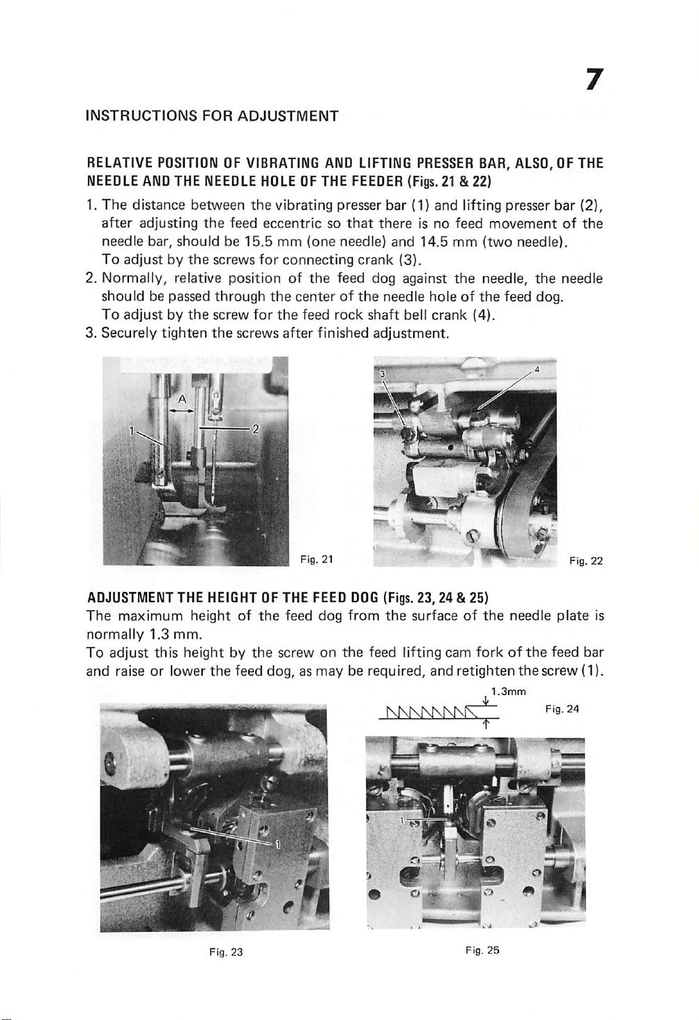
INSTRUCTIONS
FOR
ADJUSTMENT
RELATIVE
NEEDLE
1.
The
after
needle
To
POSITIOlU
AND
THE
distance
between
adjusting
bar,
should
adjustbythe
OF VIBRATING AND LIFTING PRESSES BAR, ALSO, OF THE
NEEDLE
the
screws
HOLE
the
vibrating
feed
eccentricsothat
be
15.5
mm
for
connecting
2. Normally, relative position of
should
To
3.
Securely
be passed
adjustbythe
tighten
A I.
through
screw
the
screws
for
the
the
after
OF THE
(one
the
FEEDER
presser
needle)
crank
feed dog against
centerofthe
feed
rock
finished
(Figs.21 &
bar
(1)
there
is no
and
14.5
(3).
needle
shaft
bell
adjustment.
22}
and
lifting
feed
mm
(two
the
needle,
holeofthe
crank
(4).
presser
movement
needle).
the
feed
dog.
bar
of
needle
(2),
the
ADJUSTMENT
The
maximum
normally
To
adjust
THE
height
1.3
mm.
this height by
and raiseorlower
HEIGHT
of
the
feed dog, as
OF THE
the
the
screw on
A»*
1 t
\mii\l~T
rT
uJ-'
feed
: "Vr
FEED
DOG
(Figs.
23,24
dog
from
the
surfaceofthe
the
feed lifting cam
may
be required, and retighten
NKNNKNKfV
& 25)
forkofthe
1.3mm
^
needle
thescrew
F'S-
plate
feed
is
bar
(1).
24
Page 10

TIIVlliyG
Set
length
1. If
BETWEEN
the
feed
eccentric
between
the
needle
will
beatthe
from
the
lowest
For
the
adjustment
tap
this gear to
shaft
until
the
Tappingtothe
hook
timing.
Except
driving gear (2)
Securely
ment.
the
above case, to adjust in changing gear
tighten
THE
HOOK
with
vibrating
bar
and sewing
center
of
point.
of timing, loosen 2 screws (1) for
the
rightorleft in clearanceof2 mm on
pointofthe
right gives
and
hook
the
2 set screws
and
the
2. Normal clearance between
AND
THE
NEEDLE
the
buttonatno feeding
lifting
presser
hook
are correctly timed,
needle
hookIsat
on
shaft
hook
when
earlier
gear (3).
for
point
the
hook
hook driving gear
and scarfofthe
(Fig.26)
position,
bar
shouldbe15.5
the
needle
centerofthe
timing,
andtothe
condition
the
raised
hook
needle.
after
needle is In
and
confirm
mm.
pointofthe
3.8
mm±0.5
driving gear, and
the
hook
driving
left gives
between
finished adjust
0.02
the
hook
mm
later
hook
• 0.1
(1) Loosen
hook
two
saddle.
screws (4)
and
(2) Move hook saddle to right or left,
as
may
be
point
sible
(3)
Then
(4)
To
attention
adjustment.
3. Height of
Normal
eye
of
2.2
mm.
In case
set, loose
stud
pinch screw (A)
needle
quired
(A).
above,
required,
is as closetoneedle as
without
striking
securely tighten
check
the
bar
the
free
the
needle
clearance
needle and
the
needle
the
needle bar connecting
in
correct
then
needle
from
bar
between
bar
retighten
until
it.
two
with
bent
(Fig. 27).
topofthe
hook
point
is incorrectly
and
place
position
the
(5)
for
hook
pos
screws.
careful
before
the
as re
screw
'A
is
Fig.
26
Page 11

ADJUSTMENTOFBOBBIN
1.
Turn
the
machine
openerislocatedatthe
CASE
pulleyorhand
distance
2. In this position, adjust it so
opener
3.
Securely
(A)
tighten
and
the
topofthe
the
screw (B)
. . f r
..:
Fig.
28
OPENER
(Fig.28)
wheel
from
that
the
clearance between
hookisabout
after
finished
(Fig. 31 D & E)
the
needle
0.3-0.8
adjustment.
plate.
until
the
mm.
13
Fig.
the
topofthe
inside edge of
29
the
ADJUSTMENTOFTHE
Normal
ser
When
lever
1.
2.
3.
Position
by
position
distance
footatstopped
step
(B).
To
change
above
condition.
The
height
presser
Normal
(Dar
the
bar
distance
position guide (4) is 7 mm.
of
screw (2)
guide
on
the
the
of
lifting
the
bracket.
between
lifting
relative lift
lift of
vibrating
for
HEIGHTOFTHE
the
surfaceofthe
positionofthe
pedal,
of
the
presser
bracket.
between
presser
presser
presser
bar
PRESSER
needle
stop
lever
(C) is19mm.
the
stop
lever (C) willbereleasedbythe
the
presser
feet,
feetisadjustable
bar
position
foottoshiftinleft
lifting
bracket
and
FEET
guide
(Figs.
plate
loosen
by moving
bracket
and
the
screw (5)
29,30 & 31)
(A)
and
vibrating
the
screw (1)atthe
the
(3)
and
rightistobeadjusted
for
pres-
lifting
screw
presser
presser
I .^v.
of
bar
'it.--
Fig.
30
Page 12

10
TIMING
The
should
being
OFTHE
amountofliftofthe
be
sewn.
VIBRATING
regulated
accordingtothethickness
AND
LIFTING
vibrating
PRESSER
and
lifting presser
FEET(Fig. 32)
of
materials
feet
The feet should lift just enoughto clear the materials. 0
As a rule,
an
equal
they
To
change
screw (A)
ting
securely
the
vibrating
height,
liftanunequal
presser
tighten
but
the
relative liftofthe
for
lifting
bar
the
some
height.
rock
upward
screw (A),
and
lifting presser
gradesofwork
shaft
crank
or
downward
feet
should
may
require
presser feet, loosen
and
move
the
vibra
as
required,
lift
that
the
then
9
© o
%
Upper
Fig.
Surface
32
ADJUSTMENT
FEET (Fig. 33)
PRESSER
The
ser
To
increase
to
the
The
imum,sothat
als
The
by
amount
feet
aretobe
decrease
the
required
clearance
being
sewn.
timing
Fig.
32.
FEET-Fig. 32)
position
DF
THE
CLEARANCE
(RE-ADJUSTMENT
of
the
liftofthe
adjustedbythe
the
movementinsetting
movementinsetting
position,
for
the
vibrating
the
clearanceofthem
for
the
alternating
securely
and
vibrating
FDR
THE
VIBRATING
THE
TIMING
feed
lifting bell
the
tighten
lifting
shouldbeadjusted
and
crank
the
stud
stud
(1)atthe
the
stud
presser
lifting presser
OF THE
for
the
link screw
(1)atthe
(1)
feet
AND
VIBRATING
vibrating
stud
upper
lower
position.
with
nut
are
being
accordingtothe
feet
should
LIFTING
and
position,
(2).
adjustedatmax
PRESSER
AND
LIFTING
lifting
(1).
and
After
setting
materi
be regulated
pres
to
Page 13

ADJUSTMENT
1.
For
more
of
the
2. To strengthen
OF THE
controller
controller
the
spring stud screw (4) at
slightly to
and
securely retighten
the
left with a screwdriver,orlighten its
THREAD
actiononthe
and
set
the
action of
the
the
CONTROLLER
thread,
stop
lever, and
the
controller spring on
rear of
spring
the
stud
SPRING
loosen
for
the
less
stop screw and
screw.
(Fig.34)
set
action
the
turn
action
screw (1) at
set
the
stop
thread, loosen
the
spring stud (5)
turntothe
the
higher.
Fig.
right
the
right
34
REPLACEMENT
A.When
placing
the
purposesofthe
lowings: (Figs.
1.
Turn
the
at
the
2.
Turn
the
driving
ing
shaft
the
upper
OF
THE
connection
35&36)
machine pulley
highest
shaft
position.
hook
bushing
bushing
and
lower
shaft
CDNNECTIGN
belt
removed
parts,itshould
toward
with
the
collar
(1)
are
directly
pulley.
(2)
BELT
fingers
and
from
the
be
replaced
yousothat
until
the
red
In line.
Then
pulley
placed
the
point
for
adjusting
by
the
the
take-up
arrow
mark
markonthe
replace
the
andorre
processes, as fol-
lever (A)
on
the
hook
hook
driv
belt
over
the
Fig.
Fig.
35
36
Page 14

12
B. Replacement of
1.
Remove
2. Slide
the
3. Loosen
the
machine pulley (3),
4. Loosen
ing (6).
5. Lift
the
the
the
upper
connection
the
machine pulley
the
three
belt up through
far as possible and draw it
the
bushing.
6. Replace
7. Securely
looseness.
the
connection
tighten
connection belt when damaged. (Figs. 37 & 38)
arm
plate
and
reservoir.
belt
(A)
off
then
screws in
all
the
screws, so astofit
from lower
adjustment
remove
the
the
arm cap hole after removed
out
arm
through
the
shaft
beltasopposite
and
upper
screw (2) and
belt
two
pulley,
set-screws
machine pulley.
bushing (5) and remove
the
bushing (6) as
the
space normally occupied by
processes as above for removing it.
the
arm shaft, firmly, free from
the
for
bush
I- • - < /
Fig.
Fig.
37
38
Page 15

13
TO RE-ENGAGETHE SAFETY
The
hook
driving
the
hook from getting
shaft
pulley prevents damage in
releasing
Take
1.
the
locking lever in
out
jammed
thread
and
out
CLUTCH
the
of time.
the
the
from
(Figs. 39 & 40)
shaftofthe
The
sewing
hook
are spllnedtoprevent
safety clutch located In
the
lower belt
event of thread jamming in the sewing hook by
pulley.
the
hook.
2. To re-engage the clutch, press down the lock stud (A), near the base of
arm by left hand and
then
the
safety
the
3. In
(B) for lower
To increase
the
case easily releasing
belt
the
pressure in
turn
the
machine pulley backward slowly by right hand,
clutch
willbereleased.
the
pulley
after
removed
pressure in turning
turning
the
screw (B)tocounter-clockwise.
safety
clutch,
the
adjust
connection
the
pressurebythe
belt (C).
screw (B)toclockwise andtodecrease
the
screw
Fig.
39
Page 16

14
ADJUSTMENT
Adjust
for
Remove
for
or
the
volumeofwinding
the
winderinturningittoupand
the
the
winder
left.
OF THE
plate
by
BUILT-IN
(2)onthe
the
winder
BOBBIN
threadtothe
frontofthe
driving gear (3) in
WINDER
down.
arm
u o 'l
V
(Figs.41 & 42)
bobbinbythe
and
adjust
the
arm
.V
adjustment
the
slipageofthe
shafttoshifting
screw (1)
shaft
right
ADJUSTMENT
Loosen
the
oil adjustment dial (2). Maximum oil supply at
point
mark (1)
oil
supplyatthe
the
OF THE
screw
on
OILING
for
the
the
vertical
FORTHE
oil
adjustment
hook
saddle
positionofthe
and
HOOK
dial (3)
the
center
SADDLE
and
center
lineofthe
(Fig.43)
adjust
line of
oil
the
directly in line of
the
dial (2).
supplybyturning
dial (2).
Stop
the
the
Page 17

15
TREADLE
a.
Construct
b. Chain 1 , 2 , 3
ASSEMBLY
treadle
are
COMPLETE
assembly
strained
c. Chain 3 is hooked crank
the
hole
drilled
Chain 3 is used as
stand
horizontal
stoppertoprevent treadle 4 is
d. Screw 6 is drived tightly
complete
tightly.
one
side, and
after
crank
SET
setasshown.
plate.
set up
the
other
correctly.
hook of chain 3 is
not
hit
by camfollower.
dinged
CompletionofTreadle
Set
Page 18

-MEMO-
 Loading...