

Page 1

1
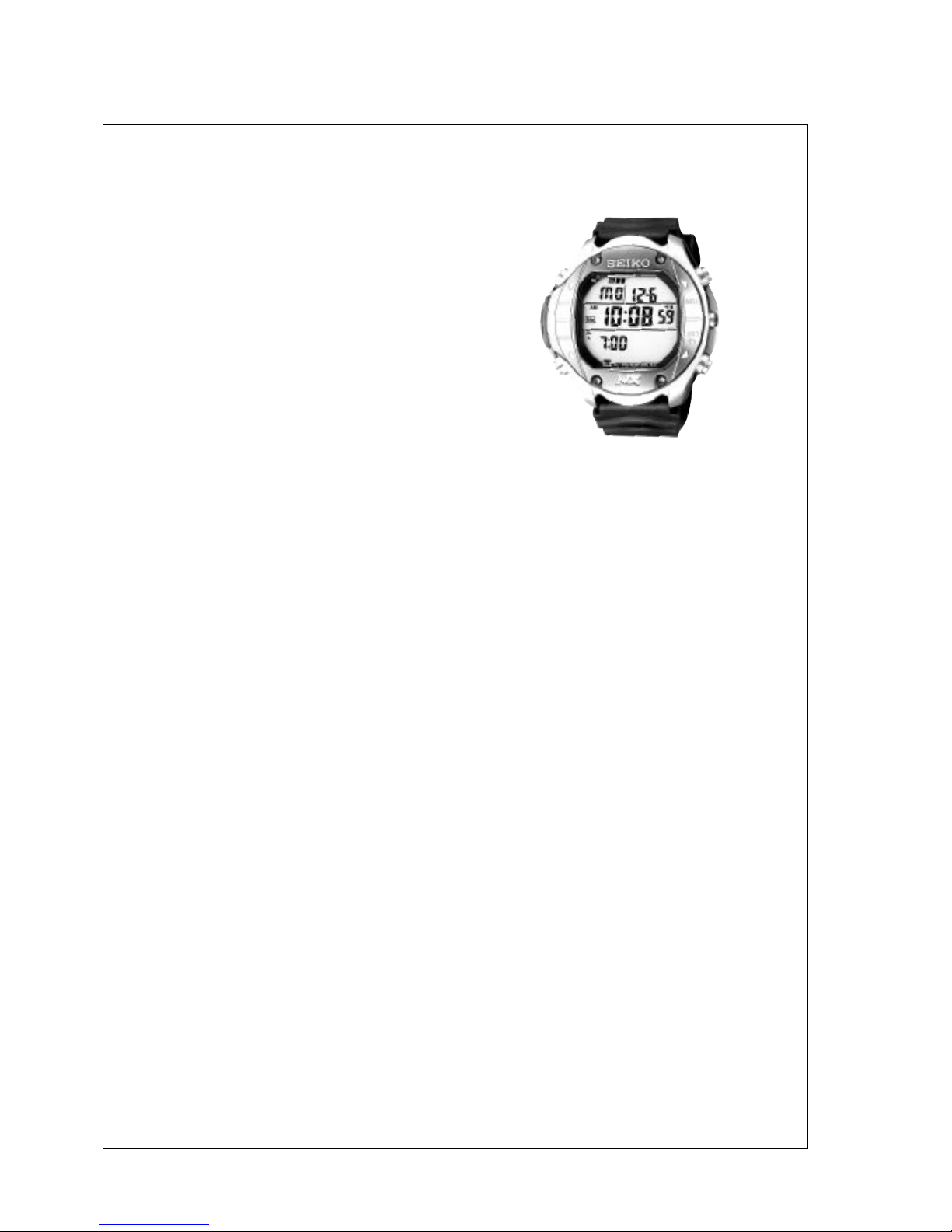
PARTS CATALOGUE / TECHNICAL GUIDE
Movement
size
Cal. No.
Item
DH33A
Movement
(x 1.0)
Outside diameter
Casing diameter
Height 9.0 mm
ø36.2mm
Display Medium Neumatic Liquid Crystal, FEM (Field Effect Mode)
1/5 Multiplex driving systemLiquid Crystal Driving System
Battery
Lithium battery SEIKO CR2032
Voltage : 3V
Battery life is approximately 3 years
Measuring Gate by Quartz Tester
Any gate can be used
Loss/Gain
Regulation System
Monthly rate at normal temperature range: less than 15 seconds
Trimmer condenser
• DIVE PLAN display
• Daily Alarm function
• NITOROX Diving function
•Dive Plan function
• Dive Log function
• Hour Correction function
• Dive function
• Warning Alarm function
• Battery Life indicator
• EL Backlight
• TIME/CALENDAR display
• REGULAR ALARM display
• Dive mode display
•FO
2
(NITROX) display
• DIVE PLAN display
• HOUR CORRECTION display
•DIVE LOG display
Additional Mechanism
Display System
Cal. DH33A
[SPECIFICATIONS]
( For Movement Replacement )
Page 2

2
• The movement parts are not provided.
• The rotation movement code is
UDH3320,which includes the parts 4
to 9 .
PARTS CATALOGUE
Disassembling procedures Fig. : 1 10
Reassembling procedures Fig. : 10 1
Lubricating: Types of oil Oil quantity
Silicone grease 500,000 c.s. Normal quantity
Cal. DH33A
➔
➔
➡
Please refer to “II. REMARKS ON DISASSEMBLING AND REASSEMBLING”.
1 Case back screw
Piezoelectric element
2 Case back
5
6 Module
10 Case
Button C
Button D
Gasket for sensor unit
Sensor
3 Case back gasket
4Screws for sensor unit
mounting plate
8 Sensor unit clamp
9 Sensor unit
Button spring clip
Button A
7
Button B
Structure of the sensor unit
Sensor ring
Sensor unit
mounting plate
Screws for sensor unit
clamp
Page 3

3
TECHNICAL GUIDE
Cal. DH33A
I. REMARKS ON BATTERY CHANGE
When changing the battery, follow the procedures below.
<How to remove>
1. Remove the comment seal.
*Check where the comment seal was put, as it must be put
back to the same place.
2. Release the battery clamp hooking portion with a pair of
tweezers as illustrated at right.
3. Remove the battery.
<How to install>
1. Set the new battery.
2. Set the hooking portion of the battery clamp firmly.
3. Put the comment seal back where it was originally put.
4. Reset the circuit by pressing down the AC terminal of the
circuit block and the circuit block cover with a pair of conductive
tweezers.
Battery clamp
hooking portion
II. REMARKS ON DISASSEMBLING AND REASSEMBLING
● Remarks on the adhesive
• The case back screw is fixed by using the adhesive.
• Use the “LOCTITE 241” of Loctite Corporation to fix the screws.
• Never use any other adhesive but “LOCTITE 241” in the market place or any joining material for band
adjustable screw (S-312), otherwise it may cause difficulties when unscrewing or poor water
resistance when screws become loose because of some unexpected shocks.
● How to glue and fix the screws
1. Remove water drops, oil contents, dust and dirt from the
screw and screw hole on the case.
2. Apply appropriate amount of the adhesive to a screw as
illustrated at right.
3. Tighten up the screw securely with a torque driver (bit size:
T5).
4. Leave them for approximately 24 hours under normal
temperature so that the adhesive becomes dry enough and
the screws get fixed securely.
1 Case Back Screw
• When tightening the screws up, tighten the screw one after
another in diagonal order.
• After tightening up all the screws, retighten all of them once
again to fix them even more securely.
Adheshive
Page 4
4
TECHNICAL GUIDE
Cal. DH33A
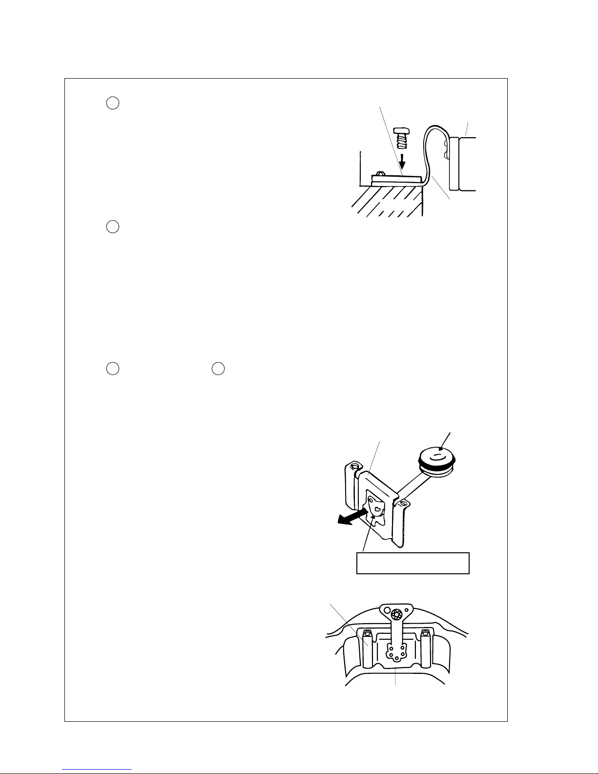
5 Sensor unit mounting plate
• Set the sensor unit board to the inductive portion
of the module, on which place the sensor unit
mounting plate. Then screw them up tightly.
89Sensor unit
❖ The sensor unit and module are provided in pair with their accuracy pre-adjusted. Therefore,
even in case for a defect of the either one, replace both the sensor unit and module as one
set.
<How to install>
1. Remove dust and dirt from the sensor unit
of the case.
2. Pass the sensor unit board through the
hole of the sensor unit clamp toward the
direction shown in the illustration at right.
(Bend the tip of the sensor unit board while
passing it through the hole.)
Caution
• Never touch the gel portion of the sensor.
3. Set the sensor unit firmly to the set position
of the case.
4. Put the sensor unit clamp into the groove
portion of the case ("A" portion in the
illustration at right), then screw it up
securely.
Sensor unit mounting plate
Module
Gel portion
Bend the sensor unit board
while passing it through the hole.
"A" Portion
Sensor unit clamp
Sensor unit clamp
Sensor unit clamp
6 Module
❖ The module and sensor unit are provided in pair with
their accuracy pre-adjusted. Therefore, even in case for
a defect ofthe either one, replace both the module and
sensor unit as one set.
Caution
• Be careful not to damage the sensor unit board.
• Do not touch the trimmer for the accuracy adjustment.
Sensor unit board
Sensor
Page 5
5
TECHNICAL GUIDE
Cal. DH33A
IV. VALUE CHECKING AND ADJUSTMENT
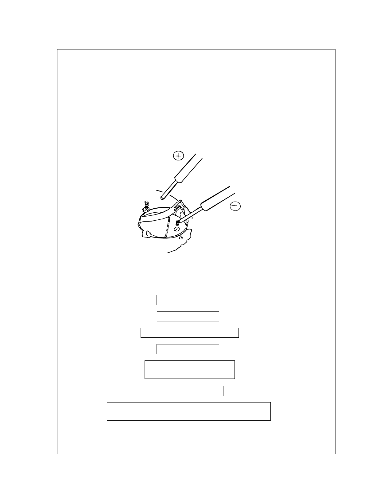
● Current Consumption
For the whole module (in the WATCH mode) : Less than 2.5 µA (With 3.0 V. supplied from a battery)
<How to measure the current consumption>
1. Remove the lithium battery and connect the tester as illustrated below.
2. With the tester connected to the movement, reset the circuit.
(To reset the circuit, refer to “I. Remarks on Battery Change”.)
3. When stable measurements can be obtained, read the measurement.
● Functional Checks
After replacing module with a new one, Cal.DH33 requires checks for the accuracy of data such as 1: water
depth measurement, 2: pressure index value and 3: temperature measurement . Those checks should be
performed in the TEST mode.
Check if all the segments light up
Check if EL backlight light up
Check temeperature
Check atomospheric pressure value
Close the case back
Go to the TEST mode
▼
▼
▼
▼
▼
▼
▼
In the Atmospheric pressure/Water depth mode, check the
accuracy of water depth measurement and water resistance
Press Button D in the Buzzer mode to return to the
normal TIME/CALENDAR display and set the time.
Check if the buzzer rings
Functional check procedure
Page 6
6
★ While in the All-Segments-Light-Up mode, if Button D is pressed , EL backlight illuminates the
display for 2 to 3 seconds.
★★ While in the Buzzer mode, if Button C is pressed, the buzzer rings for 5 to 6 seconds, and if Button
D (SET button) is kept pressed for 5 to 6 seconds, the display returns to the normal TIME/
CALENDAR display.
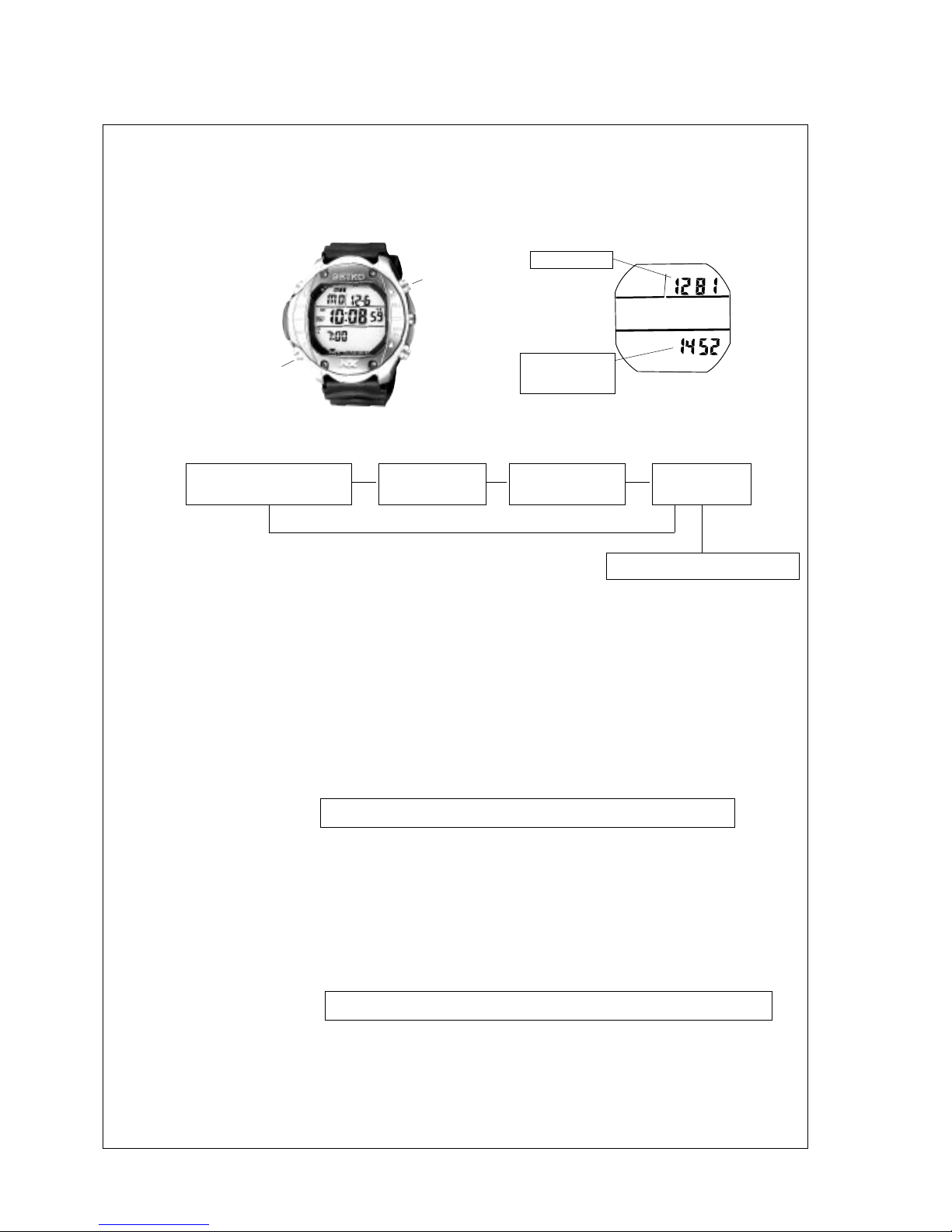
2. Pressure Sensor
● Remarks on atmospheric pressure
Pressure index value is determined by the following calculation.
Pressure index value = Output value from sensor – Offset value
In the case of the display in Illustration 2,
Pressure index value = 1452 – 1281 = 171
so the pressure index value is 171.
In order to calculate the atmospheric pressure out of the pressure index value, the caluculation is
as follows.
Atmospheric pressure (hPa) = ( Pressure index value + 5 ) x 2.5 + 550
In the case of the display in Illustration 2,
Atmospheric pressure (hPa) = ( 171 + 5 ) x 2.5 + 550 = 990 (hPa)
so the atmospheric pressure is 990 hPa.
TECHNICAL GUIDE
Cal. DH33A
1. How to set the watch to the TEST mode.
● To show the "TEST mode", reset the circuit while keeping Button A (MODE button) and Button C
(SELECT button) pressed. (See Illustration 1 and 2.) If this is not done properly, the display becomes
blank or return to the normal TIME/CALENDAR display. (To reset the circuit, refer to “I. REMARKS
ON BATTERY CHANGE” on page 3.)
Illustaration 1
Button C
Button A
Offset value
Output value
from sensor
Illustaration2 - Offset
While in the TEST mode, the mode changes as follows with each press of Button A.
All-Segments-
light-up mode
Temperature
mode
Atmospheric pressure/
Water depth mode
Normal Time/Calendar mode
▼
▼
▼
▼
▼
AA
A
A
D
Press for 5 to 6
seconds
Buzzer mode
★
★★
Page 7
7
● Remarks on the accuracy of the pressure sensor / Water resistance check
Water depth is preadjusted to measure about 10 m for 400 counts. It is not readjustable.
Apply pressure by water resistance tester and check if the water pressure falls within the range of {(the
current pressure x 1.028) ± 3 %}.
3. Temperature check
Check if the temperature falls within ±2 of the current temperature.
4. Adjustment Screws
TECHNICAL GUIDE
Cal. DH33A
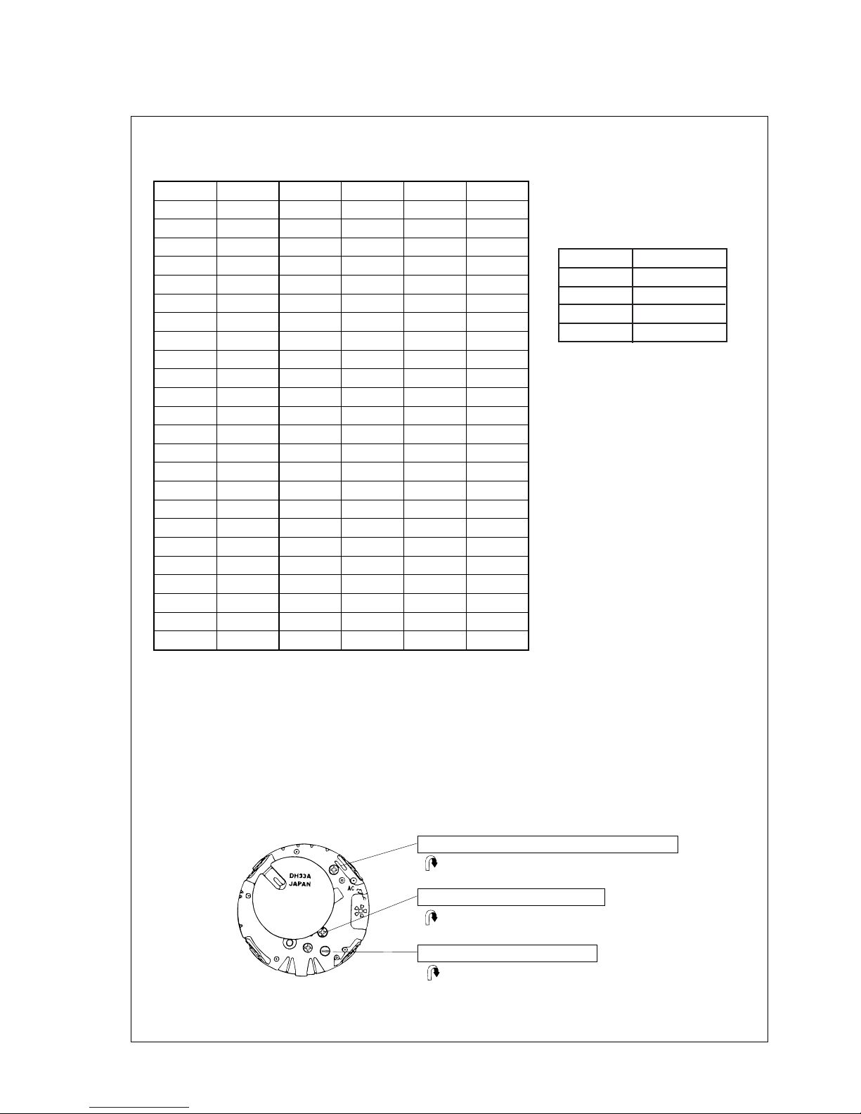
The table 1 below shows the pressure index value corresponding to the atmospheric pressure. The variance
in the pressure index value is within ± 1 count.
[ Table 1 ]
[ Table 2 ]
Altitude rank by pressure
index value
0
1
2
3
148
116
84
- 31
~
~
~
~
147
115
83
Altitude rank
A/D index value
209
208
207
206
205
204
203
202
201
200
199
198
197
196
195
194
193
192
191
190
189
188
187
186
1085
1083
1080
1078
1075
1073
1070
1068
1065
1063
1060
1058
1055
1053
1050
1048
1045
1043
1040
1038
1035
1033
1030
1028
185
184
183
182
181
180
179
178
177
176
175
174
173
172
171
170
169
168
167
166
165
164
163
162
1025
1023
1020
1018
1015
1013
1010
1008
1005
1003
1000
998
995
993
990
988
985
983
980
978
975
973
970
968
161
160
159
158
157
156
155
154
153
152
151
150
149
148
147
146
145
144
143
142
141
140
139
138
965
963
960
958
955
953
950
948
945
943
940
938
935
933
930
928
925
923
920
918
915
913
910
908
pressure index
value
pressure index
value
pressure index
value
atomospheric
pressure (hPa)
atomospheric
pressure (hPa)
atomospheric
pressure (hPa)
❖ Do not touch the adjustment screws unless any adjustment is requred.
Illustaration - The back of the module
Temperature adjustment screw
Pressure adjustment screw
Turn the screw clockwise (or counterclockwise) to adjust
temperature towards the minus (or plus) direction.
Turn the screw clockwise (or counterclockwise) to adjust
accuracy towards the loss (or gain) direction.
Turn the screw clockwise (or counterclockwise) to adjust
pressure towards the plus (or minus) direction.
Time Accuracy (loss/gain) adjustment screw
Page 8
8
TECHNICAL GUIDE
Cal. DH33A
● Time Accuracy
• In order to measure time accuracy, light up all the segments of the
display.
• Any gate of the quartz tester can be used for measurement.
<How to light up all the segments>
1. Press Button A several times to show the TIME/
CALENDAR mode.
2. Press Button B only once to change the display
to the TIME SETTING mode.
3. While in the TIME SETTING mode, press Button
C first, and while keeping it pressed, push Button
D in to light all the segments of the display.
4. To return to the normal display, press any button.
The watch will return to the TIME/CALENDAR
mode.
Button D
Button B Button C
Button A
 Loading...