

Page 1
表紙
Thank you for purchasing SEIKO SPORTS PRINTER CT-2000.
Before using your SEIKO SPORTS PRINTER, please read this
manual carefully for its proper use and care.
Keep this manual handy for ready reference.
Page 2
CAUTION
(1) This manual may not be copied or reproduced in any form, in whole or in part, without the
express written consent of SEIKO.
(2) This manual may be subject to change without prior notice.
(3) This manual has been prepared carefully to provide you with complete information for the
operation of this product. For the purpose of constant improvement in this manual, your
suggestions and comments on the descriptions included herein are highly appreciated.
(4) SEIKO shall not be liable for any failure of this product or direct or indirect damages resulting
from such failure if such failure is caused due to abuse or misuse of the product, failure to
observe instructions herein or neglect of other reasonable care, or servicing, changes,
modifications or alterations performed by other than SEIKO or a servicing contractor
authorized by SEIKO.
SAFETY ALERT SYMBOLS
The following symbols and terms used in this manual have the meaning as explained below. They
are intended to attract special attention of the users to the descriptions attached with them so that they
can use the product properly to prevent personal injuries and property damages. Before reading this
manual, be sure to understand what they mean.
W ARNING
This pictorial symbol with WARNING is used to indicate a potentially
hazardous situation which is likely to cause death or severe personal
injury if the instructions attached with them are not followed correctly.
CAUTION
This pictorial symbol with CAUTION is used to indicate a potentially
hazardous situation which is likely to cause personal injury or property
damage if the instructions under attached with them are not followed
correctly.
This pictorial symbol indicates what must NOT be done.
This pictorial symbol indicates what must be done.
Page 3

ー TABLE OF CONTENTS -
1. SAFETY PRECAUTIONS ............................................................................................................................................. 1
2. INTRODUCTION ............................................................................................................................................................... 3
2.1 Overview ........................................................................................................................... 3
2.2 Features ............................................................................................................................ 3
2.3 Lap Time and Split Time ................................................................................................... 4
2.4 System Components ........................................................................................................ 4
2.5 How to Open the Case ..................................................................................................... 5
2.6 Power Supply .................................................................................................................... 5
3. NAMES AND FUNCTIONS OF PARTS.......................................................................................................... 6
3.1 Battery Compartment ........................................................................................................ 6
3.1.1 How to Install the Batteries ..................................................................................................................................................................... 6
3.2 Connector Section ............................................................................................................ 7
3.3 Printer Section .................................................................................................................. 8
3.3.1 How to Install a Roll Paper ..................................................................................................................................................................... 9
3.3.2 How to Replace the Ribbon Cassette ........................................................................................................................................ 11
3.4 Monitor Section ............................................................................................................... 12
3.4.1 Memory ................................................................................................................................................................................................................. 12
3.4.2 Memory Block .................................................................................................................................................................................................. 13
3.4.3 Measurement Mode ................................................................................................................................................................................... 13
3.4.4 TIME UNIT ......................................................................................................................................................................................................... 14
3.4.5 BATT.1, BATT.2 (Remaining Power) ......................................................................................................................................... 14
3.5 Operation Section ........................................................................................................... 15
4. SETTING PROCEDURE ............................................................................................................................................ 17
4.1 Time/Calendar Setting .................................................................................................... 17
4.2 Dry Battery Setting .......................................................................................................... 18
4.3 Measurement Mode Setting ............................................................................................ 19
4.3.1 List of Setting Items Available for Each Measurement Mode ............................................................................... 20
4.4 How to Start Each Measurement Mode .......................................................................... 21
5. MEASUREMENT MODE ......................................................................................................................................... 22
5.1 Counting Mode (Measurement Mode No. 1)................................................................... 22
5.1.1 Features ............................................................................................................................................................................................................... 22
5.1.2 Operating Method ........................................................................................................................................................................................ 22
5.1.3 Example Printout .......................................................................................................................................................................................... 23
5.2 Parallel Counting Mode (Measurement Mode No. 2) ...................................................... 24
5.2.1 Features ............................................................................................................................................................................................................... 24
5.2.2 Operating Method ........................................................................................................................................................................................ 24
5.2.3 Example Printout .......................................................................................................................................................................................... 25
5.3 Parallel Lap/Split Time Measurement Mode (Measurement Mode No. 3) ...................... 26
5.3.1 Features ............................................................................................................................................................................................................... 26
5.3.2 Operating Method ........................................................................................................................................................................................ 26
5.3.3 Example Printout .......................................................................................................................................................................................... 27
5.4 Parallel Delayed Start Mode (Measurement Mode No. 4) .............................................. 28
5.4.1 Features ............................................................................................................................................................................................................... 28
5.4.2 Operating Method ........................................................................................................................................................................................ 28
5.4.3 Example Printout .......................................................................................................................................................................................... 29
Page 4

5.5 Time Correction Mode (Measurement Mode No. 5) ....................................................... 30
5.5.1 Features ............................................................................................................................................................................................................... 30
5.5.2 Operating Method (Master Unit) ..................................................................................................................................................... 30
5.5.3 Example Printout (Master Unit) ....................................................................................................................................................... 32
5.5.4 Operating Method (Secondary Unit) ........................................................................................................................................... 32
5.5.5 Example Printout (Secondary Unit) ............................................................................................................................................. 34
5.6 Auto Measurement-1 Mode (Measurement Mode No. 6) ............................................... 35
5.6.1 Features ............................................................................................................................................................................................................... 35
5.6.2 Operating Method ........................................................................................................................................................................................ 35
5.6.3 Example Printout .......................................................................................................................................................................................... 36
5.7 Auto Measurement-2 Mode (Measurement Mode NO. 7) ............................................... 37
5.7.1 Features ............................................................................................................................................................................................................... 37
5.7.2 Operating Method ........................................................................................................................................................................................ 37
5.7.3 Example Printout .......................................................................................................................................................................................... 38
5.8 Speed Measurement Mode (Measurement Mode No. 8) ................................................ 39
5.8.1 Features ............................................................................................................................................................................................................... 39
5.8.2 Operating Method ........................................................................................................................................................................................ 39
5.8.3 Example Printout .......................................................................................................................................................................................... 40
6. OTHER FUNCTIONS ................................................................................................................................................. 41
6.1 Start Time Setting ........................................................................................................... 41
6.1.1 Operating Method ........................................................................................................................................................................................ 41
6.2 Resetting Order of Arrival ............................................................................................... 42
6.2.1 Operating Method ........................................................................................................................................................................................ 42
6.2.2 Example Printout .......................................................................................................................................................................................... 42
6.3 Inputting Bib No. ............................................................................................................. 43
6.3.1 Operating Method ........................................................................................................................................................................................ 43
6.3.2 Example Printout .......................................................................................................................................................................................... 43
6.4 Memory Recall ................................................................................................................ 44
6.4.1 Operating Method ........................................................................................................................................................................................ 44
6.5 Reprinting Data in Memory ............................................................................................. 45
6.5.1 Operating Method ........................................................................................................................................................................................ 45
6.5.2 Example Printout .......................................................................................................................................................................................... 45
6.6 How to Clear Data in Memory ......................................................................................... 46
6.6.1 Operating Method ........................................................................................................................................................................................ 46
6.7 LOCK Switch .................................................................................................................. 47
6.8 SYNC (Synchronization) ................................................................................................. 48
6.8.1 Method of Synchronization via Start Signal .......................................................................................................................... 48
6.8.2 Method of Synchronization after Start ....................................................................................................................................... 48
6.9 PC DATA (Output of Data to Personal Computer) .......................................................... 50
6.9.1 Communication Specifications ......................................................................................................................................................... 50
6.9.2 Data format ........................................................................................................................................................................................................ 51
6.9.3 Data Format (Speed) ................................................................................................................................................................................ 52
7. TROUBLESHOOTING ............................................................................................................................................... 53
8. SPECIFICATIONS ......................................................................................................................................................... 54
Page 5
- 1 -
1. SAFETY PRECAUTIONS
The following precautions must be strictly observed for the safety of yourself and your fellow workers
and for the protection of property from loss and damages.
W ARNING
If the Product is giving out smoke or burnt smell, or showing
other abnormal symptoms, turn off the power switch and stop
using it. Then, checking that no more smoke is given out, call
your nearby SEIKO dealer or agent for repair service.
Unless you are a qualified electrician, never try to disassemble,
repair or modify the Product. Unauthorized disassembly, repair
or modification may cause an electric shock or fire.
Do not let any foreign matter such as pin and a piece of metal
enter into the inside of the Product. In case this has occurred,
turn off the power switch immediately, and stop using it. If the
Product is used continuously without being reconditioned, an
electric shock or fire may result. Call your nearby SEIKO dealer
or agent for repair.
Never operate the Product with wet hands. An electric shock or
malfunction may result.
Do not expose the Product to splashes of water. An electric
shock, malfunction or fire may result.
Never use any damaged power cord or plug, or loose socket.
An electric shock or fire may result.
Do not use or keep the Product at following places, as this may
cause an electric shock, malfunction or fire:
・Places under extremely high temperatures (such as those
exposed to direct sunlight);
・Dusty places;
・Places exposed to frequent vibrations; and
・Places subject to static electricity.
Page 6

- 2 -
CAUTION
Do not drop the Product, or hit it strongly against hard objects.
A malfunction or injury may result.
When connecting the Product with any accessory, optional or
other device, check that the connection is performed properly
and securely. A malfunction or failure may result.
Do not twist or pull strongly the cables to connect the Product
with the grip switch, or optional or other devices, or do not place
any heavy object on the cables. A malfunction of the Product or
break in them may result.
Install the dry batteries properly, checking that their (+) and (-)
terminals are properly aligned. A malfunction or failure may
result.
Do not use dry batteries of different types together. Otherwise,
heat generation or electrolyte leakage of the batteries may result
and cause damage to the Product.
Do not use old and new dry batteries together. Otherwise, heat
generation or electrolyte leakage of the batteries may result and
cause damage to the Product.
Use only dry batteries of the same make, type and size.
Otherwise, heat generation or electrolyte leakage of the
batteries may result and cause damage to the Product.
Use the dry batteries only within their specified operational
temperature range. The alkaline dry batteries, in particular,
should never be used in cold temperatures below the specified
range. Otherwise, they may not perform as specified, and a
malfunction of the Product may result.
If you decide not to use the Product for a long time, take out the
dry batteries. Otherwise, heat generation or electrolyte leakage
of the batteries may result and cause damage to the Product.
Please note that the AC cord (5m) enclosed with the AC adapter
can be used within Japan only.
When an external battery is used, use 11~14 V DC battery only.
A malfunction, fire or personal injury may result.
To feed the paper, be sure to operate the “FEED” button, and do
not pull the paper forcibly. This may damage the printer.
Do not turn off the switch while operating the Product.
Otherwise, the measurement data obtained so far will be
erased, and a malfunction or failure may result.
Do not expose the case of the Product to solvents such as
alcohol and gasoline, spray of cosmetics or the like, cleaners,
adhesives, or paints. They may discolor, deteriorate or
damage the case due to chemical change.
Page 7

- 3 -
2. INTRODUCTION
2.1 Overview
The SEIKO Sports Printer CT-2000 is a multi-purpose printer/timer that can be used for various
sports events requiring timing such as track and road running races, swimming, ski and skate.
2.2 Features
z Being equipped with various measurement modes, CT-2000 can be used for timing of all types
of sports events.
z Timing down to 1/1,000 of a second is possible.
The method of calculating the fraction of a second can be selected from 10 types including
rounding up, rounding down and rounding off, thus making it possible to comply with various
timing rules adopted in different sports events.
z A large-sized LCD monitor is used to make it easier to check various types of information
displayed on it. (20 characters x 4 lines)
z The design of the grip switch is renewed so that it better fits into your palm and provides easier
switch operation.
z By using resin case, high durability has been achieved.
z If the dry batteries are installed when CT-2000 is powered by AC adapter, the power source
can be quickly switched over to the batteries in case of failure of AC power supply, to ensure
constant operation. *1
z Two sets of dry batteries (6 AA size cells per set) can be installed in the main body, and the
power source is switched over automatically between them. By replacing the unused set of dry
batteries with new ones, CT-2000 can be powered by the dry batteries continuously for a long
time.*1
z Rechargeable batteries can be used in place of alkaline dry batteries.*1
z CT-2000 can also be powered by external battery (DC11V~DC14V)*1
z The Auto Measurement Mode enables the measurement during individual practices performed
alone.
・ Reaction time (start reaction time: time after the start signal until swimmer’s feet have left the
starting block), lap time, and split time can be measured during swimming practices.
・ Lap time and split time can be measured during practices of speed skating, track, and other
races.*2
・ By outputting a signal to an external buzzer device, CT-2000 can control the device to
generate a starting sound automatically.*2
z Even if the actual start time has differed from the scheduled time, the Time Correction Mode
(inputting time difference from start time) corrects the scheduled start time set in advance in the
secondary CT-2000 units, enabling them to synchronize with the master CT-2000 unit.
z The Speed Measurement Mode measures the average speed over a given section of the entire
distance.*2
z By connecting a Bib No. input device with CT-2000, the measured times can be printed out
together with the Bib No.*2
z CT-2000 can be connected with a personal computer via USB interface.
z Two types of time signals (RS-422) are output to the scoreboard (with or without running time
data).
z A synchronization signal can be output to external devices.
z As CT-2000 is compatible with CT-1000, the grip switches, extension unit, synchronization
cables, and cables to connect with scoreboard used previously with CT-1000 can also be used
with CT-2000 (with the exception of a cable used to connect with a personal computer).
*1: Dry batteries, rechargeable batteries and external battery are not included with CT-2000, and
they should be purchased separately if required.
*2: Optional device is required.
Page 8

- 4 -
2.3 Lap Time and Split Time
Lap time: Time required to go a given section of the
entire distance.
Split time: Time required to go from the start to any
given point of the entire distance.
2.4 System Components
① CT-2000 main body 1 unit
② GS-51 grip switch (with 2.5 m cable) 2 units
③ AC adapter (with 5 m cable) 1 unit
④ RP-03 roll paper 1 roll
⑤ ERC-22 ribbon cassette 1 unit (preset in printer section of main body)
⑥ Operating Manual (this document)
CT-2000 Main Body
GS-51 Grip Switch
AC Adapter
RP-03 Roll Paper
ERC-22 Ribbon Cassette
Page 9
- 5 -
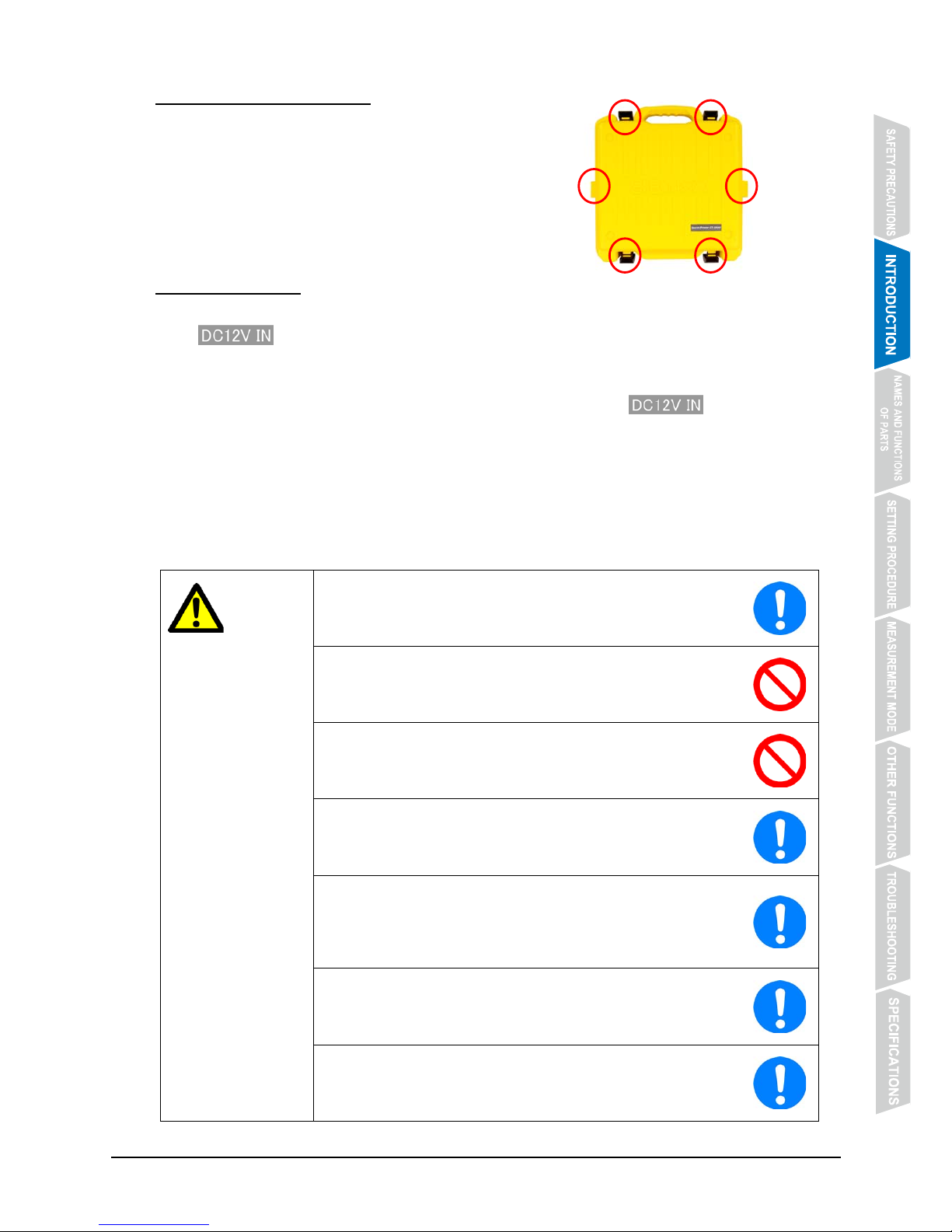
2.5 How to Open the Case
Place the case with the side attached with a sticker
facing toward you, and unlock the four locks on the
upper and lower sides and two locks on the side
faces to open the case.
2.6 Power Supply
z CT-2000 can be supplied with the power from two sources. One is the power source connected
to @@@@@ (AC adapter or external battery), and the other is either of the two sets of dry
batteries.
z For external battery, use 11~14 V DC battery only.
z Rechargeable batteries can be used in place of alkaline dry batteries.
z When all types of power sources are available, the one connected to @@@@@ will be used.
z When CT-2000 is powered by the dry batteries, the LED lamp above the battery compartment
of the batteries in use lights up.
z When replacing the dry batteries with new ones, be sure to replace those in the battery
compartment whose LED lamp stays out.
z When the battery power of both sets of dry batteries has reduced to a low level, both sets are
used at the same time.
In that case, the LEDs of both battery compartments light up. Replace the batteries with new
ones set by set.
CAUTION
Install the dry batteries properly, checking that their (+) and (-)
terminals are properly aligned. A malfunction or failure may
result.
Do not use dry batteries of different types together. Otherwise,
heat generation or electrolyte leakage of the batteries may result
and cause damage to the Product.
Do not use old and new dry batteries together. Otherwise, heat
generation or electrolyte leakage of the batteries may result and
cause damage to the Product.
Use only dry batteries of the same make, type and size.
Otherwise, heat generation or electrolyte leakage of the
batteries may result and cause damage to the Product.
Use the dry batteries only within their specified operational
temperature range. The alkaline dry batteries, in particular,
should never be used in cold temperatures below the specified
range. Otherwise, they may not perform as specified, and a
malfunction of the Product may result.
If you decide not to use the Product for a long time, take out the
dry batteries. Otherwise, heat generation or electrolyte leakage
of the batteries may result and cause damage to the Product.
When an external battery is used, use 11~14 V DC battery only.
A malfunction, fire or personal injury may result.
Page 10

- 6 -
3. NAMES AND FUNCTIONS OF PARTS
3.1 Battery Compartment
No. Name Function
①
BATT.1
Open the battery compartment cover, and install the batteries.
②
BATT.2
③
LED The LED of the compartment of the batteries in use lights up.
3.1.1 How to Install the Batteries
① Put your finger on the protrusion of the battery compartment cover, and pull it up to open the
cover.
② Install the dry batteries while checking that their (+) an (-) terminals are properly aligned.
① ②
③
③
Page 11
- 7 -
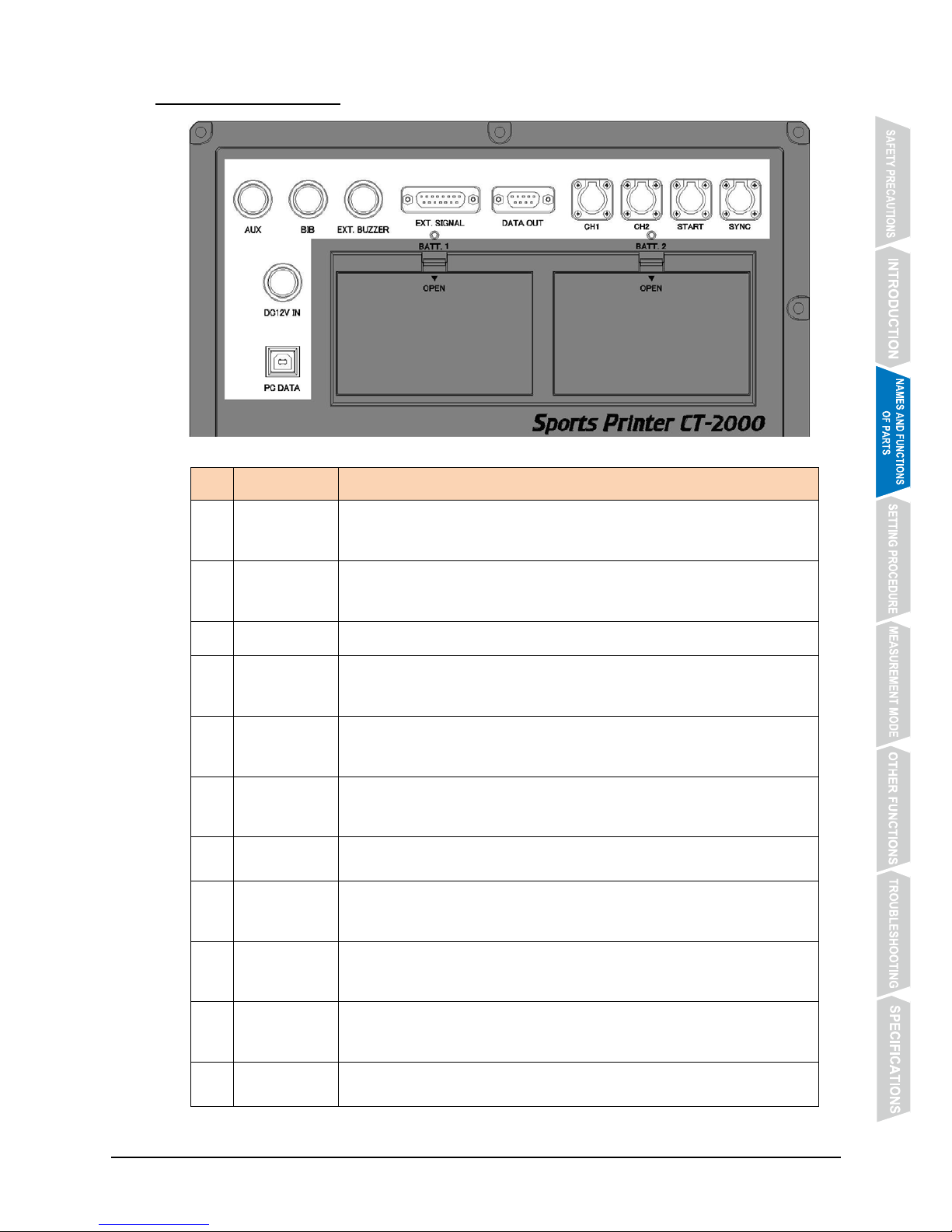
3.2 Connector Section
No. Name Function
①
PC DATA
Connect with a personal computer using a USB cable.
* For details, refer to【 6.9 PC DATA (Output of Data to Personal
Computer
)】on P. 50.
②
DC12V IN
Connect AC adapter included with CT-2000 or an external battery.
After connection, be sure to fix the cable securely in the same manner
as you would turn the screw.
③
AUX
It is an unused connector (for extending functionality).
④
BIB
Connect Bib No. input device.
After connection, be sure to fix the cable securely in the same manner
as you would turn the screw.
⑤
EXT.BUZZER
Connect external buzzer device.
After connection, be sure to fix the cable securely in the same manner
as you would turn the screw.
⑥
EXT.SIGNAL
Connect input extension unit.
The number of input channels can be increased to a maximum of 10.
After connection, be sure to fix the cable using the lock screw.
⑦
DATA OUT
Two types of time signals (RS-422) are output to the scoreboard.
After connection, be sure to fix the cable using the lock screw.
⑧
CH1
By connecting a grip switch, etc., CH1 signal can be input.
Mate the protrusions of the plug and receptacle connectors with each
other, and push in the plug until it clicks fixed.
⑨
CH2
By connecting a grip switch, etc., CH2 signal can be input.
Mate the protrusions of the plug and receptacle connectors with each
other, and push in the plug until it clicks fixed.
⑩
START
An external start signal can be input.
Mate the protrusions of the plug and receptacle connectors with each
other, and push in the plug until it clicks fixed.
⑪
SYNC
Use the connector to synchronize other units of CT-2000.
For details, refer to【6.8 SYNC (Synchronization)】on P. 48.
②
①
③
④
⑤
⑥ ⑦ ⑧ ⑨ ⑩ ⑪
Page 12
- 8 -
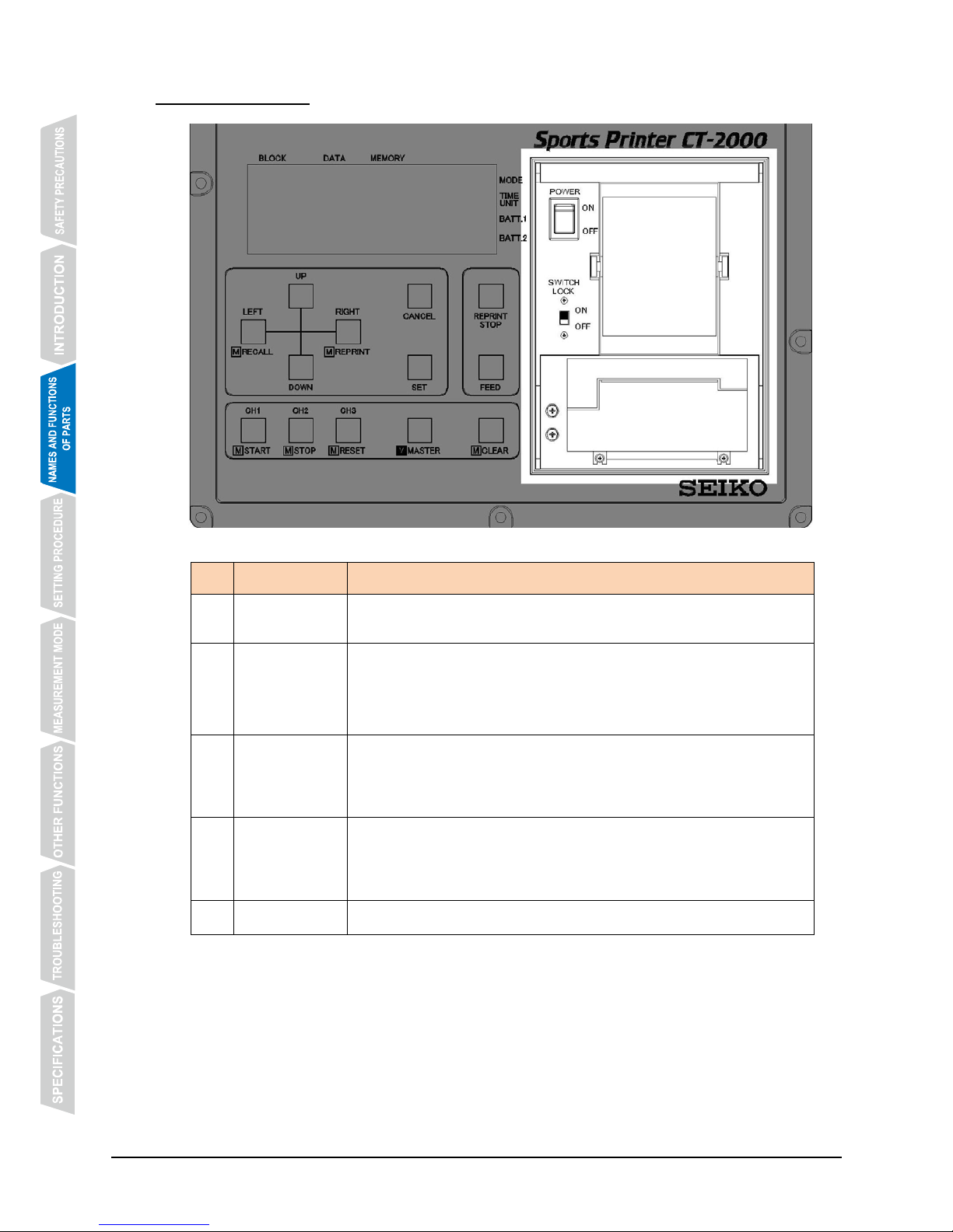
3.3 Printer Section
No. Name Function
①
POWER
switch
It turns on the power of CT-2000 main body.
②
LOCK switch
It prevents mistaken operation of the operation buttons.
By sliding it to “ON” position, all the buttons except “FEED” button are
disabled.
* For details, refer to【6.7 LOCK Switch】on P. 47.
③
Roll paper
It is a roll paper for use with the printer.
Be sure to use the one for exclusive use with CT-2000.
It is recommended that a new roll paper be installed when CT-2000 is
used for timing in a competition.
④
Ribbon
cassette
It is an ink ribbon cassette for use with the printer.
Be sure to use the one for exclusive use with CT-2000.
It is recommended that a new ribbon cassette be installed when
CT-2000 is used for timing in a competition.
⑤
Printer
It prints out the measurement data during and after measurement.
* The above parts are all located inside the printer cover.
①
②
③
④
⑤
Page 13

- 9 -
3.3.1 How to Install a Roll Paper
① Open the printer cover, turn on the POWER
switch, and take out the paper holder.
② Insert the edge of the paper into the paper inlet
of the printer.
③ Press @@@ to feed the paper until the edge
of the roll paper comes out from the outlet.
CAUTION
To feed the paper, be sure to operate the “FEED” button, and
do not pull the paper forcibly. This may damage the printer.
Page 14

- 10 -
④ Insert the paper holder into the roll paper.
⑤ Set the roll paper in position in the printer, and
close the printer cover.
Page 15
- 11 -
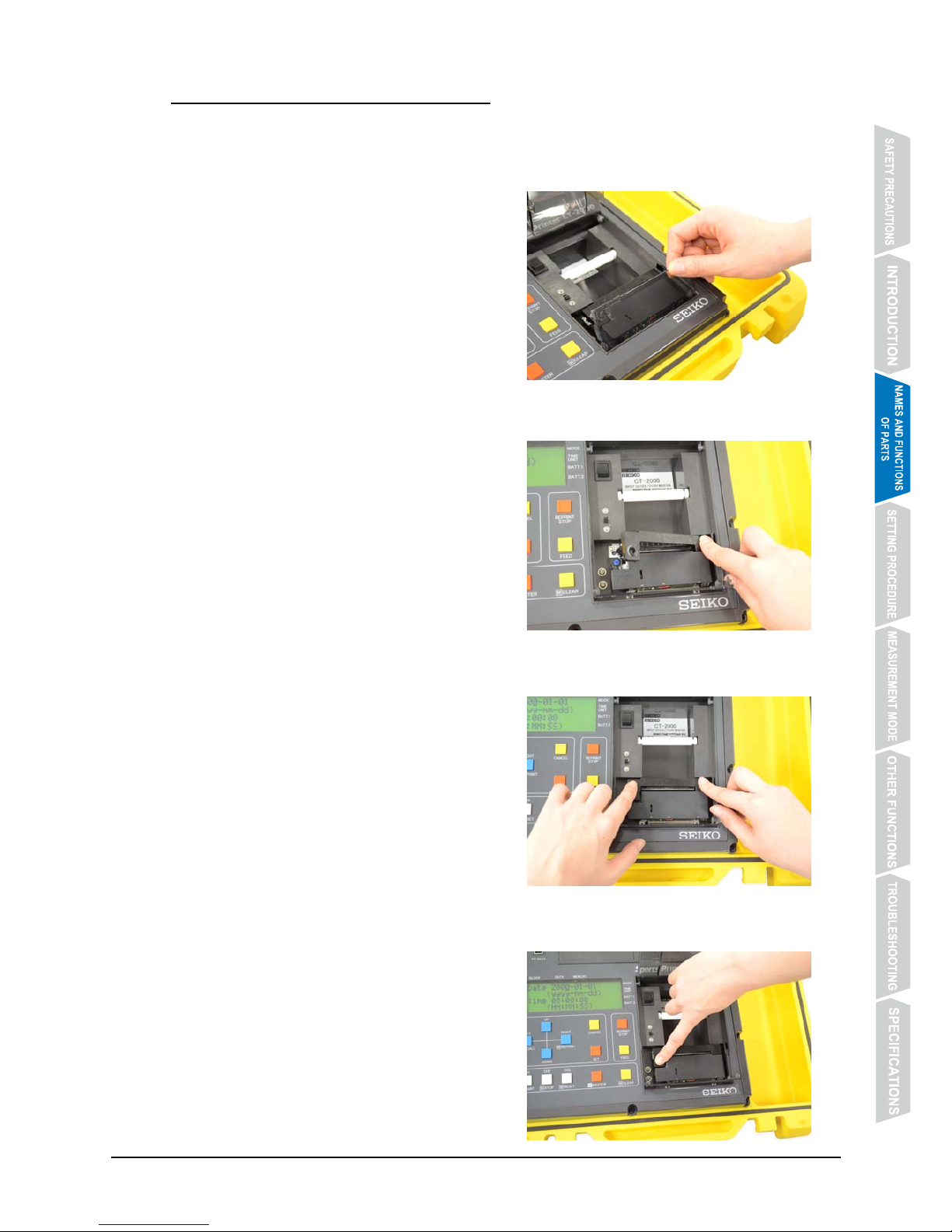
3.3.2 How to Replace the Ribbon Cassette
* When the roll paper has been installed inside the printer, take it out temporarily before
replacing the ribbon cassette.
① Open the printer cover and then ribbon
cassette cover.
② Push the “PUSH” portion of the ribbon cassette
to remove it.
③ Push in the new ribbon cassette until it clicks in
position.
④ Rotate the ribbon feed roller in the direction of
the arrow with a finger to remove the slack of
the ribbon.
Page 16

- 12 -
3.4 Monitor Section
No. Name Function
① BLOCK Block No. (up to 100) of the displayed memory block is indicated.
② DATA Data No. within the displayed block is indicated.
③ MEMORY
During measurement, the total number of data stored in memory is
indicated.
During recall, the number of data stored in the selected block is
indicated.
④ MODE Measurement Mode No. is indicated.
⑤ TIME UNIT The measurement unit is indicated.
⑥ BATT.1
Remaining power of each set of dry batteries is indicated.
⑦ BATT.2
3.4.1 Memory
z CT-2000 can store up to 3,000 measurement data in its memory.
z The measurement data is stored block by block, and up to 100 blocks can be stored.
z The data stored in memory can be recalled for display on the monitor section and for
reprinting by the printer as many times as necessary, before it is erased or the POWER
switch is turned off.
z When the number of data stored in memory reaches 3,000, new measurement will be printed
out but will not be stored in memory for later recall.
When the bib No. input device is connected to CT-2000, new measurement will be neither
printed out nor stored in memory.
* For the method of clearing data in memory, refer to【6.6 How to Clear Data in Memory】on P.
46.
①
②
③
④
⑤
⑥
⑦
Page 17

- 13 -
3.4.2 Memory Block
z The measurement data obtained from the start of the timer until it is stopped and reset is
stored in memory as one block of data.
z The block No. is assigned to each block automatically, and the data can be recalled and
reprinted by designating the corresponding block No.
z Up to 100 blocks can be stored in memory, and the block No. is assigned from “1” in the
order of measurement.
z When the block No. reaches 100, new measurement data will not be stored in memory.
z If the timer is started but no measurement is made until it is stopped and reset, no data is
stored in memory, and the block No. will not be incremented.
(Example)
Total number of
data in memory
1・・・100 101・・・ 300 301・・・500 ・・・
・・・3,000 (the last
data in memory)
Block No. 1 2 3
・・・
100 (the last block
in memory)
3.4.3 Measurement Mode
z Eight types of measurement modes are available.
z The number of the measurement mode currently in use is indicated on the monitor section.
Measurement
Mode No.
Measurement Mode
1 Counting Mode
2 Parallel Counting Mode
3 Parallel Lap/Split Time Measurement Mode
4 Parallel Delayed Start Mode
5 Time Correction Mode (inputting time difference from start time)
6 Auto Measurement-1 Mode
7 Auto Measurement-2 Mode
8 Speed Measurement Mode
* For details, refer to【5. MEASUREMENT MODE】on P. 22.
Page 18
- 14 -
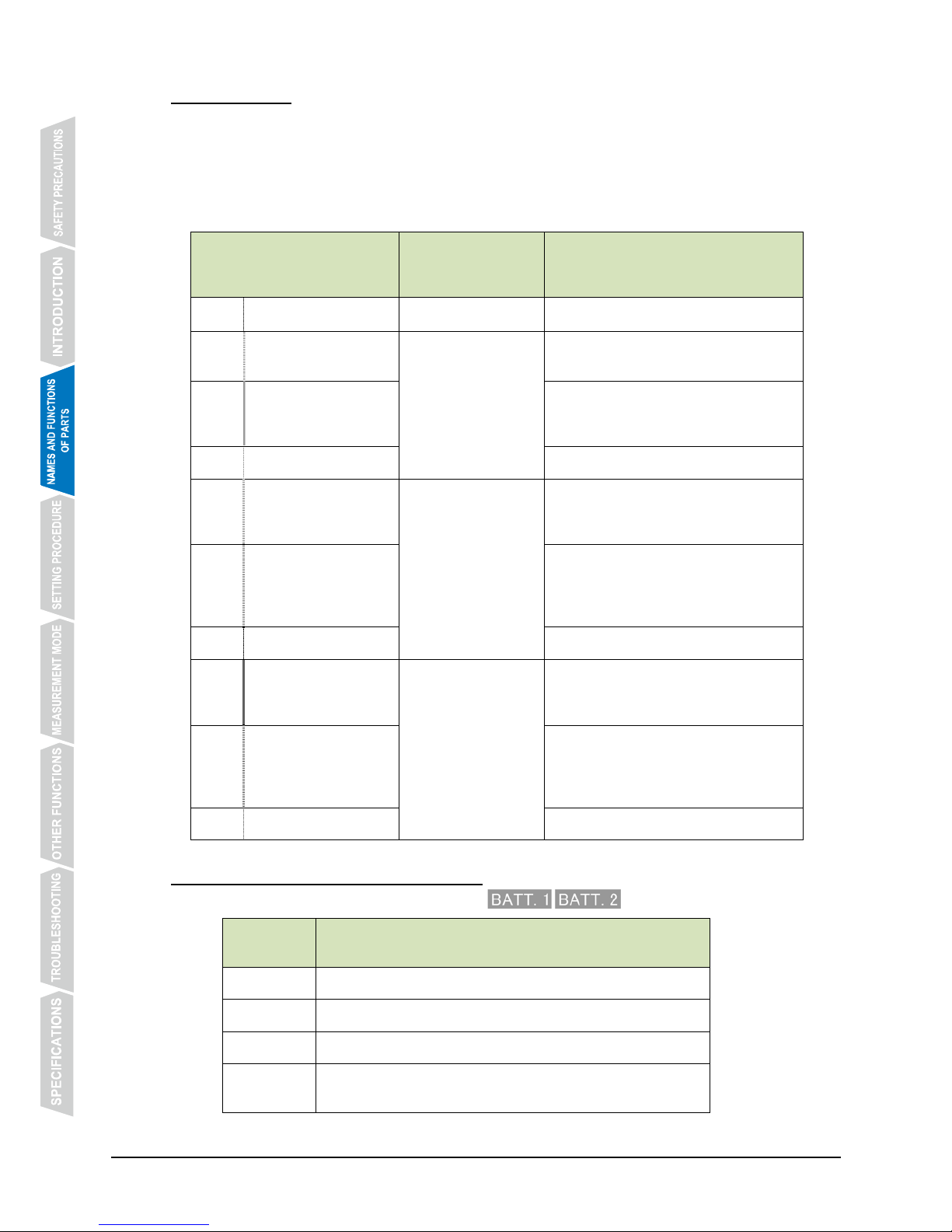
3.4.4 TIME UNIT
z 10 types of measurement increments are available.
z The time unit No. of the measurement unit currently in use is indicated on the monitor
section.
z The measurement data is stored in memory and printed out using the selected measurement
unit.
Time Unit No.
Measurement unit
of stored/printed
data
Method of calculating fraction of a
second
0 1/1000s 1/1,000 second
-
1 1/100s (discarding)
1/100 second
1/1000 sec. digit is discarded.
(1/1,000 sec. digit is rounded down.)
2 1/100s (raising)
1/1000 sec. digit is discarded, and
1/100 sec. digit is raised by one.
(1/1,000 sec. digit is rounded up.)
3 1/100s (rounding off) 1/1,000 sec. digit is rounded off.
4 1/10s (discarding)
1/10 second
1/100 sec. and lower digits are
discarded.
(1/100 sec. digit is rounded down.)
5 1/10s (raising)
1/100 sec. and lower digits are
discarded, and 1/10 sec. digit is
raised by one.
(1/100 sec. digit is rounded up.)
6 1/10s (rounding off) 1/100 sec. digit is rounded off.
7 1s (discarding)
1 second
1/10 sec. and lower digits are
discarded.
(1/10 sec. digit is rounded down.)
8 1s (raising)
1/10 sec. and lower digits are
discarded, and 1 sec. digit is raised
by one.
(1/10 sec. digit is rounded up.)
9 1s (rounding off) 1/10 sec. digit is rounded off.
3.4.5 BATT.1, BATT.2 (Remaining Power)
z The remaining power of the dry battery sets @@@@@@@@@@is indicated.
Indication
on monitor
Remaining Battery Power
H The batteries have sufficient power.
M The batteries near to their end.
L Replace the batteries with new ones.
x
The battery power has depleted completely, or no battery
is installed.
Page 19
- 15 -
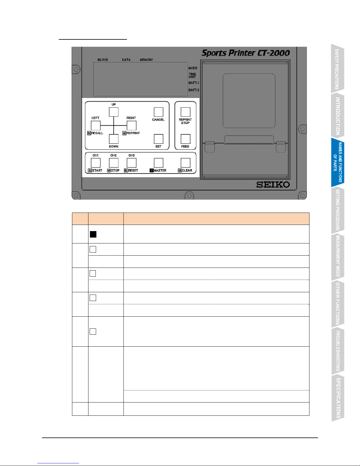
3.5 Operation Section
No. Name Function
①
M MASTER
Pressing it alone will not work.
It works when being pressed simultaneously with another button.
②
M START By pressing this button while keeping “MASTER” pressed, the timer starts.
CH1 Press this button alone to input CH1 signal.
③
M STOP By pressing this button while keeping “MASTER” pressed, the timer stops.
CH2 Press this button alone to input CH2 signal.
④
M RESET By pressing this button while keeping “MASTER” pressed, the timer is reset.
CH3 Press this button alone to input CH3 signal.
⑤
M CLEAR
By pressing this button while keeping “MASTER” pressed, the display to
clear data in memory appears.
* For details, refer to【6.6 How to Clear Data in Memory】on P. 46.
⑥
UP
By pressing this button while keeping “MASTER” pressed in the Time
Correction Mode, the time difference from the scheduled start time can be
input.
* For details, refer to【5.5 Time Correction Mode (Measurement Mode No.
5】on P. 30.
Use this button to set items. (Increasing or advancing the value)
⑦
DOWN
Use this button to set items. (Decreasing or moving back the value)
① ② ③ ④ ⑤
⑥
⑦
⑧ ⑨
⑩
⑪
⑫
⑬
Page 20
- 16 -
No. Name Function
⑧
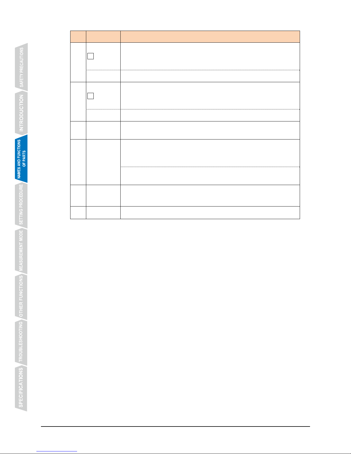
M RECALL
By pressing this button while keeping “MASTER” pressed, the mode
changes to “Recall”.
* For details, refer to【6.4 Memory Recall】on P. 44.
LEFT
When setting items, press this button to move the cursor to left.
⑨
M
REPRINT
By pressing this button while keeping “MASTER” pressed, the mode
changes to “Reprint”.
* For details, refer to【6.5 Reprinting Data in Memory】on P. 45.
RIGHT When setting items, press this button to move the cursor to right.
⑩
SET
When setting items, press this button to register the setting you have
made.
⑪
CANCEL
By pressing this button while keeping “MASTER” pressed, the display to
select measurement mode appears.
* For details, refer to【4. SETTING PROCEDURE】on P. 17.
When setting items, press this button to cancel the setting you have
made.
⑫
REPRINT
STOP
Press this button to stop printout while reprinting data.
* For details, refer to【6.5 Reprinting Data in Memory】on P. 45.
⑬
FEED
Press this button to fee the paper.
* By sliding LOCK switch to “ON” position, all the buttons except “FEED” are disabled.
For details, refer to【6.7 LOCK Switch】on P. 47.
Page 21
- 17 -
4. SETTING PROCEDURE
4.1 Time/Calendar Setting
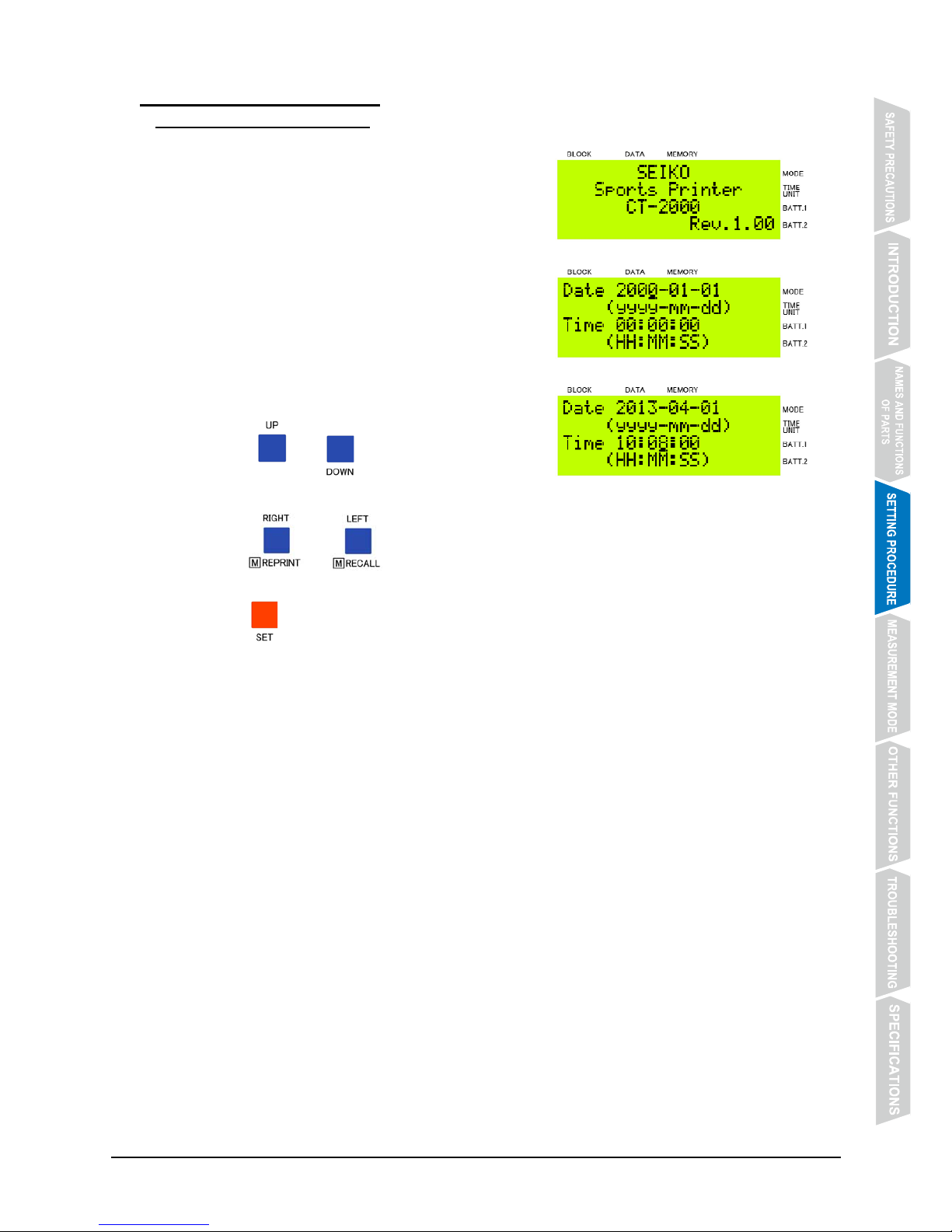
① Turn on “POWER” switch. The initial display appears.
② The time/calendar setting display is shown.
③ Set the year, month, date, hour, minute and second
digits.
Press @@@ or @@@ to set the time/calendar
digits.
Press @@@@ or @@@@ to move the cursor to the digits to be adjusted.
Press @@@ to register the setting you have made.
The registered time/calendar setting is retained inside CT-2000.
* When “POWER” switch is turned on, the time/calendar you registered previously is shown.
Set the time/calendar newly each time you turn on the power.
* To change the setting you have registered, be sure to turn off “POWER” switch, and then,
turn it on again to follow the procedure above.
Page 22
- 18 -
4.2 Dry Battery Setting
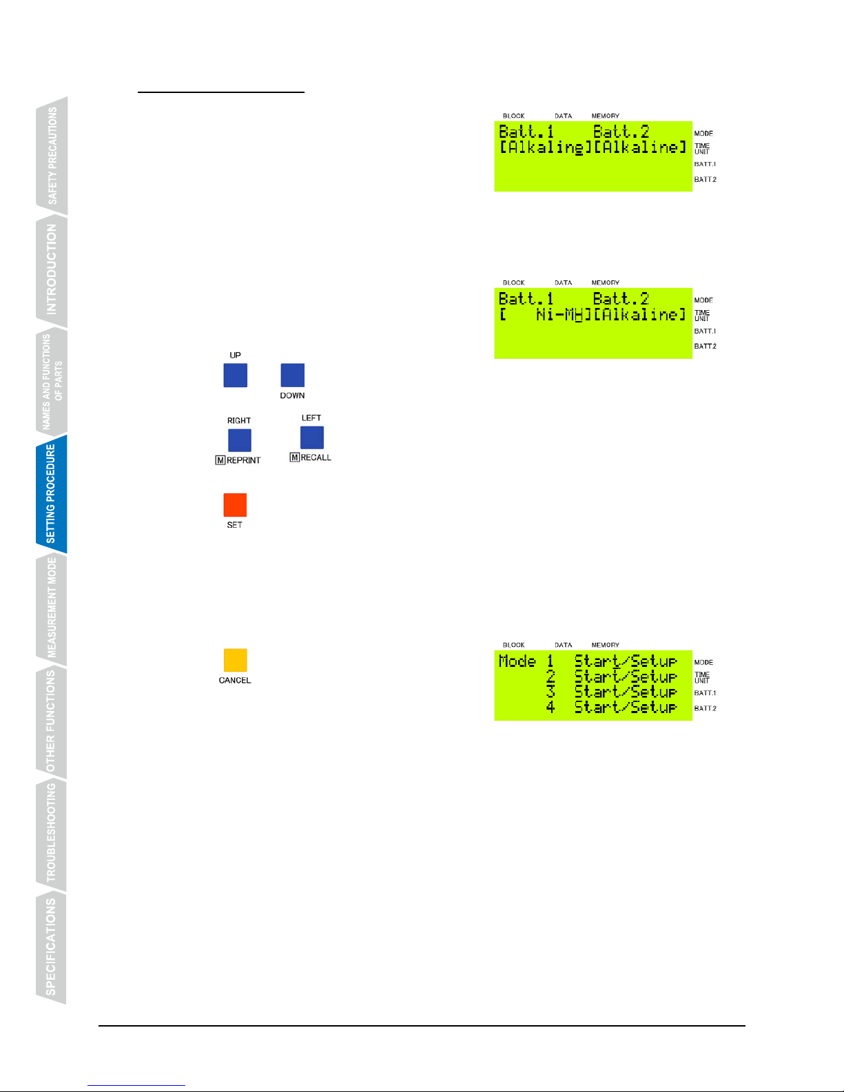
① The dry battery setting display is shown.
After the time/calendar is registered, the display
changes over to the dry battery setting display
automatically.
② Set the type of dry batteries to be used.
The battery type can be selected from alkaline dry
battery [Alkaline] and nickel-metal hydride
rechargeable battery [Ni-MH].
Press @@@ or @@@ to select the battery type.
Press @@@@ or @@@@ to move the cursor to select the battery type.
Press @@@ to register the setting you have made.
The registered dry battery setting is retained inside CT-2000.
* Even when only the AC adapter is used, be sure to make the dry battery setting above. In
that case, select [Alkaline] or [Ni-MH] as desired.
③ To change the dry battery setting:
Press @@@.while the measurement mode setting
display is shown. The dry battery setting display will
appear.
Page 23
- 19 -
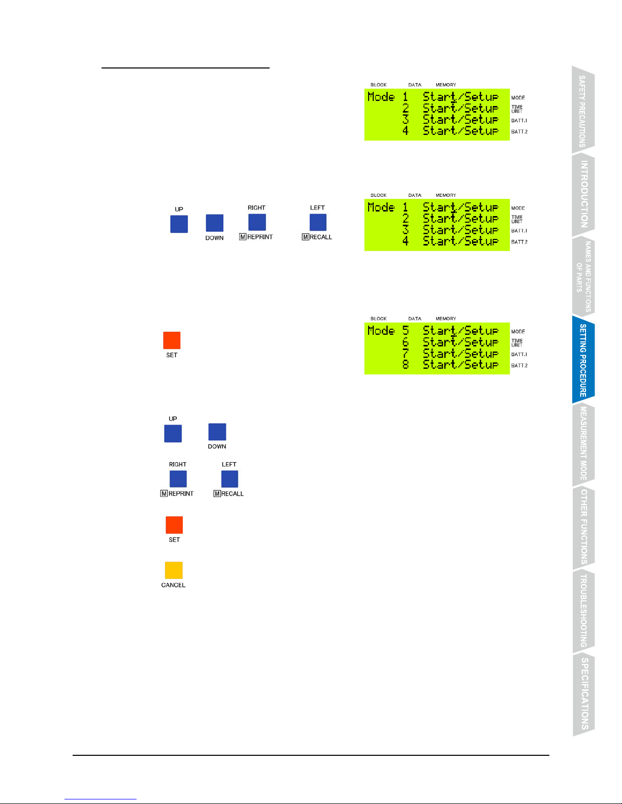
4.3 Measurement Mode Setting
① The measurement mode selection display is shown.
After the dry battery setting is registered, the
display changes over to the measurement mode
selection display automatically.
② Move the cursor to select the desired measurement mode.
Press @@@, @@@, @@@@ or @@@@ to
move the cursor to [Setup] of the measurement
mode you wish to use.
Press @@@ to register the setting you have made.
③ Set the items available for the selected measurement mode.
Press @@@ or @@@ to set the item.
Press @@@@ or @@@@ to move the cursor.
Press @@@ to register the setting you have made, and the next setting item appears.
Press @@@ to return to the previous setting item.
After the setting of all the available setting items is completed, the display returns to the
measurement mode selection display.
Page 24
- 20 -
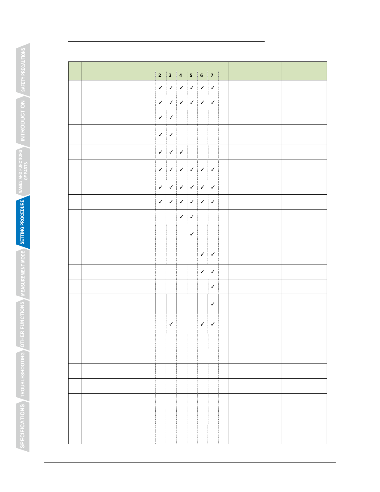
4.3.1 List of Setting Items Available for Each Measurement Mode
The setting items marked with “✓” are available for the respective measurement modes.
The registered settings are retained inside CT-2000.
No. Setting item
Measurement Mode No.
Setting value Remarks
1 2 3 4 5 6 7 8
1
Measurement unit
[Time Unit]
✓ ✓ ✓ ✓ ✓ ✓ ✓
0 ~ 9
Refer to P. 14.
2
Baud rate of data output
[Baud Rate]
✓ ✓ ✓ ✓ ✓ ✓ ✓
9600 bps / 19200 bps
3
Count up/down from set time
[Direction of Count]
✓ ✓ ✓
Up / Down
4
Auto countup after
countdown to “0”
[Auto Countup after 0]
✓ ✓ ✓
On / Off
Settable when
[Down] is selected
in No.3.
5
Interval of sync signal output
[Sync Signal Output]
✓ ✓ ✓ ✓
Per Minute / Per
Second
“Per Minute” is
built-in in No.5.
6
Buzzer when CH signal is
input
[CH Signal Beep]
✓ ✓ ✓ ✓ ✓ ✓ ✓ ✓
On / Off
7
Data output to printer
[Printing]
✓ ✓ ✓ ✓ ✓ ✓ ✓ ✓
Enable / Disable
8
Space between print lines
[Line Space]
✓ ✓ ✓ ✓ ✓ ✓ ✓ ✓
Normal / Wider
9
Use of bib No. input device
[Bib No. Input Device]
✓ ✓ ✓
On / Off
10
Display on scoreboard
during countdown
[Countdown Display]
✓
Enable / Disable
For master
CT-2000 only
11
Resting time of interval
training
[Interval Duration]
✓ ✓
0M10S ~ 59M59S
12
Use of starting cue
[Starting Cue]
✓ ✓
On / Off
13
The number of laps covered
[Number of Laps]
✓
1 ~ 99
14
Use of sound to signal final
lap
[Final Lap Signal]
✓
On / Off
15
Type of time data output to
scoreboard
[Display of Data]
✓ ✓ ✓
Split / Lap
Data displayed on
scoreboard
16
Speed measurement unit
[Speed Unit]
✓
km/h / mph / m/s
17
The number of PBUs set
[Number of PBUs]
✓
1 ~ 10
18
Distance between PBUs
[PBU-PBU Distance]
✓
1.0 ~ 100.0m
Set for each pair of
PBUs set in No.17.
19
Normal speed range (km/h)
[Normal Range of km/h]
✓
1 ~ 1000km/h
Effective if [km/h] is
selected in No.16.
20
Normal speed range (mph)
[Normal Range of mph]
✓
1 ~ 600mph
Effective if [mp h] is
selected in No.16.
21
Normal speed range (m/s)
[Normal Range of m/s]
✓
1 ~ 250m/s
Effective if [m/s] is
selected in No.16.
22
Use of measurement
timeout
[Measurement Timeout]
✓
On / Off
* When the normal speed range has been set, the printout has a marking if the measured speed is outside the specified
range.
Page 25
- 21 -
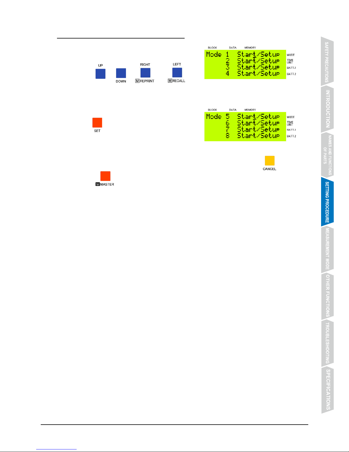
4.4 How to Start Each Measurement Mode
① Move the cursor in the measurement mode selection
display.
Press @@@, @@@, @@@@ or @@@@ to
move the cursor to [Start] of the measurement mode you wish to use.
Press @@@ to register the setting you have made.
② To change the measurement mode:
Check that the timer of each measurement mode is stopped, and press @@@ while
keeping @@@@ pressed. The measurement mode selection display will appear.
Page 26
- 22 -
5. MEASUREMENT MODE
5.1 Counting Mode (Measurement Mode No. 1)
5.1.1 Features
z This measurement mode is suitable for such sports events as track races, marathon, cycle
road races, and Nordic ski races.
z Order of arrival and split time are printed out each time a measurement is made from the
start to the finish.
z Order of arrival is printed out from 0001 to 9999, but the measurement can be continued
after the arrival of the 9,999th racer with the order of arrival being counted from 0000 (9999
→ 0000 → 0001 → 0002). When a bib No. input device is used, however, the order of arrival
is printed out up to 3000.
z Order of arrival is printed out from 0001 in order of signal input irrespective of the channel
through which the signal is input. It is possible, therefore, for one timekeeper to have two
grip switches, one in each hand, and input signals arbitrarily from either of them.
z By using an input extension unit, up to 10 CH signals can be input.*
z By using a bib No. input device, the measurement times and the corresponding bib No. can
be printed out together.*
z Running time (time elapsed from the start) and split time measured can be displayed on the
scoreboard (ST-306, etc.).*
* Input extension unit, bib No. input device and scoreboard are available as options.
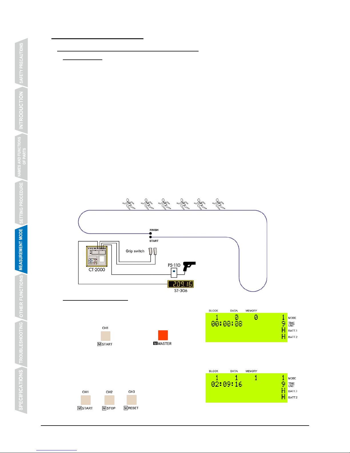
5.1.2 Operating Method
① Start the timer.
Input a start signal from an external device, or
press @@@@ while keeping @@@@ pressed
to start the timer.
② Measure the time.
Input a CH signal from a grip switch, or press
@@@, @@@ or @@@ to measure the time.
Page 27
- 23 -
③ Stop the timer.
Press @@@ while keeping @@@@ pressed to stop the timer.
Before the timer is reset, stop and reset of the timer can be repeated as many times as
necessary with the measurement data being stored in the same block No.
④ Reset the timer.
Press @@@ while keeping @@@@ pressed to stop the timer.
When the timer is reset, the display returns to the one shown in Step ① above, and the
block No. is incremented by one.
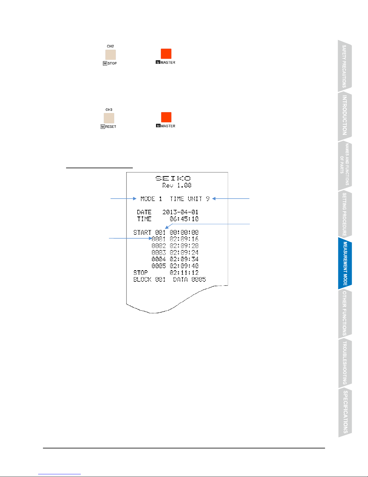
5.1.3 Example Printout
Measurement mode
Order of arrival
Block No.
Measurement unit
Page 28
- 24 -
5.2 Parallel Counting Mode (Measurement Mode No. 2)
5.2.1 Features
z This measurement mode is suitable for such sports events as track races, marathon,
swimming, cycle road races, speed skating, and boat and canoe races.
z Split time can be measured lane by lane (or racer by racer).
z Lane No. (that is, CH No.), number of laps, and split time are printed out.
z By using an input extension unit, up to 10 CH signals can be input.*
z Running time (time elapsed from the start) and split time measured can be displayed on the
scoreboard (ST-306, etc.).*
* Input extension unit and scoreboard are available as options.
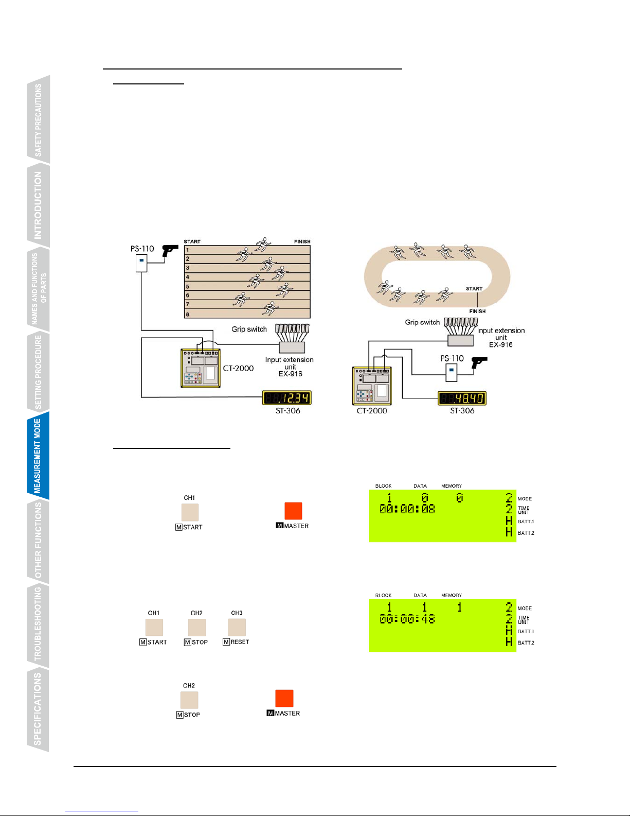
5.2.2 Operating Method
① Start the timer
Input a start signal from an external device, or
press @@@@ while keeping @@@@ pressed
to start the timer.
② Measure the time.
Input a CH signal from a grip switch, or press
@@@, @@@ or @@@ to measure the time.
③ Stop the timer.
Press @@@ while keeping @@@@ pressed to stop the timer.
Before the timer is reset, stop and reset of the timer can be repeated as many times as
necessary with the measurement data being stored in the same block No.
Page 29
- 25 -
④ Reset the timer.
Press @@@ while keeping @@@@ pressed to stop the timer.
When the timer is reset, the display returns to the one shown in Step ① above, and the
block No. is incremented by one.
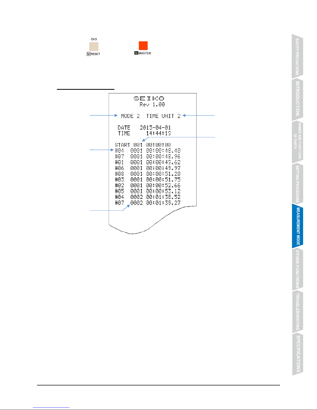
5.2.3 Example Printout
Measurement
mode
Input CH No.
by lane
Block No.
Number of laps
Measurement unit
Page 30
- 26 -
5.3 Parallel Lap/Split Time Measurement Mode (Measurement Mode No. 3)
5.3.1 Features
z This measurement mode is suitable for such sports events as track races, swimming, cycle
road races, speed skating and motor sports.
z Lap times and split times can be measured lane by lane (or racer by racer).
z Lane No. (that is, CH No.), number of laps, lap time and split time are printed out.
z By using an input extension unit, up to 10 CH signals can be input.*
z Running time (time elapsed from the start) and lap or split time measured can be displayed
on the scoreboard (ST-306, etc.).*
* Input extension unit and scoreboard are available as options
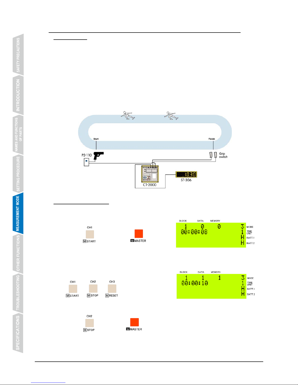
5.3.2 Operating Method
① Start the timer.
Input a start signal from an external device, or
press @@@@ while keeping @@@@ pressed
to start the timer.
② Measure the time.
Input a CH signal from a grip switch, or press
@@@, @@@ or @@@ to measure the time.
③ Stop the timer.
Press @@@ while keeping @@@@ pressed to stop the timer.
Before the timer is reset, stop and reset of the timer can be repeated as many times as
necessary with the measurement data being stored in the same block No.
Page 31
- 27 -
④ Reset the timer.
Press @@@ while keeping @@@@ pressed to stop the timer.
When the timer is reset, the display returns to the one shown in Step ①above, and the
block No. is incremented by one.
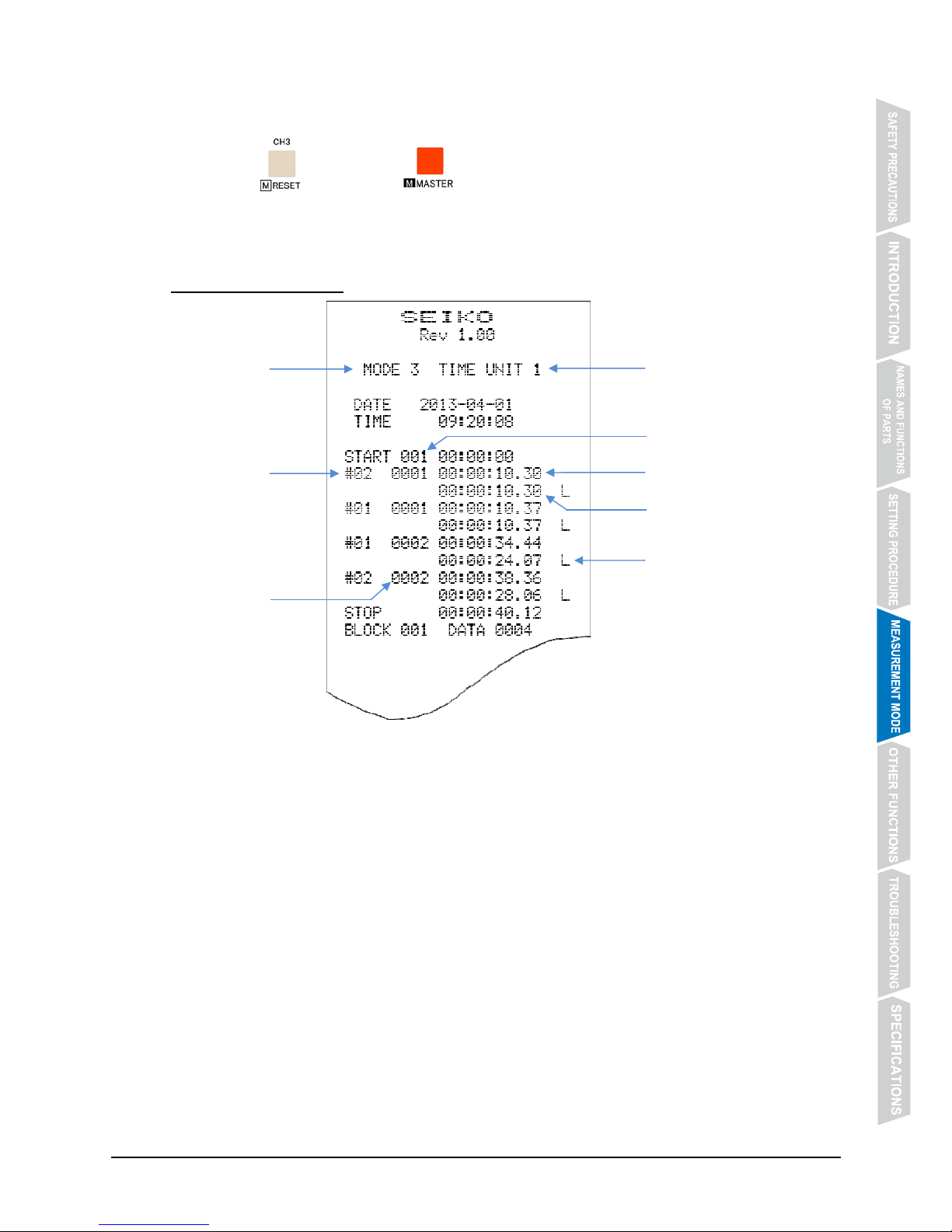
5.3.3 Example Printout
Measurement
mode
Input CH No.
by lane
Block No.
Lap time mark
Split time
Lap time
Number of laps
Measurement unit
Page 32
- 28 -
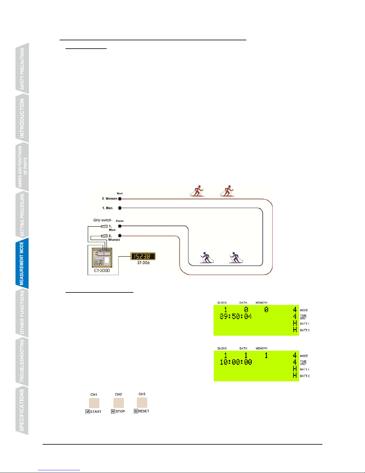
5.4 Parallel Delayed Start Mode (Measurement Mode No. 4)
5.4.1 Features
z This measurement mode is suitable for such sports events as marathon and Nordic ski
races.
z Time measurement of each racer can be made in a race where not all the racers start at the
same time but they start at different times at certain intervals.
z Different time measurements can be made according to the start times.
z The timer is started by inputting, at the start time, a CH signal corresponding to the group No.
(CH No.) .
The start time is recorded group by group (CH by CH). (No start signal is input.)
z Group No., finish time (current time at the finish line), order of arrival and split time are
printed out as classified by the start time.
z By using an input extension unit, up to 10 CH signals can be input.*
z By using a bib No. input device, the measurement times and the corresponding bib No. can
be printed out together.*
z Running time (time elapsed from the start) and split time measured can be displayed on the
scoreboard (ST-306, etc.).*
* Input extension unit, bib No. input device and scoreboard are available as options.
5.4.2 Operating Method
① The timer counts on the basis of the current time.
As the Parallel Delayed Start Mode is started, the
timer starts counting on the basis of the current
time.
② Input a CH signal that corresponds to the group No.
to start the measurement.
Input a CH signal from a grip switch
corresponding to the group No., or press
@@@@, @@@ or @@@ to start the measurement.
* Do not start the measurement by inputting an external start signal, or pressing [START]
while keeping [MASTER] pressed.
Page 33
- 29 -
③ Measure the time.
Input a CH signal from a grip switch, or press
@@@, @@@ or @@@ to measure the time.
④ Stop the timer.
Press @@@ while keeping @@@@ pressed to stop the timer.
⑤ Reset the timer.
Press @@@ while keeping @@@@ pressed to stop the timer.
When the timer is reset, the display returns to the one shown in Step ① above, and the
block No. is incremented by one.
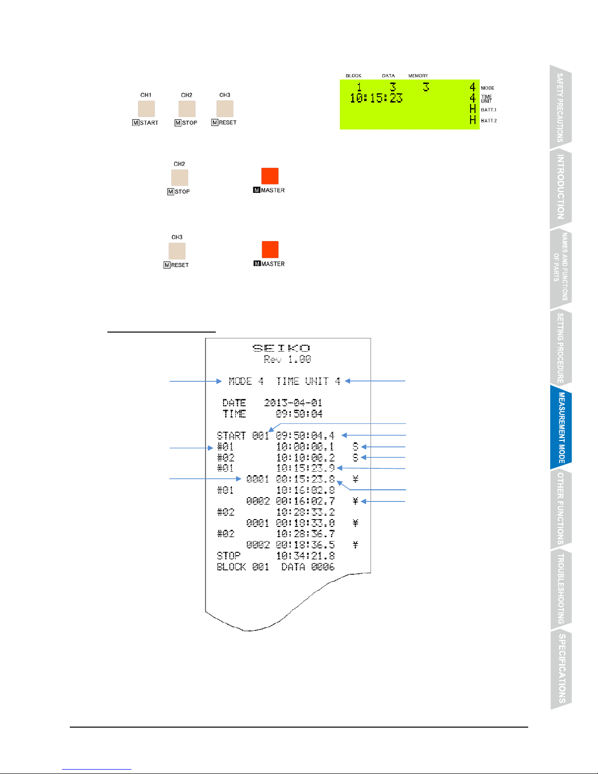
5.4.3 Example Printout
Time when timer is started
Start time of Men in Group 1
Measurement
mode
Group No.
(CH No.)
Block No.
Start time of Women in Group 2
Split time mark
Order of arrival
in each group
Finish time
Split time
Measurement unit
Page 34
- 30 -
5.5 Time Correction Mode (Measurement Mode No. 5)
5.5.1 Features
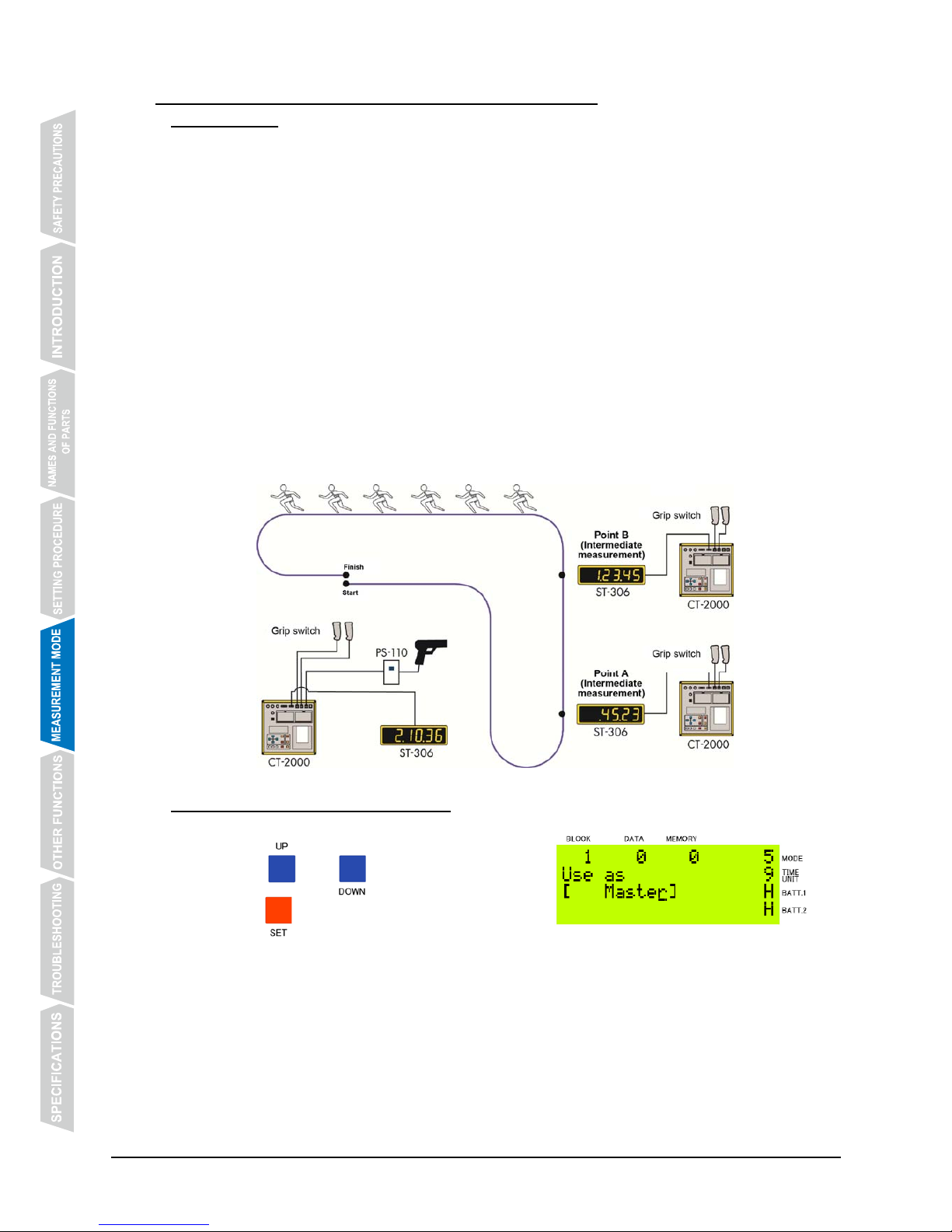
z This measurement mode is designed to measure the times at intermediate points on the
course in such sports events as marathon and Nordic ski races.
z The CT-2000 placed at the start point (Master) and the other units of CT-2000 placed at
some intermediate measurement points (Secondary) can be synchronized.
z Scheduled start time can be set in advance.
z It is possible to input the time difference between the scheduled and actual start times into
the Secondary units of CT-2000.
z Order of arrival and split time can be printed out.
z By using a bib No. input device, the measurement times and the corresponding bib No. can
be printed out together.*
z By using an input extension unit, up to 10 CH signals can be input.*
z Running time (time elapsed from the start) and split time measured can be displayed on the
scoreboard (ST-306, etc.).*
* Bib No. input device, input extension unit and scoreboard are available as options.
5.5.2 Operating Method (Master Unit)
① Designate the CT-2000 unit as Master.
Press @@@ or @@@ to select [Master], and
press @@@ to register the setting.
② Synchronize the Secondary CT-2000 units with the Master.
Connect the Secondary units with the Master using the sync cables, and synchronize the
Secondary units with the Master. After checking that synchronization has been achieved
disconnect the sync cables.
* The sync signal is output to all units of CT-2000 when the minute digits of the current
time is incremented irrespective of whether they are designated as [Master] or
[secondary].
Page 35
- 31 -
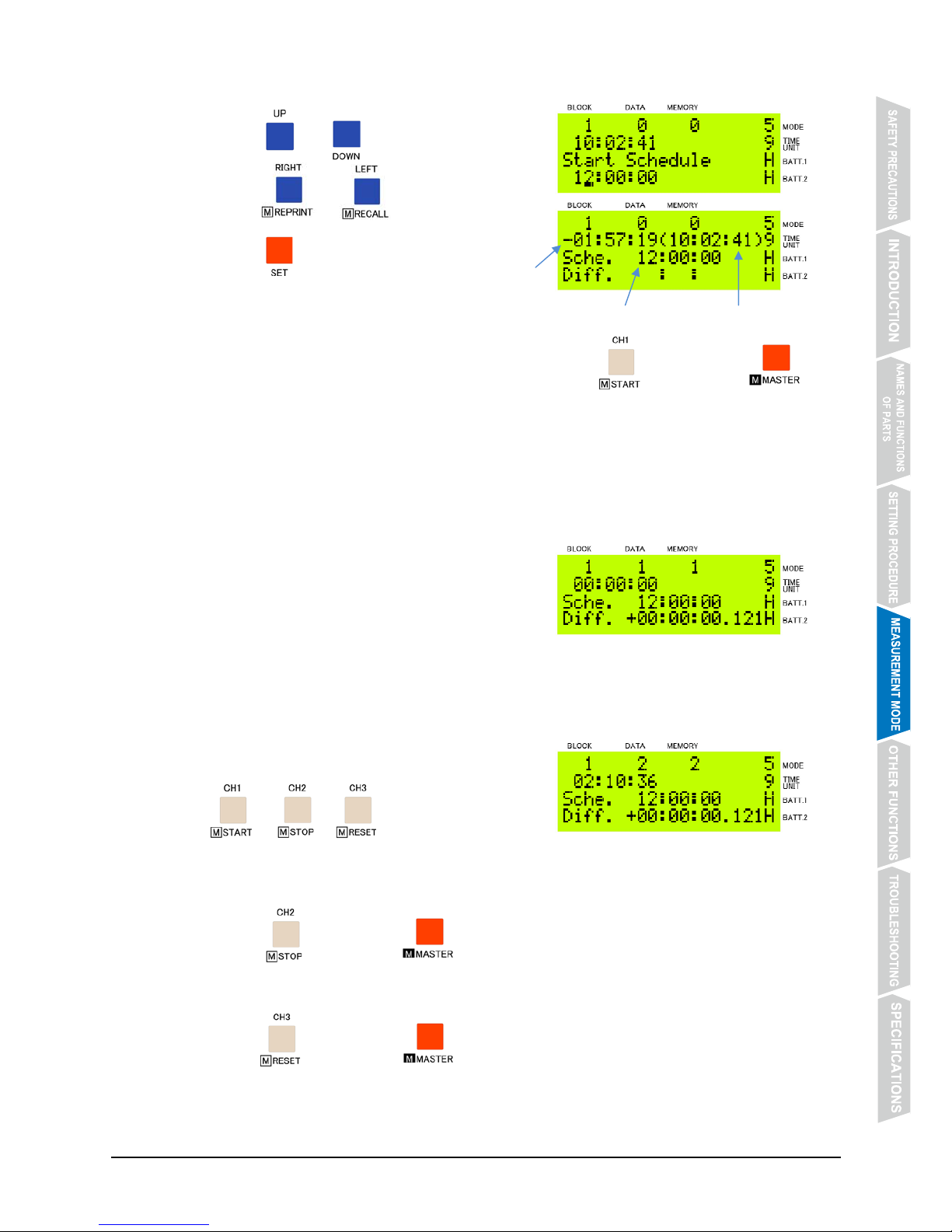
③ Set the scheduled start time.
Press @@@ or @@@ to set the time digits.
Press @@@@ or @@@@ to move the cursor.
Press @@@ to register the time you have set.
④ Input a start signal.
Input a start signal from an external device, or press @@@ while keeping @@@
pressed.
* Start signal can be input starting from 30 seconds before the scheduled start time.
If a start signal is input before that, [TEST] is printed out to indicate that the timer is
ready for the input of a start signal.
* By disabling [Countdown display], countdown of time before start will not be displayed
on the scoreboard.
For the setting procedure, refer to【4.3 Measurement Mode Setting】on P. 19.
⑤ The difference between the scheduled and actual
start times is calculated.
The difference between the time when the start
signal is input and the scheduled start time
(“Diff.”) is calculated and displayed.
* If the actual start time is earlier or later than the scheduled start time, “-” or “+” is
attached before the time difference, respectively.
⑥ Measure the time.
Input a CH signal from a grip switch, or press
@@@, @@@ or @@@ to measure the time.
* Time measurement cannot be made before the start signal has been input.
⑦ Stop the timer.
Press @@@ while keeping @@@@ pressed to stop the timer.
⑧ Reset the timer.
Press @@@ while keeping @@@@ pressed to stop the timer.
When the timer is reset, the display returns to the one shown in Step ① above, and the
block No. is incremented by one.
Scheduled start time Current time
Time before scheduled
start time
Page 36
- 32 -
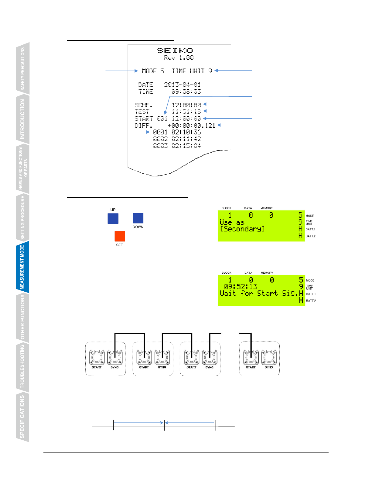
5.5.3 Example Printout (Master Unit)
5.5.4 Operating Method (Secondary Unit)
① Designate the CT-2000 unit as Secondary unit.
Press @@@ or @@@ to select [Secondary],
and press @@@ to register the setting.
② Synchronize Secondary units with Master. The
current time displayed will be corrected.
Connect the sync cables with [START]
connectors, and synchronize the Secondary units
with Master.
* Up to 10 Secondary units can be synchronized with each output of a sync signal.
A sync signal is output every minute from Master, and the time of Secondary unit that has
received it is corrected during a minute between the 30th second of a minute and the 29th
second of the next.
Measurement
mode
Block No.
Start signal input test
Time difference
Scheduled start time
Actual start time
・・・
Sync cable
9:52:30 9:53:00 9:53:29
Order of arrival
Measurement unit
Secondar
y
-
1 Secondar
y
-
2
Secondar
y
-
10
Master
Page 37
- 33 -
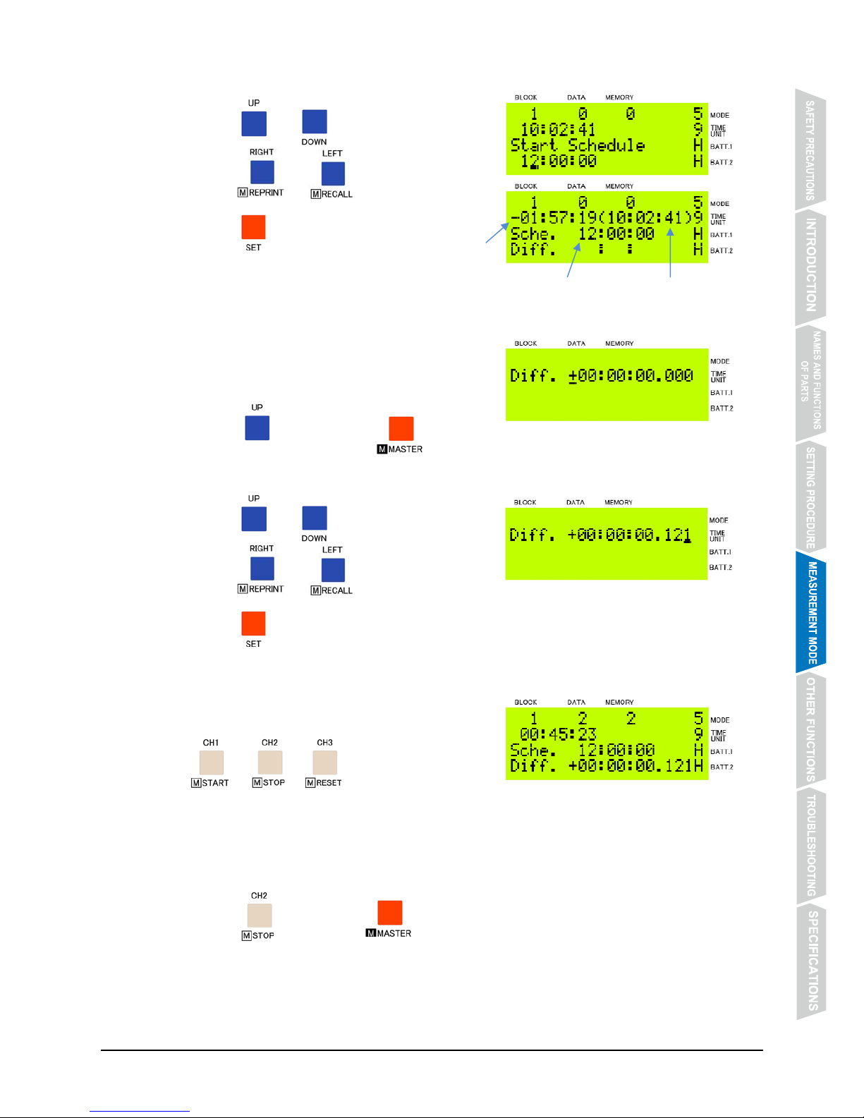
③ Set the scheduled start time.
Press @@@ or @@@ to set the time digits.
Press @@@@ or @@@@ to move the cursor.
Press @@@ to register the time you have set.
④ Input the difference between the scheduled and
actual start time.
Input the time difference (“Diff.”) calculated in
Master.
Press @@@ while keeping @@@@ pressed.
The display to input the time difference will appear.
Press @@@ or @@@ to set the time digits.
Press @@@@ or @@@@ to move the cursor.
Press @@@ to register the time difference you have set.
⑤ Measure the time.
Input a CH signal from a grip switch, or press
@@@, @@@ or @@@ to measure the time.
* Time measurement cannot be made before the scheduled start time.
⑥ Stop the timer.
Press @@@ while keeping @@@@ pressed to stop the timer.
Scheduled start time Current time
Time before scheduled
start time
Page 38
- 34 -
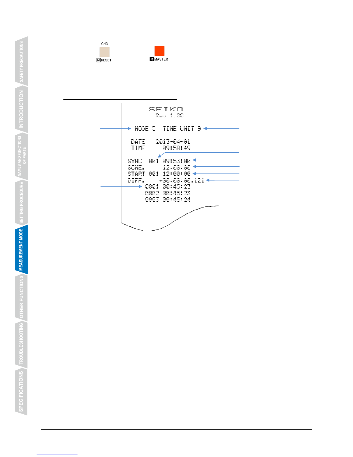
⑨ Reset the timer.
Press @@@ while keeping @@@@ pressed to stop the timer.
When the timer is reset, the display returns to the one shown in Step ① above, and the
block No. is incremented by one.
5.5.5 Example Printout (Secondary Unit)
Measurement
mode
Block No.
Scheduled start time
Time of synchronization
Actual start time
Order of arrival
Time difference
Measurement unit
Page 39
- 35 -
5.6 Auto Measurement-1 Mode (Measurement Mode No. 6)
5.6.1 Features
z This measurement mode is designed mainly for measurement in individual practice
performed alone.
z A start sound can be generated at a random interval after a starting cue corresponding to
“Take your marks.” *
z New measurement starts automatically after the interval time you have set has elapsed.
z The interval between the previous and new measurements (start interval) can be set within
the range from 10 seconds up to 59 minutes and 59 seconds.
z Reaction time (time after the start sound until swimmer’s feet have left the starting block), lap
time, split time are measured and printed out.*
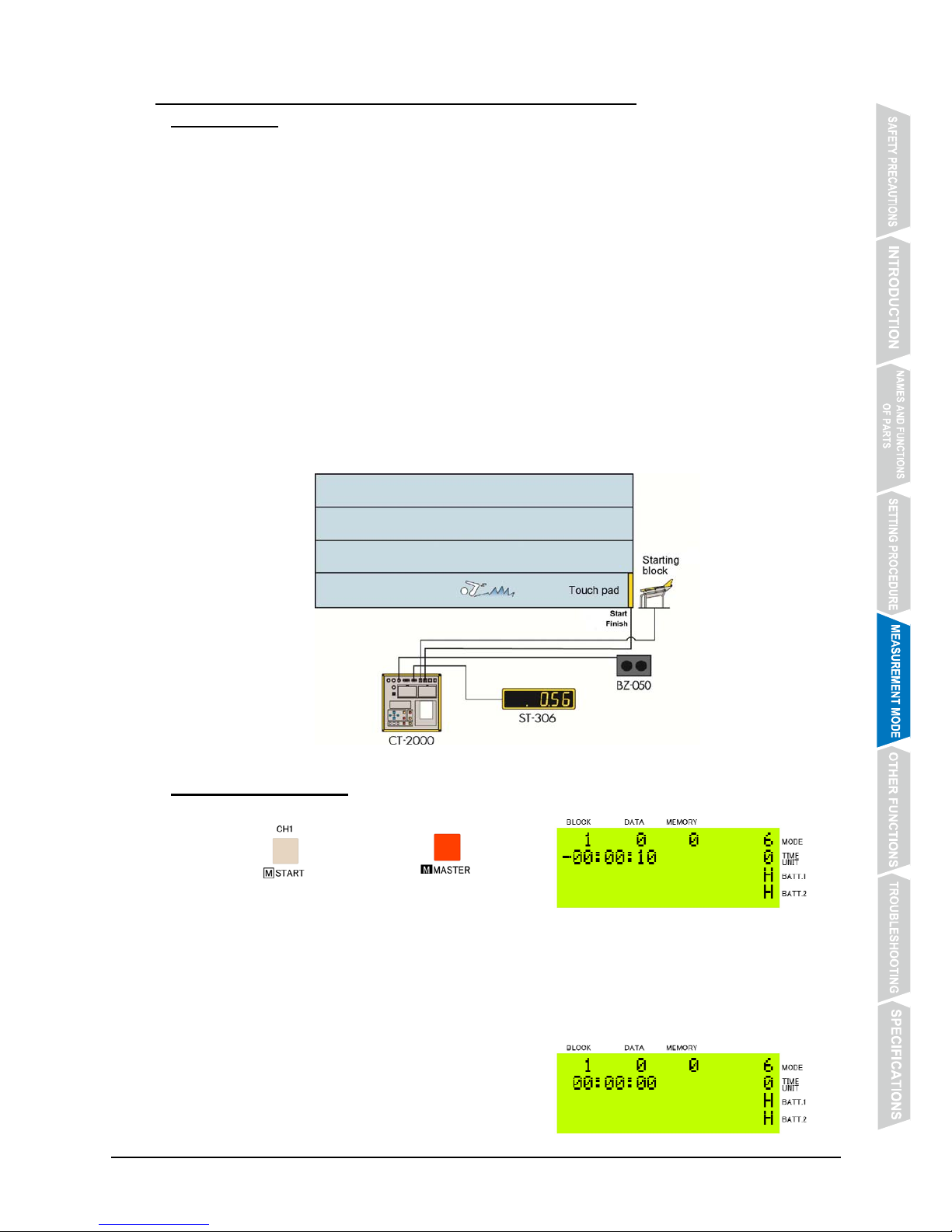
z Connect the starting block measuring reaction time with CH1, and the touch pad measuring
lap and split times with CH2.*
z Reaction time, and lap or split time can be displayed on the scoreboard (ST-306, etc.).*
* Optional devices are required.
5.6.2 Operating Method
① Start Auto Measurement-1 Mode.
Press @@@@ while keeping @@@@ pressed.
Auto Measurement-1 Mode starts.
② The starting cue sounds automatically.
The starting cue sounds approximately 10 seconds after the Mode starts.
* If the starting cue is turned off, it will not sound even if the Mode is started.
For the setting procedure, refer to【4.3 Measurement Mode Setting】on P. 19.
③ The start sound is generated automatically.
The start sound is generated at a random interval
of 3±1 seconds after the starting cue, and the
timer starts automatically.
Page 40
- 36 -
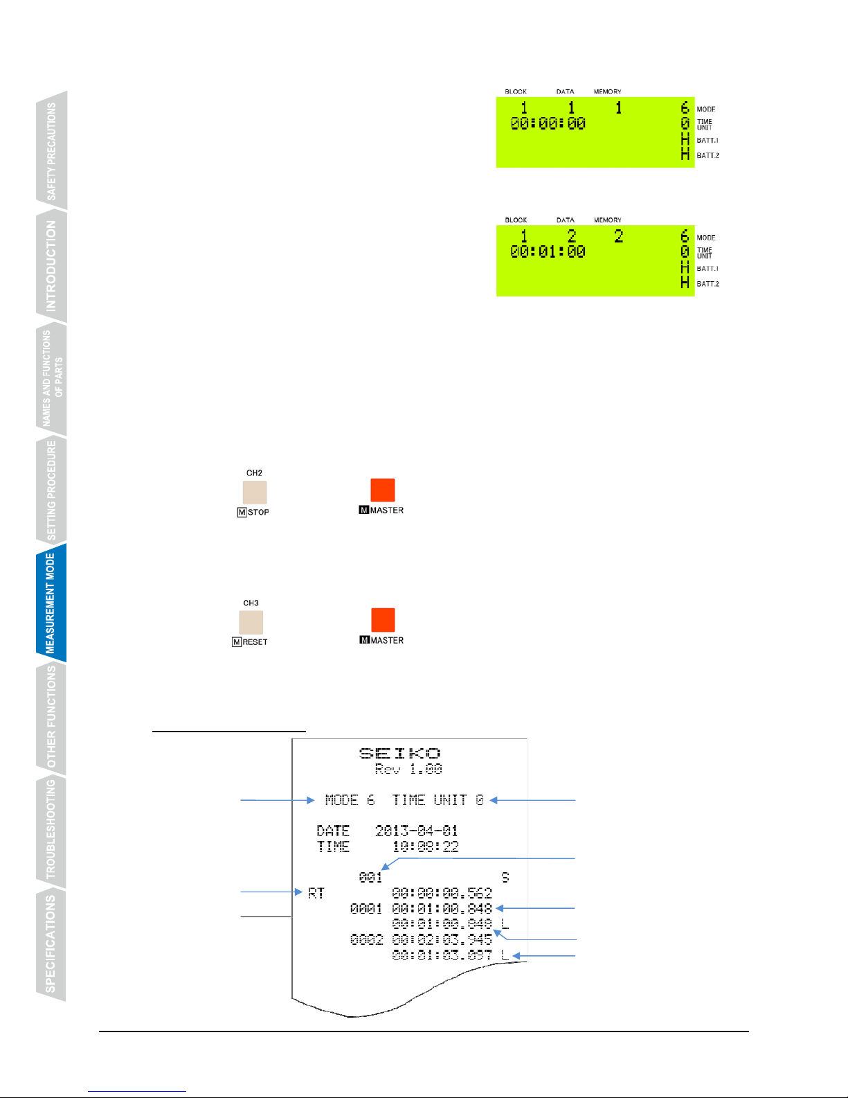
④ Reaction time is calculated.
The time elapsed after the start sound until
swimmer’s feet have left the starting block
connected to CH1 is calculated.
* For 5 seconds after the reaction time is
measured, lap/split time measurement cannot be made.
⑤ Lap/split times are measured.
The touch pad connected with CH2 measures
lap/split times.
* For 5 seconds after a lap/split time is measured,
new lap/split time measurement cannot be made.
⑥ New measurement starts automatically.
New measurement starts automatically after the interval time you have set has elapsed.
* For the setting procedure, refer to【4.3 Measurement Mode Setting】on P. 19.
* New measurement starts while the previous time measurement is in progress or the
touch pad did not measure any lap/split time.
⑦ Stop the timer.
Press @@@ while keeping @@@@ pressed to stop the timer.
Before the timer is reset, stop and reset of the timer can be repeated as many times as
necessary with the measurement data being stored in the same block No.
⑧ Reset the timer:
Press @@@ while keeping @@@@ pressed to stop the timer.
When the timer is reset, the display returns to the one shown in Step ① above, and the
block No. is incremented by one.
5.6.3 Example Printout
Measurement
mode
Reaction time
mark
Block No.
Lap time mark
Split time
Lap time
Measurement unit
Page 41
- 37 -
5.7 Auto Measurement-2 Mode (Measurement Mode NO. 7)
5.7.1 Features
z This measurement mode is designed for measurement in individual practice of sports events
that require lap/split time measurement.
z A start sound can be generated at a random interval after a starting cue corresponding to
“Take your marks.” *
z New measurement starts automatically after the interval time you have set has elapsed.
z The interval between the previous and new measurements (start interval) can be set within
the range from 10 seconds up to 59 minutes and 59 seconds.
z Lap time and split time are measured and printed out lap by lap.
z The number of laps can be set within the range from 1 to 99.
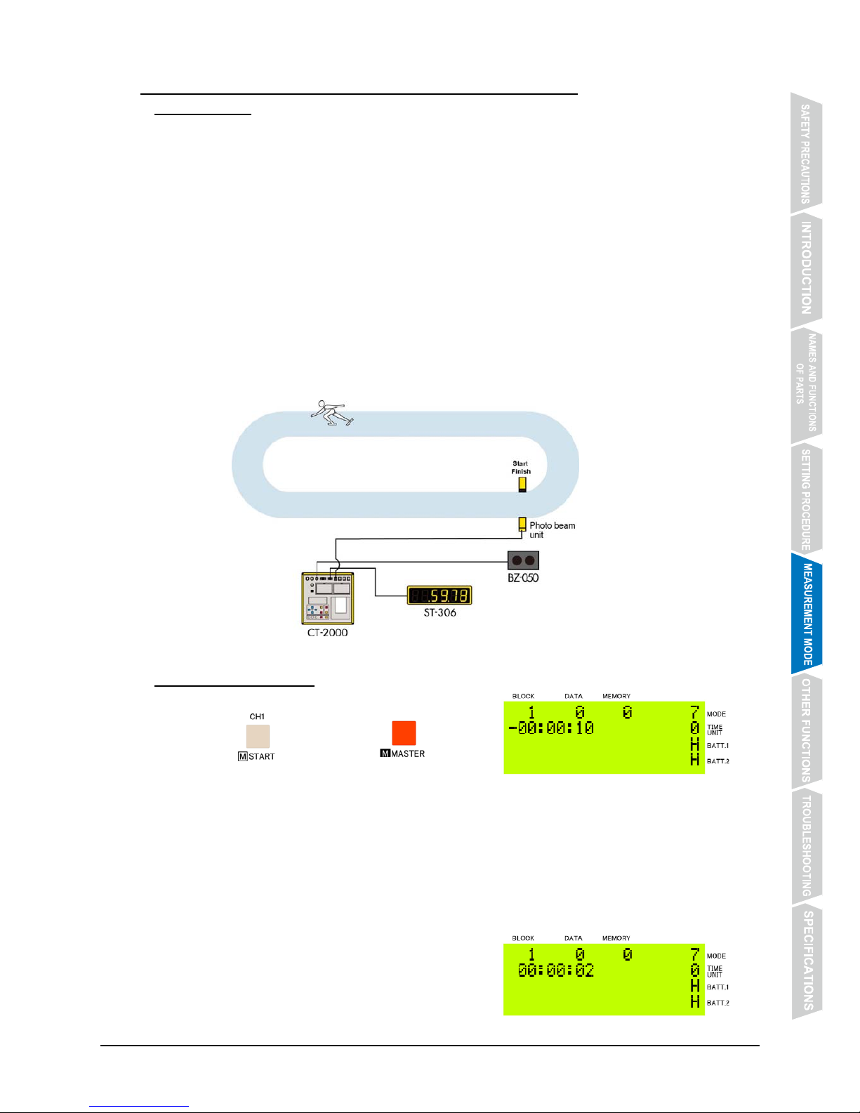
z Connect the photo beam unit to measure time with CH1.*
z Lap or split time can be displayed on the scoreboard (ST-306, etc.).*
* Optional devices are required.
5.7.2 Operating Method
① Start Auto Measurement-2 Mode.
Press @@@@ while keeping @@@@ pressed.
Auto Measurement-2 Mode starts.
② The starting cue sounds automatically.
The starting cue sounds approximately 10 seconds after the Mode starts.
* If the starting cue is turned off, it will not sound even if the Mode is started.
For the setting procedure, refer to【4.3 Measurement Mode Setting】on P. 19.
③ The start sound is generated automatically.
The start sound is generated at a random interval
of 3±1 seconds after the starting cue, and the
timer starts automatically.
Page 42
- 38 -
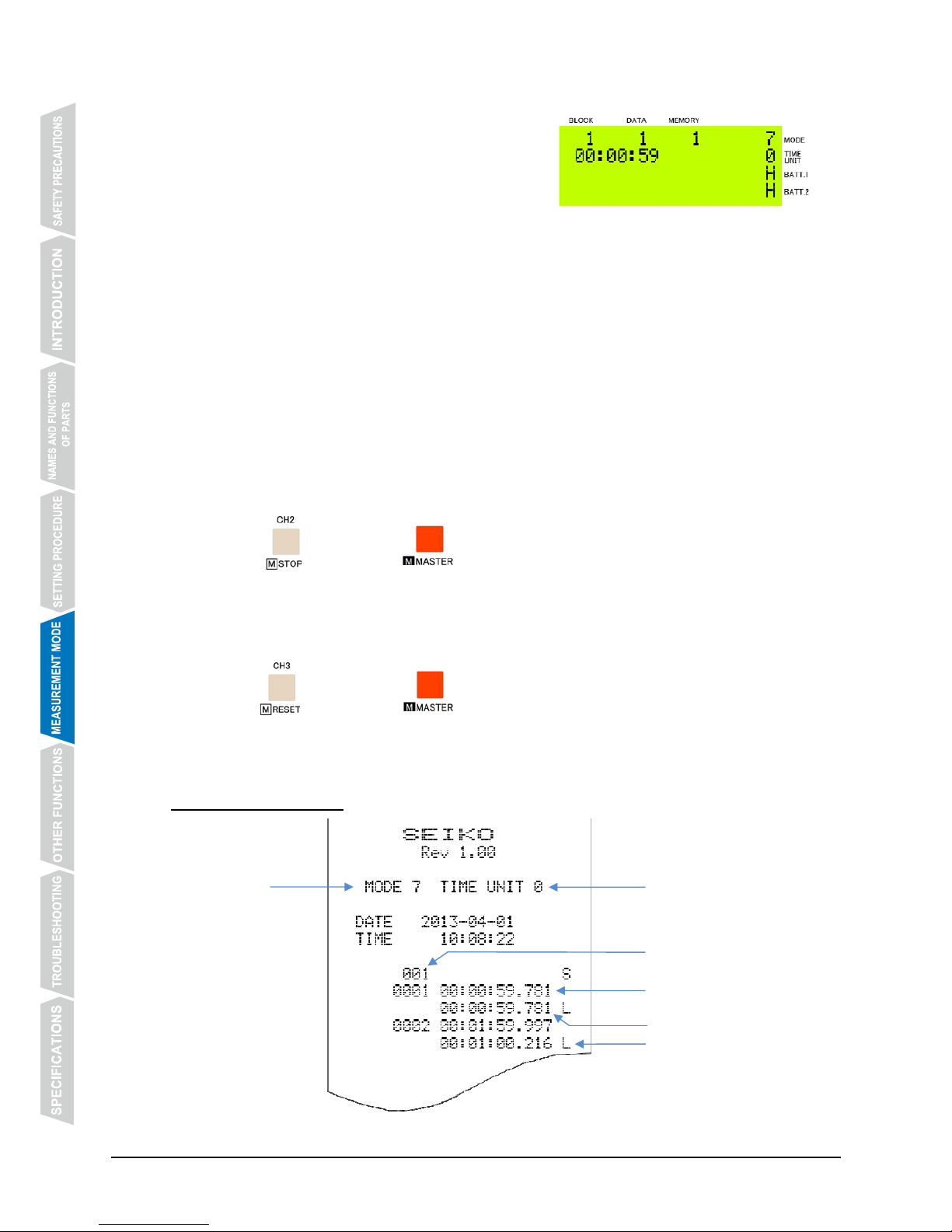
④ Lap/split times are measured.
The photo beam unit connected with CH1
measures lap/split times.
* For 5 seconds after the timer starts counting
and after a lap/split time is measured, new
lap/split time measurement cannot be made.
⑤ A sound to signal the final lap rings.
When the final lap starts, a sound to signal the final lap is generated.
* If the final lap signal is turned off, the sound will not be generated.
For the setting procedure, refer to【4.3 Measurement Mode Setting】on P. 19.
⑥ New measurement starts automatically.
New measurement starts automatically after the interval time you have set has elapsed.
* For the setting procedure, refer to【4.3 Measurement Mode Setting】on P. 19.
* New measurement starts while the previous time measurement is in progress or the
touch pad did not measure any lap/split time.
⑦ Stop the timer.
Press @@@ while keeping @@@@ pressed to stop the timer.
Before the timer is reset, stop and reset of the timer can be repeated as many times as
necessary with the measurement data being stored in the same block No.
⑧ Reset the timer:
Press @@@ while keeping @@@@ pressed to stop the timer.
When the timer is reset, the display returns to the one shown in Step ① above, and the
block No. is incremented by one.
5.7.3 Example Printout
Measurement
mode
Block No.
Lap time mark
Split time
Lap time
Measurement unit
Page 43
- 39 -
5.8 Speed Measurement Mode (Measurement Mode No. 8)
5.8.1 Features
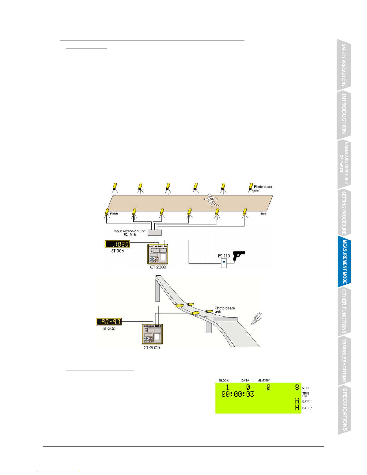
z The average speed in a given section of the entire distance is measured.
z The distance of the measurement section can be set from 1 m to 100 m in 10-cm increments.
z Up to 10 measurement sections can be set. Connect the photo beam units placed toward the
finish point with the connectors in order of [START], [CH1], [CH2] - - - [CH10].*
z The measurement unit of speed can be selected from km/h, m/s and mph (miles per hour).
z If there is no input CH signals during 3 seconds after a start signal, can be set to timeout
measurement.
z The speed measured is printed out.
z The normal speed range can be set. If the speed below the lower limit ([min]) or above the
upper limit ([max]) is measured, the speed measurement on the printout is marked with [S] or
[F], respectively.
z The speed measured can be displayed on the scoreboard (ST-306, etc.).*
* Optional devices are required.
5.8.2 Operating Method
① Input START signal.
The timer starts when a signal is input from the
photo beam unit that is connected with [START]
connector.
Page 44
- 40 -
② The speed is measured.
The speed is measured when a signal is input
from each of the photo beam units connected
with respective CH connectors.
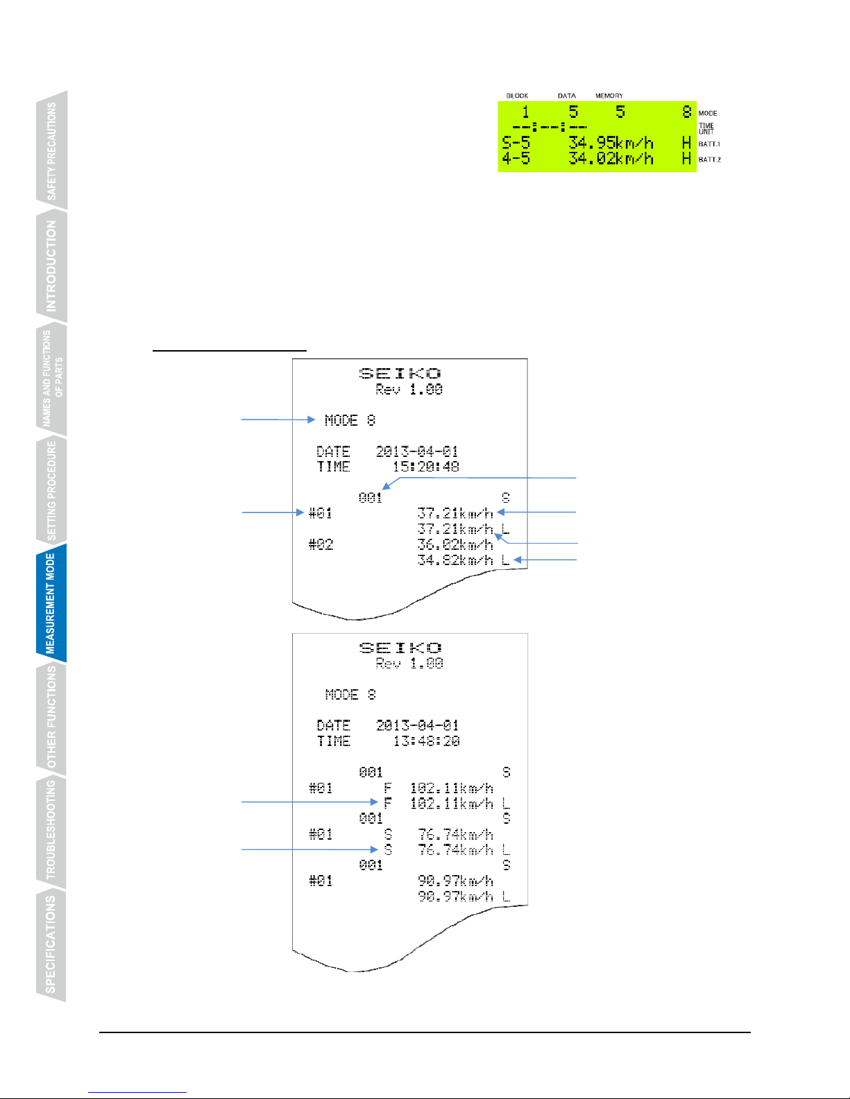
The average speeds in the distance from the start
to a given section and in such section only are measured.
* If the speed below the lower limit ([min]) or above the upper limit ([max]) of the normal
speed range you have set is measured, the speed measurement on the printout is
marked with [S] or [F], respectively.
For the setting procedure, refer to【4.3 Measurement Mode Setting】on P. 19.
5.8.3 Example Printout
Measurement
mode
Block No.
Section speed mark
Average speed from start
Average speed in section
Section No.
Input CH
* The lower limit ([min]) and the upper limit ([max]) of the normal speed range is set to
80 km/h and 100 km/h, respectively.
Outside range
mark
Outside range
mark
Page 45
- 41 -
6. OTHER FUNCTIONS
6.1 Start Time Setting
z Start time other than “0” second can be set.
z This function is available in the following measurement modes:
・ Counting Mode (Measurement Mode No. 1)
・ Parallel Counting Mode (Measurement Mode No. 2)
・ Parallel Lap/Split Time Measurement Mode (Measurement Mode No. 3)
6.1.1 Operating Method
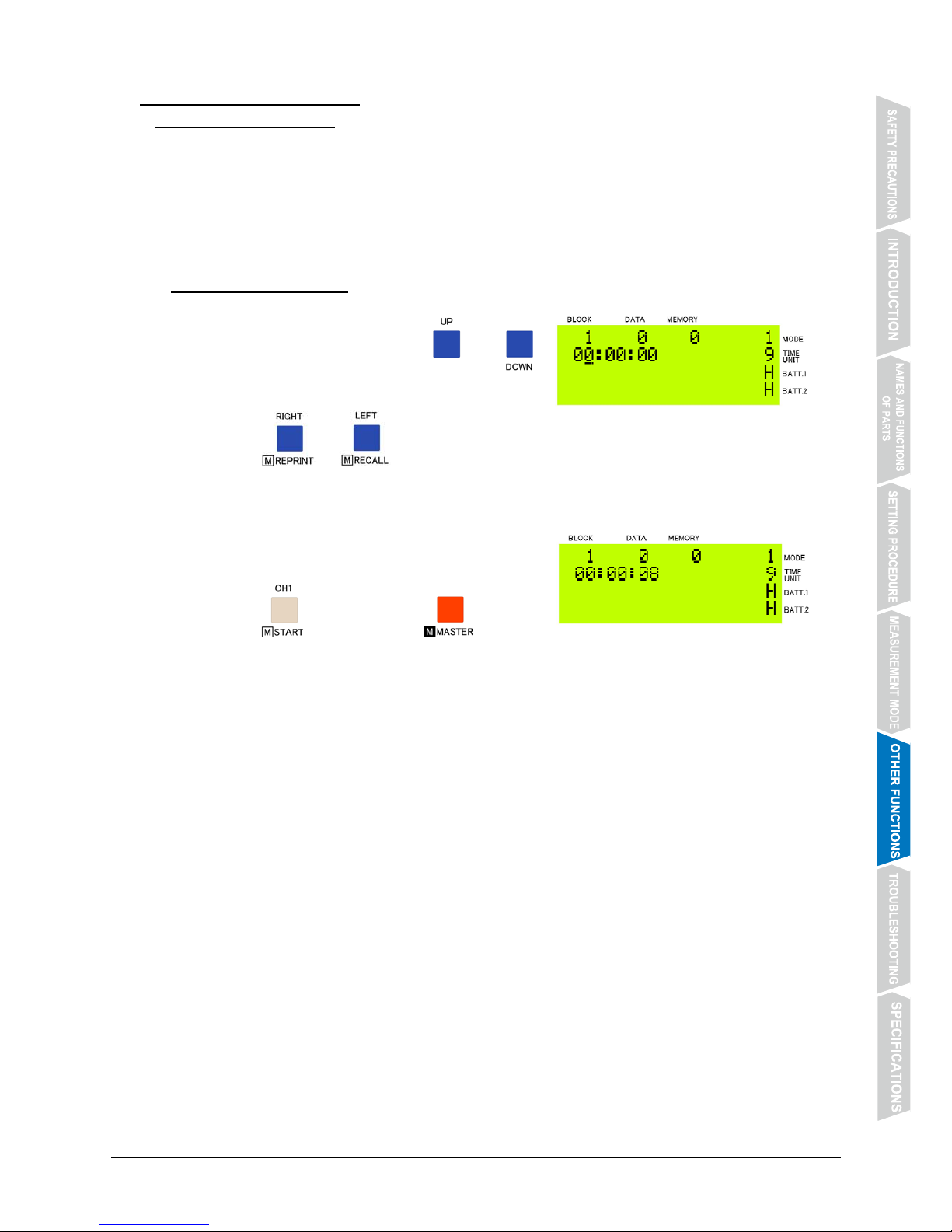
① Set the start time.
Before starting the timer, press @@@ or @@@
to set the time digits.
Press @@@@ or @@@@ to move the cursor.
② Start the timer.
Input a start signal from an external device, or
press @@@@ while keeping @@@@ pressed
to start the timer.
* When the start time other than “0” second is set and [Down] is selected as the method of
counting after the set time, the timer counts down the set time until “0” second.
For the setting procedure, refer to【4.3 Measurement Mode Setting】on P. 19.
* While the timer is counting down, time measurement cannot be made.
Page 46
- 42 -
6.2 Resetting Order of Arrival
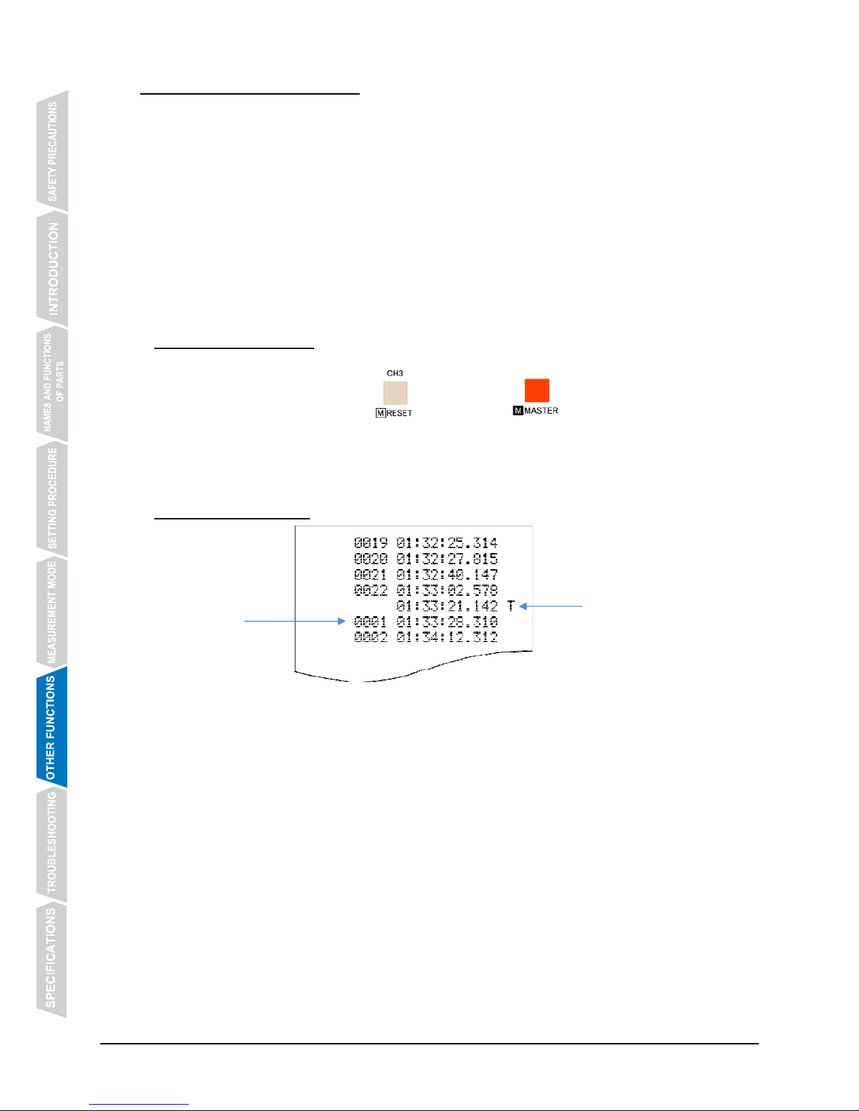
z While the timer is counting, the order of arrival can be reset to increment from “0001” as many
times as necessary.
z This function is convenient when only one unit of CT-2000 is used to measure times at more
than one points such as intermediate and finish points.
z This function is available in the following modes:
・ Counting Mode (Measurement Mode No. 1)
・ Parallel Counting Mode (Measurement Mode No. 2)
・ Parallel Lap/Split Time Measurement Mode (Measurement Mode No. 3)
・ Parallel Delayed Start Mode (Measurement Mode No. 4)
・ Time Correction Mode (inputting time difference from start time) (Measurement Mode No. 5)
6.2.1 Operating Method
While the timer is counting, press @@@@ while keeping @@@@ pressed to reset the order
of arrival to “0001.”
6.2.2 Example Printout
Indication for resetting
order of arrival
Order of
arrival
Page 47
- 43 -
6.3 Inputting Bib No.
z By using a bib No. input device, measured times and bib Nos. can be printed out together.
z This function is available in the following modes:
・ Counting Mode (Measurement Mode No. 1)
・ Parallel Delayed Start Mode (Measurement Mode No. 4)
・ Time Correction Mode (inputting time difference from the start time) (Measurement Mode No. 5)
* For the setting procedure, refer to【4.3 Measurement Mode Setting】on P. 19.
* Please note that, when a bib No. input device is used with CT-2000, up to 3,000 measurement
data can be stored in memory or printed out.
6.3.1 Operating Method
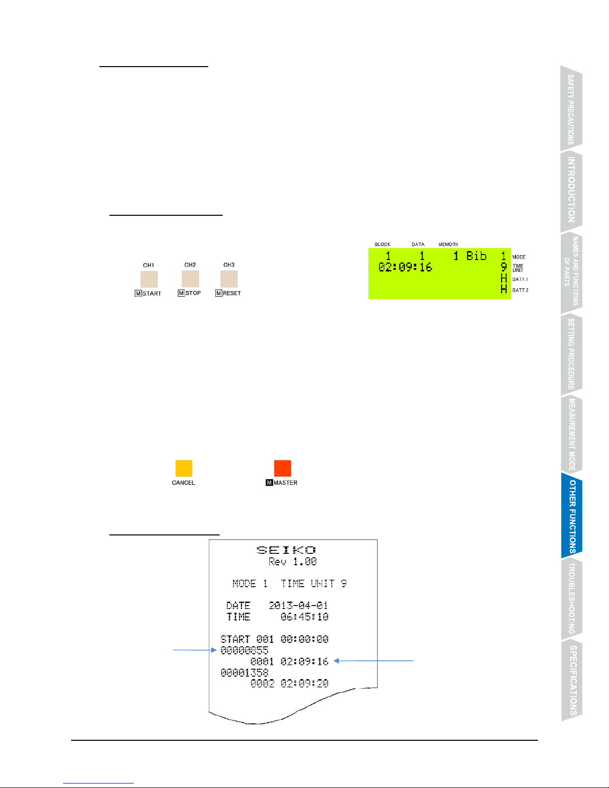
① Measure the time.
Input a CH signal from a grip switch, or press
@@@, @@@ or @@@ to measure the time.
When a time measurement is made, “Bib” is displayed.
② Input a bib No.
When the bib No. is input, the bib No. and the corresponding measurement data is printed
out together.
* The time measured will not be printed out until the bib No. is input.
* One bib No. can be input in advance before the time measurement is made. If more
than one bib No. is input, the one input last is retained.
To skip input of bib No.:
Press @@@@ while keeping @@@@ pressed.
The measured time is printed out without bib No.
6.3.2 Example Printout
Measured time
Bib No.
Page 48
- 44 -
6.4 Memory Recall
z The measurement data stored in memory can be recalled and checked on the display of the
monitor section.
* When no data is stored in memory, or while the timer is counting in any of the measurement
modes, the memory recall function is disabled.
6.4.1 Operating Method
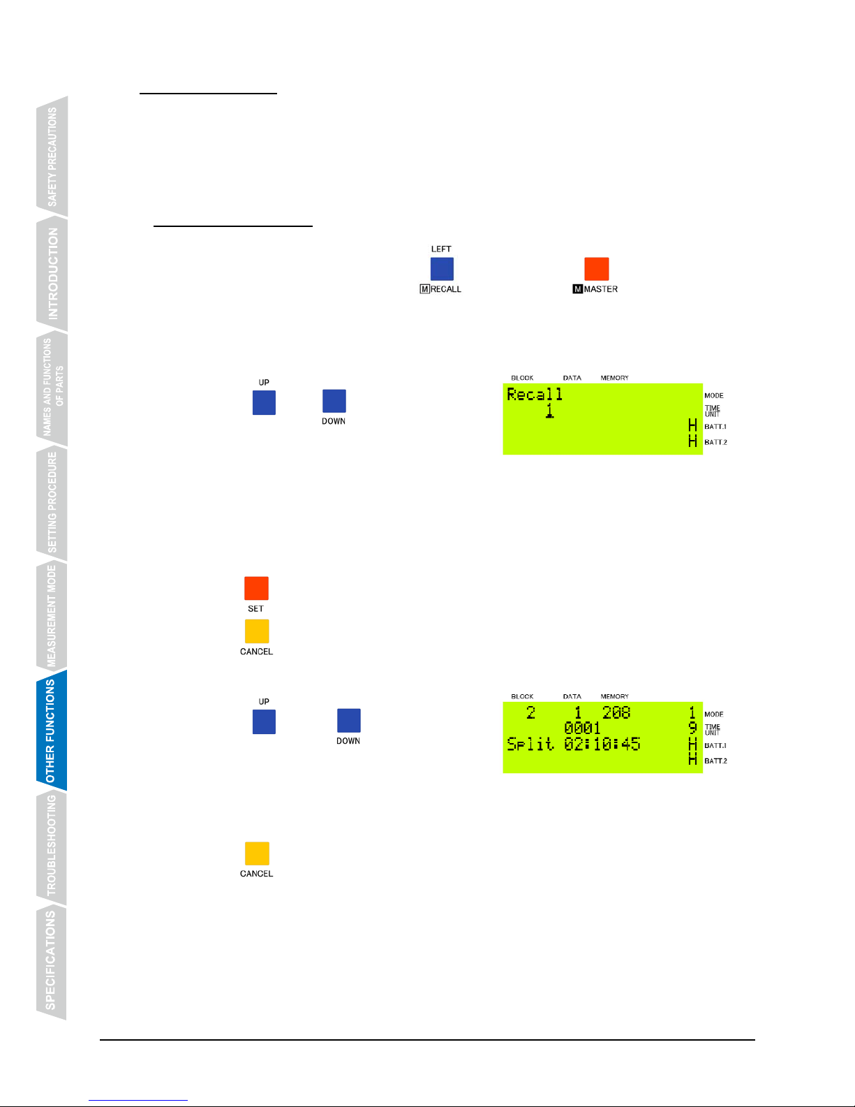
① Activate the Memory Recall Mode.
When the timer is stopped, press @@@@ while keeping @@@@ pressed. The
Memory Recall Mode will be activated.
② Select the block No. whose data you wish to recall.
Press @@@@ or @@@@ to select the block
No. whose data you wish to recall.
Block No. is shown one by one in numerical order, and “All” is shown after the last block
No. as follows: 1 → 2 → 3 → … → All
The data in the block No. you have selected can be recalled. By selecting “All”, all the
measurement data in memory can be recalled.
Press @@@@ to register the block No. you have selected.
Press @@@@ to return the display to the measurement mode.
③ Recall the measurement data.
Press @@@ or @@@ to recall the
measurement data contained in the block No. you
have selected.
Press @@@@ to return to the display for selecting a block No.
Page 49
- 45 -
6.5 Reprinting Data in Memory
z The measurement data stored in memory can be reprinted as necessary.
* When no data is stored in memory, or while the timer is counting in any of the measurement
modes, the function to reprint data in memory is disabled.
6.5.1 Operating Method
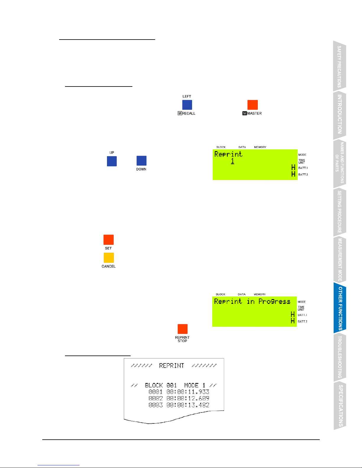
① Activate the Memory Reprint Mode.
When the timer is stopped, press @@@@ while keeping @@@@ pressed. The
Memory Reprint Mode will be activated.
② Select the block No. whose data you wish to reprint.
Press @@@@ or @@@@ to select the block
No. whose data you wish to reprint.
Block No. is shown one by one in numerical order, and “All” is shown after the last block
No. as follows: 1 → 2 → 3 → … → All
The data in the block No. you have selected can be reprinted. By selecting “All”, all the
measurement data in memory can be reprinted.
Press @@@@ to register the block No. you have selected. The data will be reprinted.
Press @@@@ to return the display to the measurement mode.
③ To stop reprinting in progress:
When reprinting of all the data in the block you
have selected is completed, the display returns to
the measurement mode.
To stop reprinting in progress, press @@@@.
6.5.2 Example Printout
Page 50
- 46 -
6.6 How to Clear Data in Memory
z The measurement data stored in memory can be cleared.
* By performing the procedure below, all the measurement data in memory is cleared.
It is not possible to clear the data one by one or block by block.
6.6.1 Operating Method
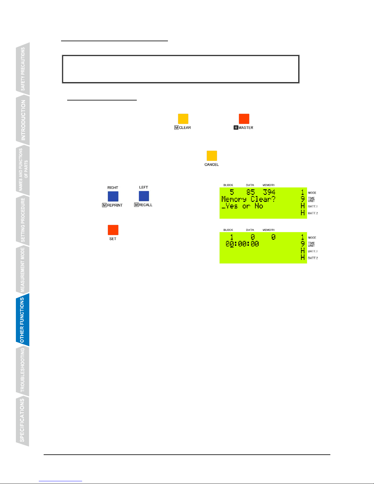
① Activate the Memory Clear Mode.
When the timer is stopped, press @@@@ while keeping @@@@ pressed. The Memory
Clear Mode will be activated.
To cancel the memory clear operation, press @@@@.
② Clear the data in memory.
Press @@@@ or @@@@ to move the cursor
and select [YES].
Press @@@@ to clear the data in memory. The
display returns to the measurement mode.
Page 51
- 47 -
6.7 LOCK Switch
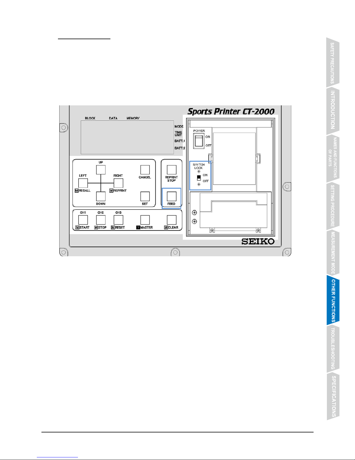
z This switch is intended to prevent mistaken operation of the operation buttons.
z By sliding LOCK switch located inside the printer cover to “ON” position, all the buttons except
FEED button are disabled.
z While the switch is in “ON” position, START and CH signals can be input from external devices
including a grip switch.
z Even while the time measurement is in progress, LOCK switch can be ON or OFF.
LOCK switch
Page 52
- 48 -
6.8 SYNC (Synchronization)
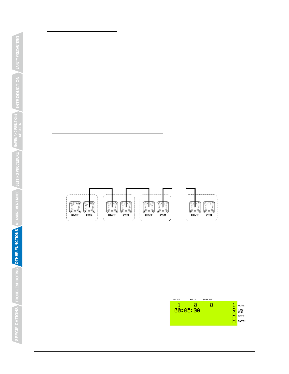
z By outputting a synchronization signal from SYNC connector, more than one unit of CT-2000
can be synchronized.
z Synchronization is achieved via a start signal.
z This function is available in the following measurement modes:
・ Counting Mode (Measurement Mode No. 1)
・ Parallel Counting Mode (Measurement Mode No. 2)
・ Parallel Lap/Split Time Measurement Mode (Measurement Mode No. 3)
・ Time Correction Mode (inputting time difference from the start time) (Measurement Mode No.
5)
* For the synchronization in Time Correction Mode (inputting time difference from start time), refer
to【5.5 Time Correction
Mode 】on P. 30.
* Up to 10 units of CT-2000 can be synchronized with each output of a sync signal.
6.8.1 Method of Synchronization via Start Signal
① Set the start time.
Set the same start time on all the units of CT-2000.
② Connect all the units of CT-2000 with sync cables.
Before inputting a start signal, connect all the units of CT-2000 with sync cables as shown
below.
③ Input a start signal into Master unit.
The start signal input into Master unit is output from SYNC connector to synchronize all
Secondary units.
6.8.2 Method of Synchronization after Start
* Select [Per minute] for the interval between each sync signal output.
For the setting procedure, refer to【4.3 Measurement Mode Setting】on P. 19.
Ex.) To perform synchronization 5 minutes after start
① Set the start time of Secondary units.
Set the start time of Secondary units to
[00:05:00].
Sync cable
・・・
Secondary-1 Secondary-2
Secondary-10
Master
Page 53
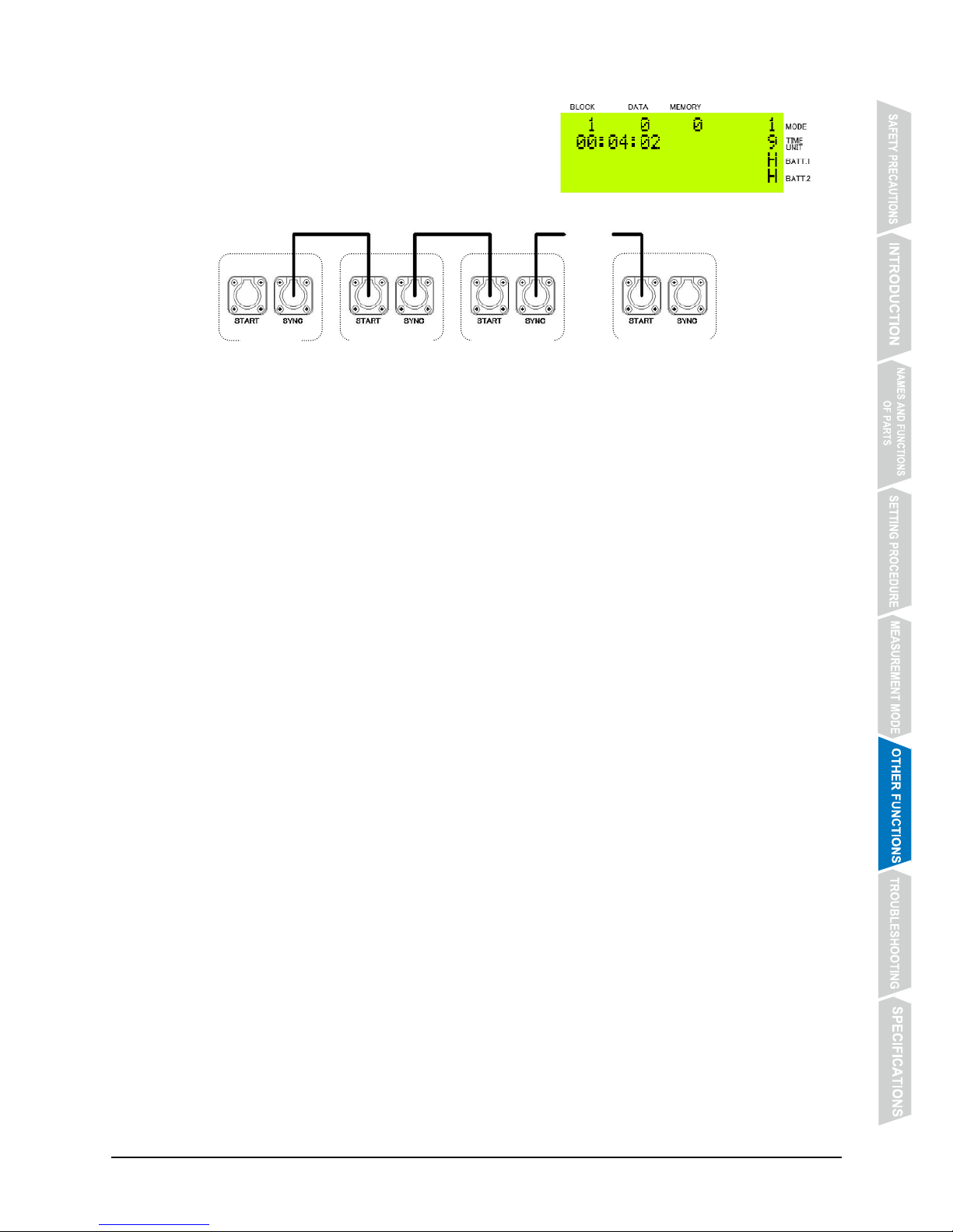
- 49 -
② Connect Secondary units with sync cables.
After the timer of Master unit has indicated
[00:04:00], connect Secondary units with sync
cables.
③ A sync signal is output from Master unit.
A sync signal is output from Master unit to synchronize all Secondary units.
Sync cable
・・・
Secondary-1 Secondary-2
Secondary-10
Master
Page 54
- 50 -
6.9 PC DATA (Output of Data to Personal Computer)
z By connecting a personal computer to PC DATA connector using a USB cable, the
measurement data can be output to the personal computer.
z Use a cable that supports USB 2.0.
* USB cable is an option sold separately.
z CT-2000 has a USB Type B connector.
z CT-2000 uses an FTDI USB-serial converter IC, and it is necessary to install a driver on the
PC.
Download, from the FTDI website below, Virtual COM Port Driver (VCP) that supports the OS
of the PC, and check that it is installed properly on the PC.
http://www.ftdichip.com/
z The measurement data is output to the PC when it is measured or reprinted.
6.9.1 Communication Specifications
Interface USB
Data speed 9600bps
Data length 7 bit
Parity Even
Stop bit 2 bit
Flow control None
Page 55
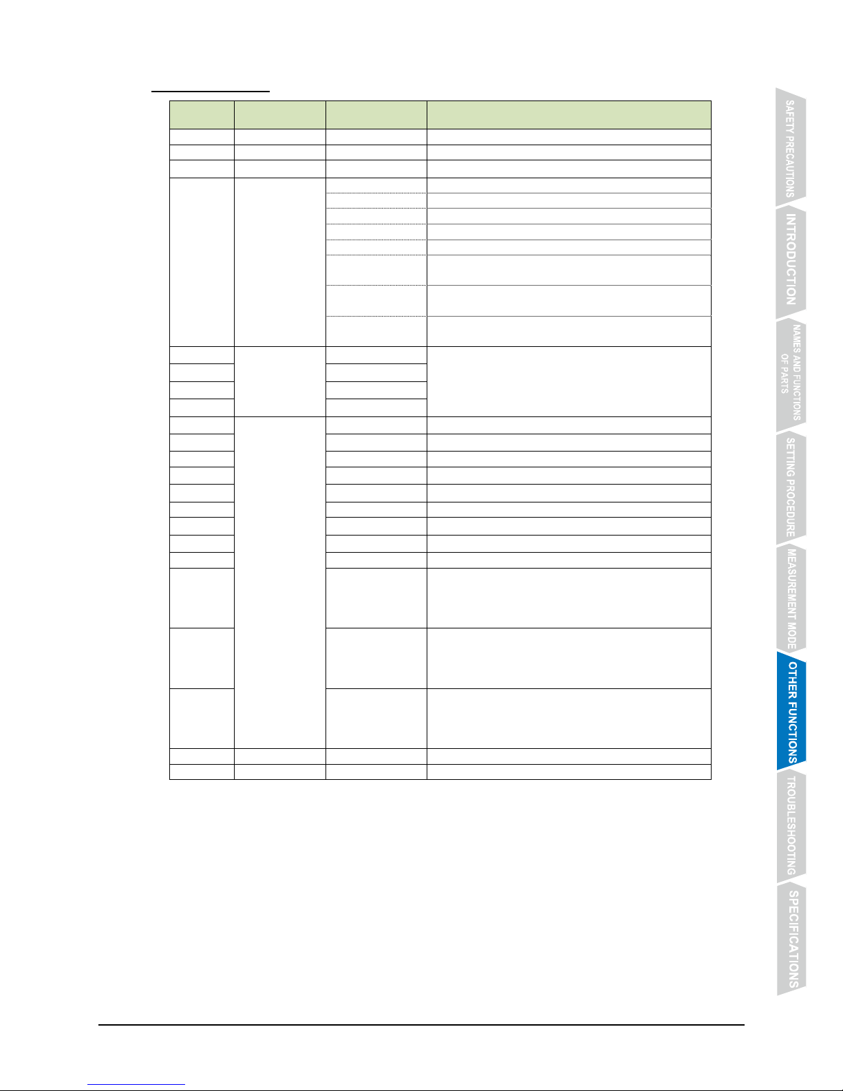
- 51 -
6.9.2 Data Format
No. Data content Value (ASCII) Details
0 START STX
1 UNIT 'X' Model code
2 MODE
'1'~'8'
Measurement mode No.
3 CODE 'R' Reset
'P' Stop
' ' (space) Running
'G' Input CH signal
'C' Print CH data
'N' Print lap time
(Parallel Lap/Split Time Measurement Mode)
'S' Print start time
(Parallel Delayed Start Mode)
'A' Time data when CH signal is input
(Parallel Delayed Start Mode)
4 CHNO
'0'~'9' or ' '
CH signal No. or number of measurements
5
'0'~'9' or ' '
' ' (space) when CODE is 'R' or 'P'
6
'0'~'9' or ' '
7
'0'~'9' or ' '
8 TIME
'0'~'2'
Tens digit of hour
9
'0'~'9'
Units digit of hour
10 ':'
11
'0'~'9'
Tens digit of minute
12
'0'~'9'
Units digit of minute
13 ':'
14
'0'~'9'
Tens digit of second
15
'0'~'9'
Units digit of second
16 '.'
17
'0'~'9' or ' '
1/10 second digit
' ' (space) depending on measurement unit
setting
' ' (space) when CODE is 'C'
18
'0'~'9' or ' '
1/100 second digit
' ' (space) depending on measurement unit
setting
' ' (space) when CODE is 'C'
19
'0'~'9' or ' '
1/1000 second digit
' ' (space) depending on measurement unit
setting
' ' (space) when CODE is 'C'
20 DELIMITER CR
21 STOP ETX
Page 56
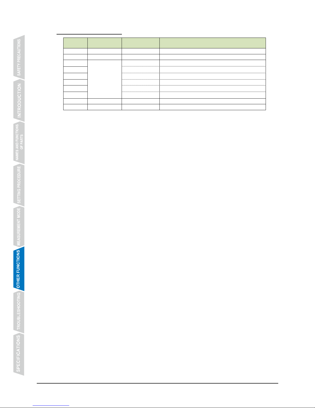
- 52 -
6.9.3 Data Format (Speed)
No. Data content Value (ASCII) Details
0 START STX
1 COMMAND 'Z'
2 SPEED
'0'~'9' or ' '
Hundreds digit
3
'0'~'9' or ' '
Tens digit
4
'0'~'9' or ' '
Units digit
5 '-' or ' '
6
'0'~'9' or ' '
First decimal place digit
7
'0'~'9' or ' '
Second decimal place digit
8 DELIMITER CR
9 STOP ETX
Page 57
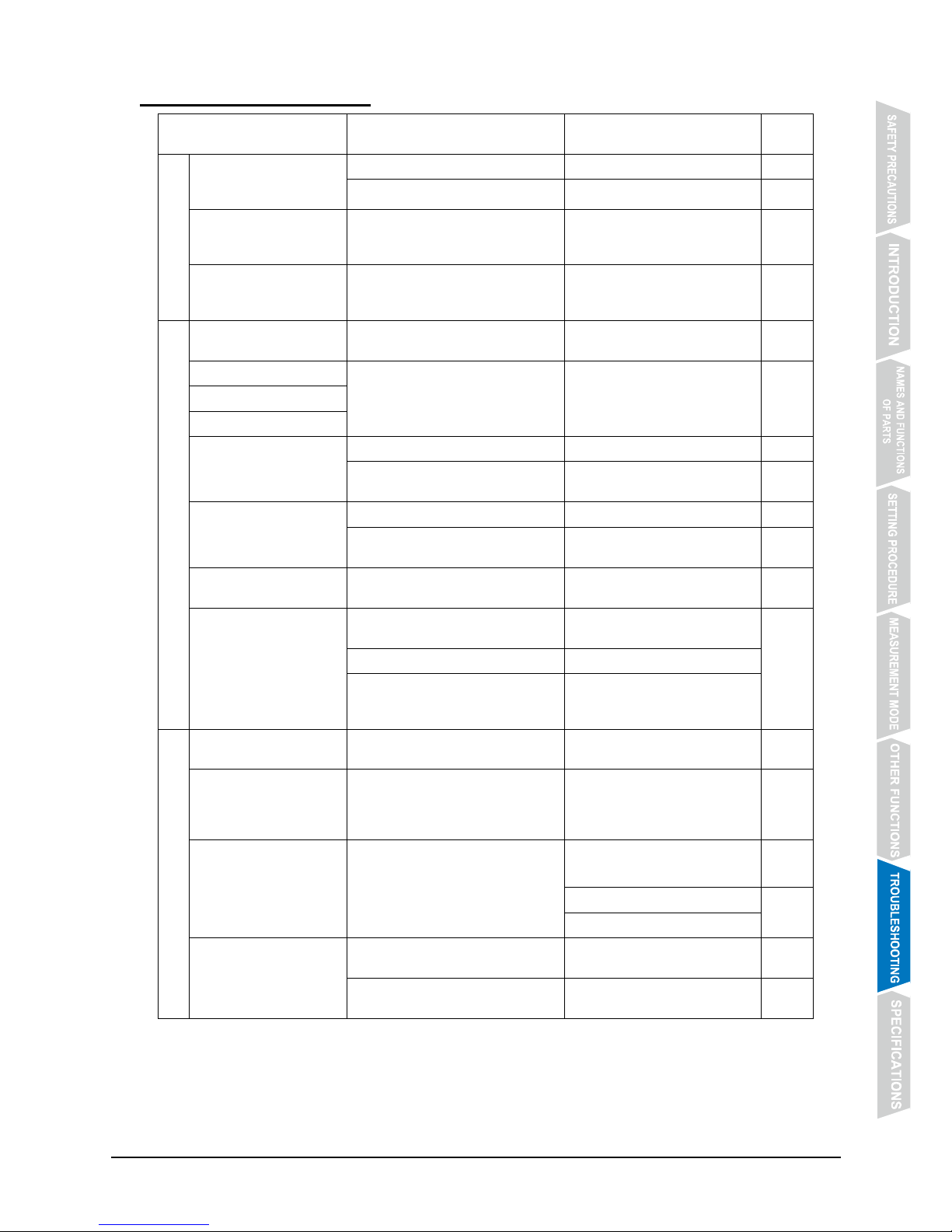
- 53 -
7. TROUBLESHOOTING
Problem Possible cause Remedy
Refer
to
Problem related with
power suppl
y
CT-2000 will not start
operating when POWER
switch is turned ON.
AC adapter is not connected. Connect AC adapter. P. 7
Dry batteries are not installed. Install dry batteries. P. 6
Rechargeable dry
batteries run down earlier
than expected.
It is due to performance deterioration
of rechargeable dry batteries.
Replace rechargeable dry
batteries with new ones.
P. 6
Remaining battery power
indicator does not work
properly.
Dry batteries of other than specified
type are used.
Use batteries of the specified
type.
P. 18
Problem related with operation
Operation buttons will not
work.
LOCK switch is set at “ON” position.
Set LOCK switch to “OFF”
position.
P. 47
Timer will not start.
Respective operation buttons are not
pressed while MASTER button is
kept pressed.
Press respective operation
buttons while MASTER button is
kept pressed.
P. 15
Timer will not stop.
Timer will not be reset.
No signal is output from
connector section.
Cables are not connected properly. Connect cables properly. P. 7
Other than dedicated cables are
used.
Use dedicated cables only.
-
No signal or data is output
from connector section.
Cables are not connected properly. Connect cables properly. P. 7
Other than dedicated cables are
used.
Use dedicated cables only. -
Data is not displayed on
ST-306 scoreboard.
ST-306 has been set wrongly.
Turn off ST-306, and make
proper settings.
-
Measurement data is not
output to PC.
A cable in use does not support USB
2.0.
Use a cable that supports USB
2.0.
P. 50
Driver is not installed on PC. Install driver on PC.
Communication specifications are
not set properly on PC side.
Set communication
specifications properly on PC
side.
Problem related with printer
CT-2000 will not print.
A setting to disable printing is
effective.
Make a setting to enable printing. P. 20
Time digits below decimal
point (fraction of a
second) are printed
inappropriately.
TIME UNIT is not set properly. Set TIME UNIT properly. P. 14
Measured times will not
be printed out by inputting
a CH signal.
“ON” is selected for setting for use of
bib No. input device.
Select “OFF” for setting for use of
bib No. input device.
P. 19
Input a bib No.
P. 43
Skip input of bib No.
Characters print faintly.
CT-2000 is used in low
temperatures.
Warm ribbon cassette. -
Ribbon cassette is depleted or
deteriorated.
Replace ribbon cassette with a
new one.
P. 11
Page 58
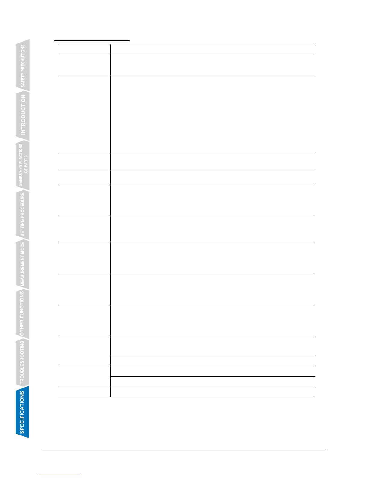
- 54 -
8. SPECIFICATIONS
Time accuracy
Accuracy of crystal oscillator: ± 1 ppm (at a temperature of 25℃)
Maximum
measurement
duration
23 hours, 59 minutes, 59 seconds 999; Start time can also be set in hour,
minutes and seconds up to the maximum duration.
Measurement unit
10 types of
calculation
methods are
available.
Method of calculation Data and printout
1/1000 sec. digit is retained 1/1000 sec. increments
1/1000 sec. digit is rounded down 1/100 sec. increments
1/1000 sec. digit is rounded up 1/100 sec. increments
1/1000 sec. digit is rounded off 1/100 sec. increments
1/100 sec. digit is rounded down 1/10 sec. increments
1/100 sec. digit is rounded up 1/10 sec. increments
1/100 sec. digit is rounded off 1/10 sec. increments
1/10 sec. digit is rounded down 1 sec. increments
1/10 sec. digit is rounded up 1 sec. increments
1/10 sec. digit is rounded off 1 sec. increments
Number of input
channels
From panel
From connectors
:3 channels
:2 channels (up to 10 channels when extension unit is used)
Number of data
storable
Up to 3,000 data contained in up to 100 blocks
Speed
measurement
Distance of section
Measurement unit
Measurement range
Number of input channels
: 1~100 m in 0.1 m increments
: km/h, mph and m/s
: 1~1000 km/h, 1~600 mph, 1~250 m/s
: Up to 10 channels when extension unit is used
Monitor display
Display device
Number of characters
Character height
:LCD
:20 characters x 4 lines
:9.2 mm
Printer section
Printer type
Printing speed
Roll paper
:Dot impact printer (5×7 dot matrix, 24 characters/line)
:2.5 lines/ sec.
:57.5 ± 0.5 mm (width) × 70 mm (outer diameter) or a
smaller size; Plain paper type
Power supply
1. AC 100 V~AC 240 V (used with AC adapter)
2. Built-in battery (2 sets of 6 AA size dry cells) * Rechargeable type batteries
can also be used.
3. External battery (DC12V) *Do not use AC power supply at the same time.
Battery life
Alkaline dry batter: Approximately 8 hours (at +25℃)
Nickel-metal hydride rechargeable battery: Approximately 14 hours (at +25℃)
* The above battery lives may be shorter if measurement/printing is performed
more than once in 10 seconds.
Temperature
range
During operation
: -5℃~+40℃ (non-condensing) * 0℃~+40℃ for AC
adapter
During storage
: -15℃~+55℃ (non-condensing)
External
appearance
Outer dimensions 440 (W) × 467 (H) × 120 (D) mm
Material Resin
Weight
Approximately 5.5kg (excluding batteries)
Page 59

- 55 -
Page 60
I-6667-1E
If you have any question, inquiry or request for
repair regarding the Sports Printer CT-2000,
please contact your SEIKO dealer or agent.
- - - - - - - - - - - - - - - - - - - - - - - - - - - - - - - - - - - - - - - - - - - - - - - - - - - - - - - - - - - - - - - - - - - - - - - - - -
GUARANTEE
Thank you very much for purchasing SEIKO SPORTS PRINTER CT-2000.
We certify that the Product is guaranteed against defects in material and workmanship according
to the guarantee conditions specified herein.
If the Product malfunctions under normal use as described in this Operating Manual within one
year from the date of purchase, it will be repaired without charge.
To qualify for the services under the guarantee, you must present your SEIKO SPORTS
PRINTER CT-2000 to the retailer from whom it was purchased, or a service facility
designated by us. Packaging and transportation charges are to be paid by the owner of the
Product.
Even within the guarantee period, repair services will be provided at cost in the following
cases:
(1) Failure or damage caused by misuse or carelessness;
(2) Failure or damage caused by improper repair or modification;
(3) Failure or damage caused by improper handling such as dropping of the Product during
transportation after purchase;
(4) Failure or damage caused by natural disasters such as fire, flood, earthquake and
lightning, and other factors beyond the control of us such as smoke and other air pollution
and extraordinary atmospheric pressure;
(5) Scratches, cracks or other damage on the case caused by use over time;
(6) If the name of the retailer and the purchase date are not indicated in the space below, or if
such information has been rewritten; and
(7) If this Guarantee is not submitted together with the Product.
Please note that this Guarantee is valid only if the name of the retailer and the date of
purchase are properly entered by the retailer from whom your SEIKO SPORTS
PRINTER CT-2000 was purchased.
Date of purchase:
Retailer:
 Loading...