

Page 1
Operating
Instructions
For
CH
CH-2B
CH-2B/DF
CH-6B
CH-7B
CH-8B
Series
CH-2-RF
<f
h
SEIKO
SEWING
TOKYO•JAPAN
MACHINE
CO.,
LTD.
Page 2
Specifications
of
CH
Types
Sewing
Needle
Number
Sewing
Hook:
Bobbin:
Thread:
Feed
Stitch
Presser
Presser
Thread
Thread
Needle
Bed
Bed
Working
Net
JIS
Motor:
Motor
V
speed;
type:
of
type:
system:
length:
foot:
lift:
take-up:
take-up
bar
shape:
size:
space:
weight
classifications:
pulley:
Belt:
Applications:
needle:
stroke:
(head
stroke:
only)
Max. 800
the
models
DD X 1
(Needle
to
the
Single
Lockstitch
Oscillating
CH
Type
s.p.m.
and
applications.)
#24-25,
type
standard
may
threadstobe
needle
large
(240 x 30.3
Cottonorsynthetic
(SB) Needle,
(7B)
(6B)
(2B)
Needle,
Lower
Upper&lower
(2B/DF)
upper&lower
Lower
feed,
Upper&lower
(Capableofintermediate
Max.
10mm
(SB) Alternating
(7B)
Flat
foot
(6B)
Roller
footorflat
(2B) Alternating
(2B/DF)
20mm
Cam
90.5mm
51mm
Cylinder
820X600mm
200mm
65Kg
LS3
400W.
6O0(5OHZ)
M62
Suitable for
luggages,
by
type
-
ditto
knee
lifter
bed
(tubular
x
400mm
4P
clutch
5O0(6OHZ)
sewingofshoes,
ultra
(Max.
differ
used
hook
width)
fiber
reverse
foot
foot
-
motor
heavy
sewing
#24
from
and
feed,
reverse
feed
feed,
reverse
feed,
(walking
foot
(walking
(10mm
type
materials.
speed
the
the
feed,
will
above
types
materials
reverse
feed
be
changed
being
feed
according
sewn.)
feed
reverse
feed
shirring)
foot&presser
foot&presser
by
lever)
foot)
foot)
820)
bags, satchels, sport-goods,
by
Page 3
Contents
1 Lubrication 1
2 Needle 1
3 Thread 1
4 Insertion
and
Removal 2
5 Winding the Bobbin Thread 3
6 Upper Threading 3
7 Tension of Bobbin Thread and Needle Thread 4
Adjusting Needle Thread Tension 4
Adjusting Bobbin Thread Tension 4
8 Pressure of Presser Foot 5
9 Adjustmentof Stitch Length 5
10 Timing of Thread Tension Releasing Mechanism 6
11
Removal of Shuttle Race Body 6
12 Adjusting on
(A)
(B)
(C)
(D)
the
Each Points 7
Adjusting Needle Position Against Needle Hole of 7
the
Feed
Dog
{7B & 8B
Types)
Adjusting of Feed Dog Height 7
Adjusting theForward and Backward Position of q
Needle
BarFrame
Timing of Needle and Hook 8
13
14
CH-2B/DF
a. Use of
b. Adjusting Upper Feed Length Against Lower Feed 11
CH-2-DF
Positioning of
Adjusting
Adjusting
needle
the
height of needle bar 9
the
position of
and
tip of
the
Clearance between needle
Each timing for up/down strokes of
foot
the
Length
Adfusting
Adfudting
Positioning
Adjustment
Adjusting
(2B & SB
Differential Feed Mechanism 10
Types
Upper
Lower
Up/Down
Feed
Feed
Upper
only)
Length
Length 12
Feed
Dog 13
Amount
the
hook 9
tip of hook 9
and
tip of hook 9
presser
of
Upper
Feed
10
11
11
14
14
Positioning
presser
Bar
15
Page 4
1
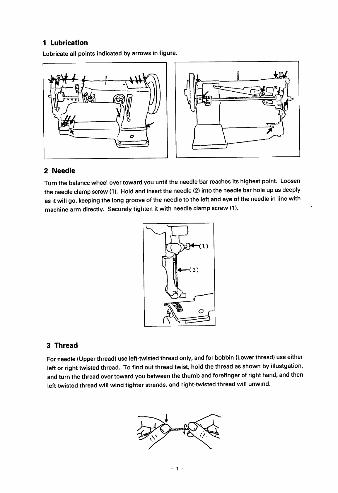
Lubrication
Lubricate all points indicated by arrows in figure.
2
Needle
Turnthe balance wheel over toward you untilthe needle bar reaches its highest point. Loosen
the
needle
asit
machine arm directly. Securelytighten itwith needle clamp screw
will
clamp
go,
screw
keeping
the
(1).
long
Hold
groove
and
insert
ofthe
the
needle
needle
(2)
tothe
into
left
the
and
needle
bar
eyeofthe
(1).
holeupas
deeply
needleinline
with
3
Thread
For
needle
leftorright
andturnthe thread overtowardyoubetweenthe thumbandforefinger of
left-twistedthread
(Upper
twisted
thread)
will
use
left-twisted
thread.
To
find
wind tighter strands, and right-twistedthread
out
thread
thread
only,
twist,
1 -
and
hold
for
bobbin
the
threadasshownbyillustgation,
(Lower
will
thread)
right
hand,andthen
unwind.
use
either
Page 5
4
Insertion
§
RemovalofBobbin
and
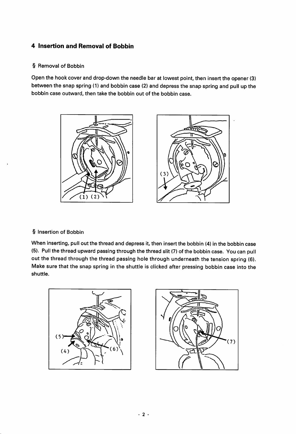
Removal
of
Bobbin
Open the hook cover and drop-down the needle bar at lowest point,then insert the opener (3)
between the snap spring
bobbin
case
outward,
then
(1)
and bobbin case
take
the
bobbin
(2)
and depress the snap spring and pull up the
outofthe
bobbin
case.
§
InsertionofBobbin
When inserting, pull
(5).
Pull
the thread upward passing through the thread slit
out
the
thread
and
depress
it,
then
insert
the
bobbin (4) in
(7)
of the bobbin case. Youcan pull
the
bobbin
case
out the thread through the thread passing hole through underneath the tension spring (6).
Make sure
shuttle.
that
the snap spring in the shuttle is clicked after pressing bobbin case into the
2 -
Page 6
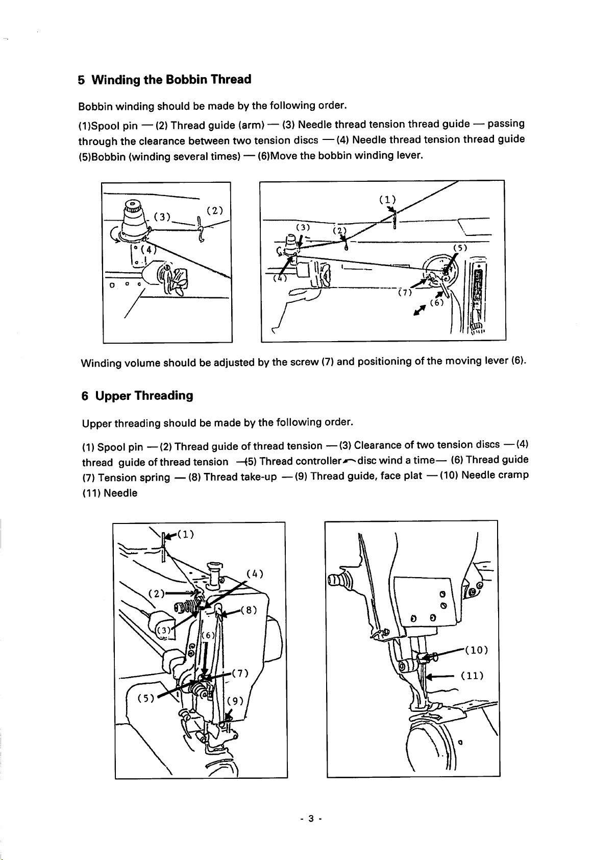
5
Winding
Bobbin winding should be made by the following order.
the
Bobbin
Thread
(l)Spool pin —
(2)
Thread guide
(arm)—(3)
Needle
thread tension thread guide — passing
through the clearance betweentwo tension discs —(4)
(5)Bobbin (winding several times) — (6)Move
Winding
6
Upper
volume
Threading
shouldbeadjusted
bythe
the
bobbin winding lever.
screw
(7)
and
Needle
thread tension thread guide
A
positioning
ofthe
moving
lever
(6).
Upper threading should be made bythe following order.
(I)
Spool
thread guideofthreadtension
(7)
Tensionspring —
(II)
Needle
pin
—(2)
\|1^(1)
Thread
guide
ofthread
—(5)
(8)
Thread take-up —(9)Thread guide, face plat —(10) Needlecramp
Thread
tension
—(3)
controller-*^disc
Clearanceoftwo
wind
a time—
tension
(6)
discs
Thread
—(4)
guide
- 3 -
Page 7

7
Tension
(A)
When stitch tension is well balanced, the bobbin thread is engaged with the needle thread
at
the
center of given material thickness, as
of
12^
Bobbin
Thread
and
Needle
shown
Thread
(A)
(B)
Balanced
by Fig.
Tight
needleofloose
tension
(A)
bobbin
thread
tension
(B) Fig. (B)
(C)
Fig.
shows
(C)
shows unbalanced tension, loose needle thread or tight bobbin thread.
unbalanced
tension,
§ Adjusting Needle Thread Tension
n
To adjust tension of needle thread, turn Tension Regulating
Thumb.
By
increases'-^.
By
tension
tight
turning
turning
decreases-*^.
needle
the
the
thread
(C) Loose
knurling
knurling
or loose
needleortight
nut
clockwise,
nut
counter-clockwise,
bobbin
bobbin
needle
thread.
thread
thread
needle
tension
tension
thread
§ Adjusting Bobbin Thread Tension
To
adjust
Regulating
By
regulating
be
tightened
adjusted.
By
turning
tension
clockwise'^,
loosen
increases,
tensionofthe
Screw.
set
screw
screw
the
(2).
after
tensionofthe
set
screw
The
and
bobbin
thread
bobbin
(1)
clockwise—^,
turning
set
thread,
and
screw
the
tension
turn
adjusting
(1)
should
bobbin
bobbin
set
screw
decreases.
Tension
tension
thread
counter
- 4
exactly
was
thread
Page 8

8
Pressure
By
turning
pressure
Tension
Adjustment
9
regulating
Adjustment
of
Presser
the
pressure
regulating
should
Foot
regulating
thumb
nut
be
of
screw
shouldbetightened
madetosuit
Stitch
Length
thumb
counter-clockwise^^,
for
screw
the
clockwise'-^,
after
pressure
materials
pressure
being
was
sewn.
pressure
decreases.
adjusted.
increase,
and
turning
By pull-up t feed regulating lever (1), reverse stitch is performed, and push-down feed I
regulating
By
turning
(2) & (3)
Knurling
lever
(1),
forward
knurling
counter-clockwise<«^,
nut
(2) & (3)
nut
(2) & (3)
shouldbetightened
stitchisperformed.
clockwise'^,feed
feed
length
increases.
each
other
length
after
decreases,
desired
and
turning
stitch length
knurling
was
determined.
nut
(Note)
When
regulating
should
upward
leverisloosened,
be
tightened.
- 5
&
downward
moving
feed
of
adjustin
the
screw
feed
(4)
Page 9

10 Timing of Thread Tension Releasing Mechanism
(a)When moving the liftinglever (1)for knee
lifter,
upper
(b)
Adjustment
thread
is adjusted to loosen.
Pull-up
the
presser
bar
lifter (3),
clearance
should be made over 1 mm between tip of
the
tension releasing plate
and
then
tighten
tension
releasing
11 Removal of
the
plate.
Shuttle
and
screws
Race Body
tension disc,
(2)
on
the
Tighten the shuttle race back spring screw
screws (2)and remove
(Note)
the
shuttle race body and shuttle hook.
(1),
then loosen and take offthe two shuttle race
In
caseofthe
removal of
shuttle
race body,
U
without tightening of shuttle race back spring
screw
(1),
spring
the
shuttle
shuttle
may
race
run
out
race body.
back
and/or
and
may
shuttle
difficult to
race
back
set
The shuttle race backspring screw (1)is surely
loosened, while the materials are being sewn.
Page 10

12
Adjusting
(A)
Adjusting
Needle
with
(a)
(b)
on
Needle
should
the
feed
Loosen
moving
Loosen
holeoffeed
feed
(push-inorpull
feed
the
Each
Position
be
positionedatthe
dog.
(upper)
(upper)
dog,
then
Points
Against
shaft
out)offeed
shaft
connector
tighten
Needle
centerofneedle
connecting
(upper)
(A)
the
screw
Hole of
screw
shaft
screw
(3).
the
Feed
holeoffeed
(2),
upper
connector
(3),
and
Dog. {7B & 8B
dog
feed
length
(B) (1).
needle
setatthe
Types)
and
moved
will
differbythe
centerofneedle
together
(Needle
setatthe
of
(B)
Taking
The
lowest
In 6B. 2B
The
lowest
dropping
center
the
feed
AdjustingofFeed
off
the
heightoffeed
pointofneedle
types;
heightoffeed
pointofneedle
dog.)
pointisto
of
needle
Dog
needle
in 7B
dogisadjusted
barbyfeed
dogisadjusted
bar.
be
hole
Height
and
(Note)
Feed
(upper)
is
tightened
rightward.
8B.
1.3mm-1.5mm
dog
height
1.3mm
shaft
for
the
adjustable
-1.5mm
connector
(A) (4) is fixed
preventionofthe
above
above
the
surfaceofthe
screw
(1).
the
surfaceofthe
n
and
movingofleftward
throat
troat
the
screw
plate,atthe
plateatthe
(3)
and
RefertoRemovalofShuttle
Race
Body
m
l.Smm
-
1.5nim
- 7
Page 11

(C) Adjusting
the
Forward
and
Backward Position of Needle Bar Frame
Correct position
between
presser
between
bar
and
needle
needle
bar
bar
being
frame
and
16mm
Adjustment
needle
baristobemade
presser
under
of
the
barisdeterminedbythe
the
stitch length being "0"
clearance
by
between
the
screws
presser
(1).
distance
mm.
bar
and
(D)
TimingofNeedle
Positioningofneedle
When
should
Adjusting
Loosen
adjust
the
needle
meet
the
the
screwofbar
the
needle
bar
the
center
Distance
the
heightofneedle
bar
and
Hook
and
tipofthe
has
risen
4.5mm-5.5mm
Lineofthe
between
hook
shall
be
bar
connecting
(3)(upward
hook
needle.
U
the
upper
2.5mm-3mm.
stud
(2) by
and
downward.
from
2.5imD~3nn
4.5inD~5.5min
tipofthe
wrench
its
lowest
needle-eye
position,
which inserts to
and
the
the
the
hole (1) of
tipofthe
tip
of
hook
arm
and
Adjusting
Loosen
then
Tighten
the
the
screw
determine
the
screw
positionofthe
(5) of
the
forwardnessorbackwardness
(5)
after
the
shaft
adjustment.
tipofhook
crankbythe
spanner
- 8
which
(high
speedorlow
insertstothe
speed)ofthe
hole
(4) of
the
tipofhook.
head,
Page 12

©
T
Clearance
In 7B & 8B
Loosen
needle
and
needle
rock
the
needle
After
hinge
bar
rock
And,
frame
If
the
resultedinthe
between
types;
the
set
bar
rock
also
the
bar
rock
frame
leftward
bar
determination
stud,
and
frame
put
the
(2),
and
looseness
needle
Determinationofthe
screw
frame
set
screw
frame
and
(1)ofthe
hinge
(7)ofthe
hinge
& rightward-**,
and
adjust
then
position
needle
then
of
breakingofneedle,
the
of
the
put
the
bracket
bar
rock
turn
the
the
leftward&rightward-*-^of
tip
of hook;
needle
stud
(small) (4)
needle
stud
(large)
and
clearance
clearance,
needle
(8).
frame
hinge
balance
stitch
0.05mm-0.3mm
positionofneedle
bar
rock
frame
positioned
bar
rock
frame
(6)torightward
turn
the
balance
between
tighten
bar
wheel
rock
the
frame
stud
(large)
and
tighten
skipping.
needle
set
hinge
(6)tothe
the
hinge
lower
hinge
wheel,
and
screw
stud
the
needle
0.05mm
bar
rock
frame.
stud,
and
partofneedle
stud
(large) (6).
and
also
determines
tipofthe
(2) of
the
(small)
side
faceofthe
each
screws
bar
the
set
bar
Then,
moving
smooth
hook.
needle
(4)toslightly
exactly.
should
happen,
screw
rock
the
bar
needle
(5)ofthe
frame
moving
needle
position
rock
frame
the
needle
bar
it will
(2),
the
bar
of
rock
be
0.3mm
Page 13

Each
timing
a.
Timing
to
feed
you.
Adjsutmentismadebythe
for
up/down
of walking
dog,
after
strokesofpresser
footisadjuted
downing
the
two
foot
walking
foot
leverofpresser
stopper
screwsofcam
(2B & 8B
types
reachtofeed
bar
lifter,
(1) {upward &
only)
dog
turning
before
the
balance
needle-eye
wheel
downward).
reaches
Byup &down the presser cam (upward & downward) fI , walkingfoot against needle is
touchingtofeed
As for 2B
of
the
b.
For
crank
Adjustmentistobemade
throat
the
pinch
type,
setting
dog
speedily
adjusting feed
plate.
walking
screw
(2) is tobeadjusted.
foot
by
and
dog
and
the
slowly.
and
presser
presser
materials
foot
being
foot to
set
equivalent,
sewn.
equivalent
the
lifting
point on
eccentric
the
upper
connection
toward
face
c. Up/down strokes of walking foot and
screw
(3),
the
stroke increases,
downIthe
s
presser
foot is loosened by the screw (3) and up f
screw
(3),
the
stroke
decreases.
the
a.
Useofthe
Pull-down
volume
Pull-down
length.
(e.g..
Lower
Adjusting
Turn
the
Turn
the
Fixed
positionoffeed
Differential
the
the
feed:
Upper
chain
chain
10mm,
Feed
(1),
(1),
Length
Feed
upper
upper
Upper
dial (2) clockwise'-^.,
dial (2)
counter-clockwise-^,
lengthisadjustedbystopper
Mechanism
feed
feed
feed:
upper
volume
length
18mm)
feed
length
upper
increases
increases
decreases.
feed
length
10
(3)
by
maximum
by
maximum
increases.
and
stopper
80%
nut
80%
(4)
against
against
lower
lower
feed
feed
Page 14

b. Adjusting Upper Feed Length Against Lower Feed Length
For adjusting equivalent
Adjustment
Turn
the
Turn
the
(Note)
Over
turningofstopper
that
the
is to be
stopper
stopper
topoffeed
madebythe
screw
screw (3)
adjusting
the
upper feed length against lower feed length.
stopper
(3) clockwise^-'^,
counter-clockwiseupper
screw
(3) &
lever
touch
screw
upper
stopper
with
(3)
and
stopper
feed length increases.
feed length decreases.
nut
(4)
counter-clockwise
the
feed
upper
shaft
nut
(4).
connector.
will
cause
the
troubles
CH-2-DF
© Adjusting Upper Feed Length
1.
Coarse
regardless
stitchofupper
of
lower
feed.
feed
length
canbeperformed
r
(A)
by pull
down
the
lifting
nB
lever
(A),
11
Page 15

2.
Upper
*{C)
*The
feed
position
comes
position
position
shouldbeset
in
contact
of shirring
can
be fixed by (B) & (C).
equivalently
with
(C).
amount
for
the
with
lower
materials
feed
being
length
sewn
on
the
canbeset
condition
by (B). (Fig. a & b)
that
pin
(D)
large
\
^1
3
1
small/ I
rr
II
0
Fig. a
Fig.b
3. In case of unifying of shirring amount and/or general sewing (equivalent with lower feed),
pin (D)
should
be fixed by
pinching
(B) & (C). (Fig. d)
© Adjusting Lower Feed Length
Loosen
turn
the
feed adjusting nuts
them
counter-clockwise,
(A)&(B)
feed
length
and
turn them clockwise, feed length decrease and
increase.
Fig. d
After
pulled
machine
touches
adjustment,
down
on
the
with
plate
the
exactly,
condition
(C).
lever
then
should
operate
that
nut
be
the
(A)
0
Lever
-
12
«
Pull
down
Page 16

©
Adjustment
Loosen
made by
groove
Set
the
change
position (B).
screw
set
screw,
(A)
shouldbetightened
(turn)
adjustment
the
can
be
screw driver
without
any rattle or the leftward & rightward of
the
upper
feed
arm
(C).
@
Wrong
©
Adjusting
Loosen
(8)
^ a
nut
(A),
clockwise,
decrease, turn
up/down
After
tightened
amount
adjustment,
exactly.
Up/Down
turn
the
it^b
increase.
nut
AmountofUpper
adjusting
up/down
counter-clockwise,
(A)
screw
amount
should
be
Feed
(K)
More
than
(A)
(B)
-
14
-
Page 17

© Positioning of
Presser
Bar
Clearance
and
presser
Lay
<E)
(F)
and
Clearance
1,
5mm
between
bar
guide
& (F)onarm,
(G)
should
(H)
should
upper
should
clearance
be
2mm.
be
more
feed
arm
be
1.5mm.
between
than
(C)
3mm.
u
1.
5inni
15
Page 18

SEIKO
SEWING
MACHINE
CO.,
LTD.
Head Office : 11-3,
Show
Room
Osaka
Branch
Show
Room
Telex:
: 21-7,
: 5-10,
: 5-10,
Imado
1-chome,
2657148
Asakusa
Terada-cho
Terada-cho
Talto-ku, Tokyo 111,
SEIKOJCable:
1-chome,
Taito-ku, Tokyo 111,
2-chome,
2-chome,
Japan
SEIKOSEWMCO
Japan
Tennoji-ku,
TennojI-ku, Osaka 543,
Osaka
543,
TOKYO
Japan
Japan
Tel:
03-3872-6173-4
Telefax:
Tel:
Tel:
Tel:
03-3873-6596
03-3872-6493
06-779-7578
06-779-7578
(Export
Dept.)
96033000
<E)
 Loading...