

Page 1
PARTS CATALOGUE / TECHNICAL GUIDE
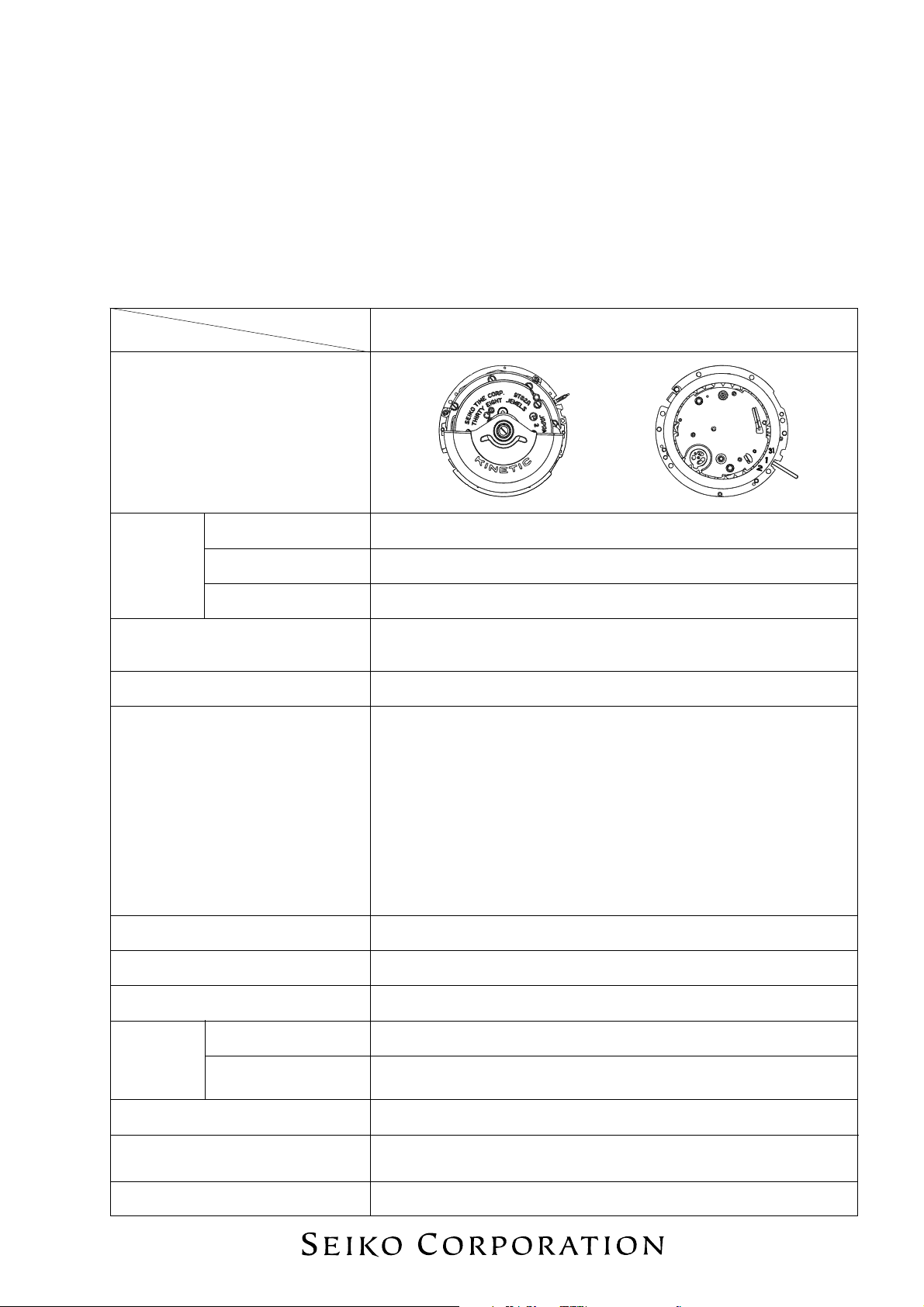
Cal. 9T82A
(For Movement Replacement)
[SPECIFICATIONS]
Cal. No.
Item
Movement
Movement
size
Time indication • Time: Hour, minute and second hands
Driving system Step motor (Load compensated driving pulse type)
Additional mechanism
Outside diameter ø33.0 mm
Casing diameter ø30.0 mm
Height 6.8 mm
• Stopwatch: Stopwatch hour, minute, second and 1/10 second hands
• Automatic generating system
• Stopwatch function with stopwatch hour, minute, second and 1/10
second hands
• Overcharge prevention function
• Energy depletion forewarning function
• Electronic circuit reset switch
• Train wheel setting device
• Date calendar
• Instant setting device for date calendar
• Instant date change mechanism
9T82A
(x 1.0)
Loss/gain Monthly rate at normal temperature range: less than 15 seconds
Regulation system
Measuring gate by quartz tester Use 10-second gate.
Power
supply
Electricity Storage
Unit (E.S. Unit)
Operating voltage range 0.45 V ~ 2.2 V
Duration of charge
Jewels 38 jewels
Logical regulation system
Automatic generating systemPower generator
Titanium lithium ion rechargeable battery
From full charge to stoppage: Approx. 1 month (when the stopwatch
is used for less than 3 hours a day)
1
Page 2
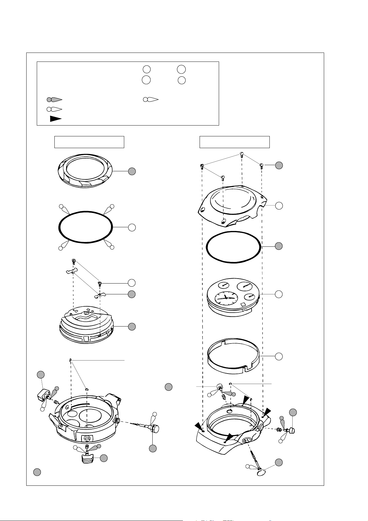
PARTS CATALOGUE
Disassembling procedures Figs. : 1 → 12
Reassembling procedures Figs. : 12 → 1
Lubricating: Types of oil Oil quantity
SEIKO Watch Oil S-6 Normal quantity
Silicone oil 500,000 c.s.
Adhesive (LOCTITE 241)
1 Case back
(page 4)
Cal. 9T82A
One-piece case typeConventional type
1 Bezel screw
(page 5)
2 Bezel
7 Button A
(page 6)
2 Case back gasket
3 Casing clamp screw
4 Casing clamp
(page 4)
6 Movement
(page 5)
Button spring clip
7 Button A
3 Bezel gasket
(page 6)
5 Movement
6 Casing ring
Button spring clip
(page 6)
7 Button B
(page 6)
5 Winding stem
7 Button B
(page 6)
Please see the page shown after the part name.
➡
with crown
(page 5)
4 Winding stem
with crown
(page 6)
2
Page 3
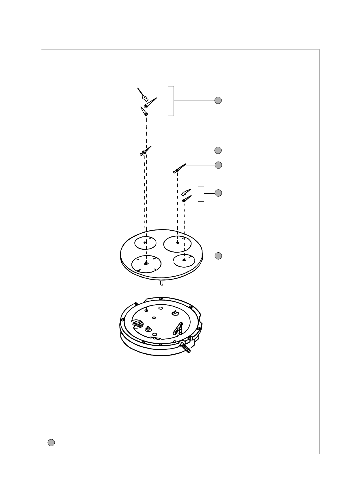
PARTS CATALOGUE
Cal. 9T82A
8 Hour, minute and second hand
(page 6)
9 Stopwatch 1/10 second hand
(page 7)
10 Stopwatch second hand
(page 7)
11 Stopwatch hour and minute hands
(page 7)
12 Dial
(page 7)
* When reassembling the watch, be sure to use a new set of stopwatch hands.
If the old stopwatch hands are reused, they may come off from the shock when they are reset to “0”
position.
Please see the page shown after the part name.
➡
3
Page 4

TECHNICAL GUIDE
I. REMARKS ON DISASSEMBLING AND REASSEMBLING
For conventional type
1 Case back
· To fix the case back to the case, the case back itself is screwed into the case, or the case back screws
are used, depending on models.
· For the models using the case back screws, use the adhesive “LOCTITE 241” to prevent them from
loosening.
Note: Never use an adhesive other than “LOCTITE 241” for fixing the case back screws.
Cal. 9T82A
• How to fix the case back with the case back screws and the adhesive
Case back screw
1. Wipe any adhesive, oil, dust or dirt off the screws and the
holes for screws on the case with alcohol.
2. Before setting the case back to the case, apply a proper
amount of the adhesive to the holes for screws as shown
at right.
3. Set the case back to the case and then, tighten the case
back screws firmly.
* Tighten the screws one by one in diagonal direction.
* After tightening once, give the screws another turn to
fix them securely.
4. Leave the watch untouched at room temperature for
about one day until the adhesive is completely hardened.
Notes:
Adhesive
* Apply only a necessary amount of adhesive to the hole lest it should come out on the case.
* Take care not to let the adhesive stick to the inner surface of the case.
4 Casing clamp
• How to remove
A
Loosen the casing clamp screws at the 3 and 9
o’clock sides and remove the casing clamps.
Case back
Case
Casing clamp
• How to install
Set the casing clamps at the 3 and 9 o’clock positions
as shown in the illustrations at right, and tighten the
B
▼
9 o’clock side
casing clamp screws securely.
Note: The movement is fixed to the case by fitting
B
“A” and “B” portions of the casing clamp
securely in the groove of the case. When
setting the casing clamp to the movement,
therefore, check that “A” and “B” portions
are equally protruded from the movement
▼
A
edge, and then, tighten the casing clamp
screw firmly.
3 o’clock side
4
Page 5

TECHNICAL GUIDE
5 Winding stem with crown
The crown gasket is attached inside the stem pipe of
the case.
• Lubricating
Apply the silicone oil to the portion of the crown as
indicated in the illustration at right. Insert the
winding stem into the stem pipe, and turn the crown
so that the silicone oil is spread thoroughly over the
crown gasket.
6 Movement
When installing the movement into the case, first set its 12 o’clock side to the case and then, other sides.
Otherwise, the movement may not be fitted in smoothly.
For one-piece case type
Cal. 9T82A
1 Bezel screw
• Remarks on the adhesive
· An adhesive is used to fix the bezel screws.
· Be sure to use the adhesive “LOCTITE 241” to fix the bezel screws.
Note: Never use an adhesive other than “LOCTITE 241” for fixing the bezel screws.
• How to fix the bezel screws with the adhesive
1. Wipe any adhesive, oil, dust or dirt off the
screws and the holes for screws on the case with
alcohol.
2. Before setting the bezel to the case, apply a
proper amount of the adhesive to the holes for
screws as shown at right.
3. Set the bezel to the case and then, tighten the
bezel screws firmly.
* Tighten the screws one by one in diagonal
direction.
* After tightening once, give the screws another
turn to fix them securely.
4. Leave the watch untouched at room temperature
for about one day until the adhesive is completely
hardened.
Adhesive
Bezel screw
Bezel
Case
Notes:
* When tightening the bezel screws, use a screwdriver having a flattened tip of a size corresponding
to that of the screws. Take care not to damage the slots of the bezel screws, bezel or case.
* Apply only a necessary amount of adhesive to the hole lest it should come out on the case.
* Take care not to let the adhesive stick to the inner surface of the case.
Lubricating: : Silicone oil 500,000 c.s.
5
Page 6

TECHNICAL GUIDE
3 Bezel gasket
Never apply the silicone oil to the bezel gasket. Otherwise, the silicone oil may spread to the dial or other
parts, causing malfunctions.
4 Winding stem with crown
• How to remove
Push the lever for unlocking stem between the dial and the case vertically down with tweezers, and
remove the winding stem with crown.
For both types
7 Buttons
• Lubricating
Cal. 9T82A
Apply SEIKO Watch Oil S-6 to the end portions of the buttons that touch the lever.
8 Hour, minute and second hands
• How to install the hour hand
The watch is provided with the instant date change mechanism. In order for the date to change at
the exact time, install the hands following the procedure below.
1. Slowly turn the crown counterclockwise.
Stop turning the crown when the date has
changed.
2. Install the hour hand so that it points slightly
ahead of the 12 o’clock marker (See the
illustration at right).
3. Install the minute and second hands so
that they point exactly to the center of the
12 o’clock marker.
Notes:
* Check clearance among the hands at the 12,
3, 6 and 9 o’clock positions lest they should
touch one another.
* Some models have hands coated with
LumiBrite. When handling the hands,
therefore, take care not to damage the
LumiBrite coating.
Install the hour hand so that
its tip points to the right end
of the 12 o’clock marker.
Hour hand
6
Lubricating: : SEIKO Watch Oil S-6
Page 7

TECHNICAL GUIDE
9 Stopwatch 1/10 second hand
10 Stopwatch second hand
11 Stopwatch hour and minute hands
* When reassembling the watch, be sure to use a new set of stopwatch hands.
If the old stopwatch hands are reused, they may come off from the shock when they are reset to “0”
position.
• How to install
1. Reset the stopwatch to “00”.
When the stopwatch is properly reset to “00”, the hammer appears in the eyehole “A” as shown
below.
Cal. 9T82A
Hammer
▼
When the stopwatch
[]
is reset to “00”
2. Set all the stopwatch hands accurately to the 12 o’clock position, and push them in completely.
Notes:
* Push in the hand securely until the lower end of the
hand installing pipe (“A” in the illustration) reaches
below the “D”-shaped notch of the arbor.
* Check that the stopwatch hour and minute hands do
not touch each other.
12 Dial
The dial is fitted to the movement by fixing the two dial
legs with the eccentric posts.
• How to remove
Turn the eccentric posts counterclockwise to release
the dial legs, and remove the dial.
“D”-shaped notch
Eccentric post
When the stopwatch
[]
is not reset to “00”
A
• How to install
Set the dial in position. While pressing down the dial
at the 12 o’clock side so that the dial is well-seated on
the movement, turn the eccentric posts clockwise to
fix the two dial legs.
Note: If metal chips are generated from the eccentric
posts, be sure to remove them.
7
Page 8

TECHNICAL GUIDE
II. VALUE CHECKING AND ADJUSTMENT
● Resetting the stopwatch hands to “0” position
Repeat “START” – “STOP” – “RESET” of the stopwatch several times to check if each of the three
stopwatch hands returns to “0” position securely.
● Checking the time period of date change
Specified time period of date change: 0:00 a.m. ~ 0:03 a.m.
With the crown at the second click, advance the hour and minute hands until the date changes. Check if
the date changes within the time period specified above.
● Remarks on measuring time accuracy
To measure the time accuracy, be sure to reset the stopwatch to “00”. If the accuracy measurement is made
while the stopwatch is counting, stable measurements may not be obtained.
Cal. 9T82A
● Current consumption
Current consumption measurement of Cal. 9T82A requires special tools, and the movement could be
damaged during the procedure of current consumption measurement. We do not recommend, therefore,
that you measure the current consumption for checking. It can be assumed that the current consumption
is within the standard range as long as the movement is kept under proper conditions.
8
* Printed on recycled paper. 2001-2 Printed in Japan
 Loading...