

Page 1
PARTS CATALOGUE/TECHNICAL GUIDE
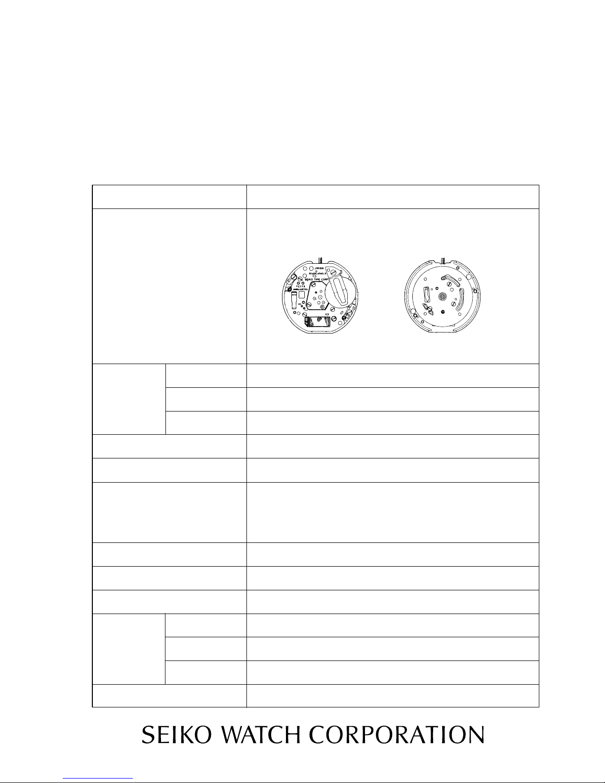
Cal. 7C17B
(×1.0)
Movement
Cal.No.
Movement size
(mm)
Outside diameter
Casing diameter
5.2 mm
2 hands
φ28.6 mm×27.0 mm between 3 o'clock and 9 o'clock sides
φ27.0 mm×25.4 mm between 3 o'clock and 9 o'clock sides
Time indication
Step motor (Load compensated driving pulse type)
Driving system
Electronic circuit reset switch
Additional mechanism
Monthly rate at normal temperature range : less than 15 secondsLoss/gain
Pattern cutting systemRegulation system
Use 10-second gate.Measuring gate by quartz tester
SEIKO SR43SW,Maxell SR43SW, U.C.C. 301, SONY EVEREADY 301 Battery type
Pressure 1.55V
approximately 5 yearsBattery life
7 jewels
Jewels
Battery
1/6
Height
[SPECIFICATIONS]
7C17B
Page 2

Disassembling procedures Figs.
Moebius A
SEIKO Watch Oil S-6
Normal Quantity
0022 493
Coil block screw
Antimagnetic shield plate
screw
0022 648
Battery clamp screw
1Case back
7Movement
8Bezel gasket
9Case (with bezel)
6Winding stem
(with crown)
2Case back gasket
4Casing clamp screw (2 pcs.)
0022 421
18
Minute wheel
0261 935
17
Setting wheel
2081 925
15
Dial sheet
0105 925
16
Hour wheel
0271 927
14
Dial sheet screw
(3 pcs.)
0022 257
13
Dial washer
0491 706
11Dial
10Hour and minute
PARTS CATALOGUE
12
Holding ring for dial
→Please see the remarks on the following pages.
5Casing clamp (2 pcs.)
0399 601
0022 421
Casing clamp screw
0022 257
Dial sheet screw
2/6
144
Lubricating: Types of Oil Oil quantity
Reassembling procedures Figs.
44
1
44
0866 544
hands
Train wheel bridge screw
Contact point spring
3
4281 514
Cal. 7C17B
→
→
Page 3

Cal. 7C17B
Eccentric dial pin
Tube for circuit block spacer A
Tube for circuit block spacer B
Tube for casing clamp screw
Setting lever pin
Tube for antimagnetic shield plate screw
Tube for traon wheel bridge
Casing clamp screw
Tube for coil block screw
3/6
29
Train wheel bridge
screw (2 pcs.)
30
Train wheel bridge
0125 925
31
Fourth wheel and
pinion 0241 927
32
Third wheel and
pinion 0231 935
33
Fifth wheel and
pinion 0701 925
34
Step rotor
4146 555
35
Train wheel setting
lever 0391 925
36
Setting lever spring
0388 925
37
Setting lever
0383 925
38
Yoke
0384 926
39
Winding stem
40
Clutch wheel
0282 926
41
Center wheel bridge
0122 925
42
Center wheel and
pinion 0221 938
20
Battery clamp
4225 555
24
Circuit block
4000 617
25
Circuit block spacer
4408 555
26
Battery connection (-)
4270 555
12 Holding ring for dial 0866 544 39
WWinding stem 0351 926
The types of these parts depend on the design of each model.
Refer to " SEIKO Casing Parts Catalogue" to choose corresponding parts.
Remarks:
19 Battery clamp screw
21
Battery (See the front page.)
22
Antimagnetic shield plate screw
0022 493
23
Antimagnetic shield plate
4259 506
0022 468
27 Coil block screw
0022 493
28 Coil block
4002 555
43
Rotor stator
4239 723
44
Main plate
0101 927
0022 493
Page 4

Use the universal movement holder for disassembling and reassembling.
5Casing clamp
●Setting position
Cross section
Bezel gasket
Casing clamp
Case middle
7
●When you remove the movement, push the movement
out of the back lid side to the bezel. When you build it
in, push it from the bezel side.
9
Bezel
Glass
3How to install the contact point spring
●Push the center of the contact spring, see the drawing,
until it touches winding stem. Be careful not transform
4/6
Center contact point spring
Cal. 7C17B
TECHNICAL GUIDE
●The explanation here is only for the particular points of Cal. 7C17B.
●For the repairing, checking and measuring procedures, refer to the "TECHNICAL GUIDE, GENERAL
I. REMARKS ON DISASSEMBLING AND REASSEMBLING
Install the casing clamp screw so that
this bent position is securely placed on
the step of the case middle.
Movement
the control point spring.
8
Bezel gasket
● Please refer to the illustration.
Case (with bezel)
●
•@Lubricate the pointed portion, see the illustration.
●
Do not lubricate bezel gasket.
INSTRUCTION".
Page 5

Cal. 7C17B
Eccentric dial pin
Eccentric dial pin
12
Holding ring for dial
Holding ring for dial
Protrusion
11Dial
Be sure to set the protrusion of the holding ring
for dial in place.
Movement
The foot of the dial has been tightened with
the eccentric dial pin. Turn the screw driver
right and tighten to attach, and turn left and
loosen to remove it.
Hole for dial leg
Hole for dial leg
31
Fourth wheel and pinion
5/6
38
Yoke
Setting lever spring
Train wheel setting lever
Setting lever
35
Train wheel setting lever
36
Setting lever spring
37
Setting lever
Setting lever spring
Setting lever
Yoke
Clutch wheel
40
Clutch wheel
*eccentric dial pin is non-supply parts, therefore
please do not lose it.
Page 6

Cal. 7C17B
41
Center wheel bridge
39
Winding stem
To prevent any crack onto the main plate, gently set the winding stem while turning it.
Lubricating
II. VALUE CHECKING
●Coil block resistance
2.0〜2.5kΩ
●Current consumption
For the whole of the movement:less than 1.30μA
For the circuit block alone: less than 0.20μA
Remarks:
When the current consumption exceeds the standard value for the whole of the movement but is less
than the standard value for the circuit block alone, overhaul and clean the movement parts and then
measure current consumption for the whole of the movement again. The driving pulse generated to
2006. June
6/6
compensate a heavy load that may apply on the gear train, etc. is considered to cause excessive current
consumption for the whole of the movement.
 Loading...