

Page 1

[SPECIFICATIONS]
Item
Cal. No.
Power generator
Rechargeable
battery
Monthly rate: less than 15 seconds (worn on the wrist at temperature
range between 5 and 35 ºC)
Nil
Use 10-second gate
M
ovement: less than 0.80 µA
Circuit block: less than 0.20 µA
Automatic generating system
TC 920 Titanium carbon lithium rechargeable battery
0.45V - 2.20V
From full charge to stoppage: approximately 6 months
6 jewels
1/22
PARTS LIST/ TECHNICAL GUIDE
KINETIC Cal. 5M54A
5M54A
Driving system
Additional function
Crown operation
Loss/Gain
Regulation system
Gate time for rate measurement
Current consumption
Power supply
Operating
voltage range
D u r a t io n o f
charge
Number of jewels
Interval of hands movements
Normal position
1st click position
2nd click position
Coil resistance
MON
TUE
WED
THU
FRI
SAT
SUN
• 3 hands (Hour/Minute/Second)
• Calendar Date (date dial)
Day (retrograde day indicator)
1 second
Stepping motor 2 pieces
•
Power reserve indicator (second hand)
• Energy depletion forewarning function
• Overcharge prevention function
• Electronic circuit reset function
• Day and date correction function
• Second hand stop function
Free
Day and date setting
• Deameter
Outside :
Ø 27.6 mm
Casing :
Ø 27.0 mm
• Height: 4.3
mm
Time setting (Hour and Minute)
5
M
5
4
A
Movement
Coil block: 1.70 - 2.10 K
Ω
G
enerating coil block: 280 - 380
Ω
Page 2

Cal. 5M54A
2/22
SPECIFICATIONS
10 seconds
20 seconds
30 seconds
Between 7 days and 1
month
Approx.
1 month
Approx. bet ween
4 and 6 months
Between
1 and 7 days
5 seconds
POWER R ESERVE
QUICK MOVEMENT OF
SECOND HAND
SEIKO KINETIC Cal. 5M54 is an analogue quar tz watch equipped with the Kinetic technology
developed by SEIKO. It generates the electric energy to power the watch, utilizing the movement of
your body, and stores it in the rechargeable battery, which requires no periodical replacement unlike
conventional button-type batteries.
1
. When the watch stops completely, or if you find
the second hand moving at two-second intervals,
swing the watch from side to side at a rate of
twice a second.
1. By swinging the watch
2. By using the KINETIC Energy Supplyer YT02A
2. 250 swings will reserve up to 1 day of power.
The second hand will start moving at one-second intervals.
Set the crown to the 5M position.
•
Make sure tha t the w atch i s correctly
positioned as it may affect the amount of
power generated.
•
The amount of power generated may vary
depending the models of the watch.
5M
Cal. 5M54A is equipped with a power reserve indicator. The current power reserve can be checked by
reading the posisiton of the second hand after pressing the button at the 2 o'clock position.
*
The second hand will resume normal movement after the indicated 5, 10, 20 or 30 seconds have
elapsed.
*
To allow easy reading of the second hand, press the button when the second hand is at the 12 o’clock
position.
*
It is recommended that the watch be swung further until 2 days of power is reserved. As a
guideline of recharging, additional 200 to 250 swings, about 450 to 500 swings in total will
reserve 2 days of power.
POWER RESERVE INDICATOR
POWER
RESERVE
NUMBER OF
SWINGS
250 450 ~ 500
1 DAY 2 DAYS
APPROX.
6 MONTHS
FULL
FEATURES
HOW TO CHARGE THE WATCH
Page 3

Cal. 5M54A
3/22
PARTS LIST
Disassembling procedures Figs. : 1 65
Reassembling procedures Figs. : 65 1
Lubricating: Types of oil
Watch Oil AO-3
Watch Oil AO-2
SEIKO Watch Oil S-6
Silicone oil 500,000 c.s.
Oil quantity
Normal quantity
Please see the remarks on the following pages.
Lubricating of some parts is shown in “ II. REMARKS ON DISASSEMBLING AND REASSEMBLING”.
1 CASE BACK
2 CASE BACK GASKE T
4 4281500
CONTACT POINT SPRING (*)
5 MOV EMENT
8 BUTTON SPRING
6 BUTTON SPRING CLIP
7 BUTTON
* The contac t point spring is not
assembled in models with s crew -loc k
type crown.
3
SET TING STEM
[CASING PARTS ASSEMBLY]
Page 4

26
27
28
0012354
DAY LEVER GUARD SC REW
0837 503
DAY LEVER GUARD
1002516
DAY WHEEL
1017503
DAY LEVER
1018504
DAY LEVER SPRIN G
0871502
DAY STAR WHEEL
0491735
DIAL WASH ER
0022247
DAY LEVER BRIDGE SCRE W
080 8514
DATE DIAL GUAR D
0878 B43
DATE DIAL
081066 0
DATE JUMPER
098 9660
INTERM EDIATE DAY CORREC TOR WHEEL
0737670
DATE CORREC TOR WHEEL
0962 670
INTERM EDIATE DATE CORR ECTOR WH EEL
0816670
DATE DRIVING WHEEL
0271607
HOUR WHE EL
DAY LEVER BRIDGE
086 6780
HOLDIN G RING FOR DI AL
12
13
14
15
16
17
18
19
20
21
22
23
24
25
SPACER FOR DI AL
11
440 856 4
440 855 9
29
X
II
I
II
II
I
I
I
I
I
I
I
V
VI
V
V
I
I
I
XI
X
XI
SEIKO
PREMIE
R
KINETIC
MON
TUE
WED
THU
FRI
SAT
SUN
RETRO GRAD E DAY HAND
DIAL
HOUR, MIN UTE AND S ECOND HA NDS
9
10
Cal. 5M54A
4/22
PARTS LIST
Please see the remarks on the following pages.
Lubricating of some parts is shown in “ II. REMARKS ON DISASSEMBLING AND REASSEMBLING”.
[CALENDAR MECHANISM/
DIAL AND HANDS SETTING]
Page 5

Cal. 5M54A
5/22
PARTS LIST
Please see the remarks on the following pages.
Lubricating of some parts is shown in “ II. REMARKS ON DISASSEMBLING AND REASSEMBLING”.
30 00224 90
OSCILL ATING WEIGHT SC REW
31 050 066 3
OSCILL ATING WEIGHT
32 10026 62
OSCILL ATING WEIGHT WHEEL
33 0022247
RECHARGEABLE BATT ERY CL AMP SC REW
3 4 4225519
RECHARGEABLE BATT ERY CL AMP
36 3023 44Z
RECHARGEABLE BATT ERY UNIT
37 0022247
CIRCUIT BLOCK COVER SCR EW
38 4457760
CIRCUIT BLOCK COVER
39 400 0732
CIRCUIT BLOCK
4 0 0022247
OSCILL ATING WEIGHT BRIDGE SCREW
41 4459500
CONDUCTIVE PLATE
42 0198662
OSCILL ATING WEIGHT BRIDGE
4 3 4002514
GENERATING COIL BLOCK
4 4 10026 60
INTERMEDIATE WHEEL FOR GENER ATING ROTOR
35 4216519
INSULATOR FOR RECHARGE ABLE BATTERY
4 5 4146518
GENERATING ROTOR
4 6 4239 519
GENERATING STATOR
47 0022247
COIL BLOC K SCRE W
4 8 4002516
COIL BLOC K
[AUTOMATIC GENERATING
MECHANISM/ELECTRONIC
CIRCUIT]
Page 6

Cal. 5M54A
6/22
PARTS LIST
Please see the remarks on the following pages.
Lubricating of some parts is shown in “ II. REMARKS ON DISASSEMBLING AND REASSEMBLING”.
50 0125661
TRAIN WHEEL BRIDGE
51 0391660
TRAIN WHEEL SETTING LEVER
52 4271515
RECHARGEABLE BATT ERY
CONNECTION (+)
53 0241667
FOURTH WHEEL AND PINION
55 0701670
FI FTH W HEEL AND PINION
56 4146531
STEP ROTOR
57 0261670
MINUTE W HEEL
58 0281670
SETTING WH EEL
59 445 0730
SWITCH LEVER
6 0 0384661
YOKE
61 0383662
SETTING LEVER
62 4239 518
ROTOR STATOR
3 SE TTING STEM
6 3 02826 72
CLUTCH WHEEL
6 4 0221667
CENTER WHEEL AND PINION
65 01006564 ( FOR STANDARD CASE TYPE)
010065 9 (FO R ONE-PIECE CASE T YPE)
MAIN PL ATE
5 4 0231530
THIRD WHEEL AND PINION
4 9 0022247
TRAIN WHEEL BRIDGE SCREW
[GEAR TRAIN MECHANISM/
SETTING MECHANISM]
Page 7

Cal. 5M54A
7/22
PARTS LIST
l
How to find the correct parts, if not determined by 4 digit caliber number
Following parts are determined based on the design of watches, such as hands height, dial color,
and design of cases. Please refer to the SEIKO WATCH PARTS CATALOGUE in order to choose
corresponding parts.
Remarks
4 CONTACT POINT SPRING 4281500
The contact point spring is not assembled in models with screw-lock type crown.
12 HOLDING RING FOR DIAL 0866780
23 DATE DIAL
Part code Position of crown
Position of calendar
frame
Color of figure
Color of back
ground
0878 B42 3 o'clock 3 o'clock White Black
0878 B43 3 o'clock 3 o'clock Black White
0878 B25 3 o'clock 6 o'clock White Black
0878 B26 3 o'clock 6 o'clock Black White
3 SETTING STEM 0351653
Page 8
Cal. 5M54A
8/22
PARTS LIST
l
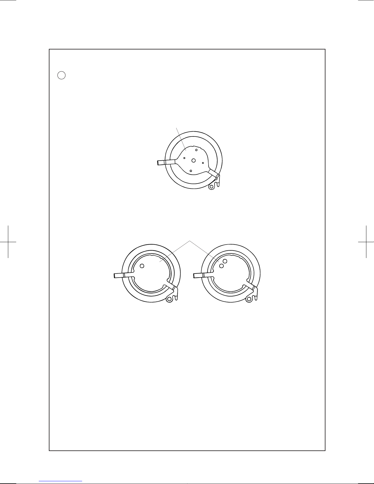
How to discriminate resembled parts
36 RECHARGEABLE BATTERY UNIT
Though the R
ECHARGEABLE BATTERY UNIT for Cal. 5M54 and 5M6 Series is of a completely
different type from the C
APACITOR UNIT for Cal. 5M4 Series, they have a close resemblance in
shape. They can be discriminated by the shapes of their minus lead terminals as illustrated below.
When repairing the R
ECHARGEABLE BATTERY UNIT, check the shape of its minus lead terminal to
make sure you are using a R
ECHARGEABLE BATTERY UNIT properly.
Minus lead terminal
[RECHARGEABLE BATTERY UNIT for Cal. 5M54 and 5M6 Series ]
Part code: 302344Z
Marking on the battery:
maxell TC920
[CA
PACITOR UNIT for Cal. 5M4 Series ]
Part code: 3029113
Marking on the capacitor: SII SL920
Minus lead terminal
Current type
Old type
Page 9
Cal. 5M54A
9/22
PARTS LIST
0022247
• DAY LEVER BRIDG E SCRE W (3 PCS.)
• RECHARGEABLE BATTERY CLAMP SCRE W (2 PC S.)
• CIRCUIT BLOCK COVER SCREW (2 PCS.)
• OSCILLATING WEIGHT BRIDGE SCREW (2 PCS.)
• COIL BLOCK SCREW (1 PC.)
• TRAIN WHEEL BRIDGE SCREW (1 PC.)
0022490
• OSCILLATING WEIGHT SCRE W (1 PC.)
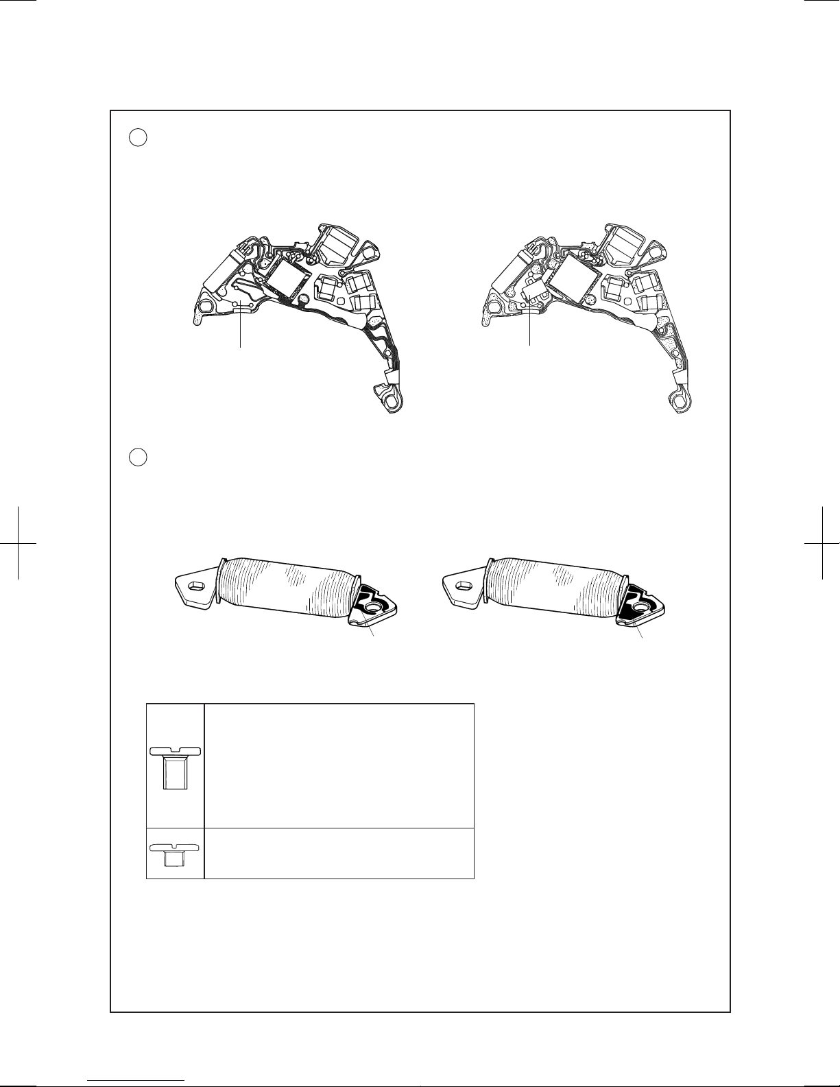
39 CIRCUIT BLOCK 4000732
The C
IRCUIT BLOCK for Cal. 5M54 and 5M6 Series and that for Cal. 5M4 Series have a close resemblance
in shape. They can be discriminated in the point that the C
IRCUIT BLOCK for Cal. 5M54 and 5M6
Series has no diode element unlike that for Cal. 5M4 Series. When repairing the C
IRCUIT BLOCK,
check that it has no diode element to make sure you are using the proper one.
Having no diode element Diode element
[ CIRCUIT BLOCK for Cal. 5M54 and 5M6 Series ] [ CIRCUIT BLOCK for Cal. 5M4 Series ]
43 GENERATING COIL BLOCK 4002514
The G
ENERATING COIL BLOCK for Cal. 5M54 and 5M6 Series and that for Cal. 5M4 Series have a close
resemblance in shape. They can be discriminated by the size of the pattern on the lead terminal. If
the G
ENERATING COIL BLOCK for Cal. 5M4 Series is assembled by mistake, no electricity will be
generated. When repairing the G
ENERATING COIL BLOCK, check the size of the pattern on the lead
terminal to make sure you are using the proper one.
Smaller pattern Larger pattern
[ GENERATING COIL BLOCK for Cal. 5M54 and 5M6 Series ] [ GENERATING COIL BLOCK for Cal. 5M4 Series
]
Page 10
Cal. 5M54A
10/22
PARTS LIST
l
Tools and consumables required for disassembling/reassembling
• Movement holder
Universal movement holder (S-682)
• Watch oils
SEIKO watch grease (S-6) and watch oils (AO-3 and AO-2)
S-6
AO-2
AO-3
Page 11
Cal. 5M54A
11/22
TECHNICAL GUIDE
REMARKS ON DISSASEMBLING AND REASSEMBLING THE MOVEMENT
l
How to remove the SETTING STEM before dismantling the movement
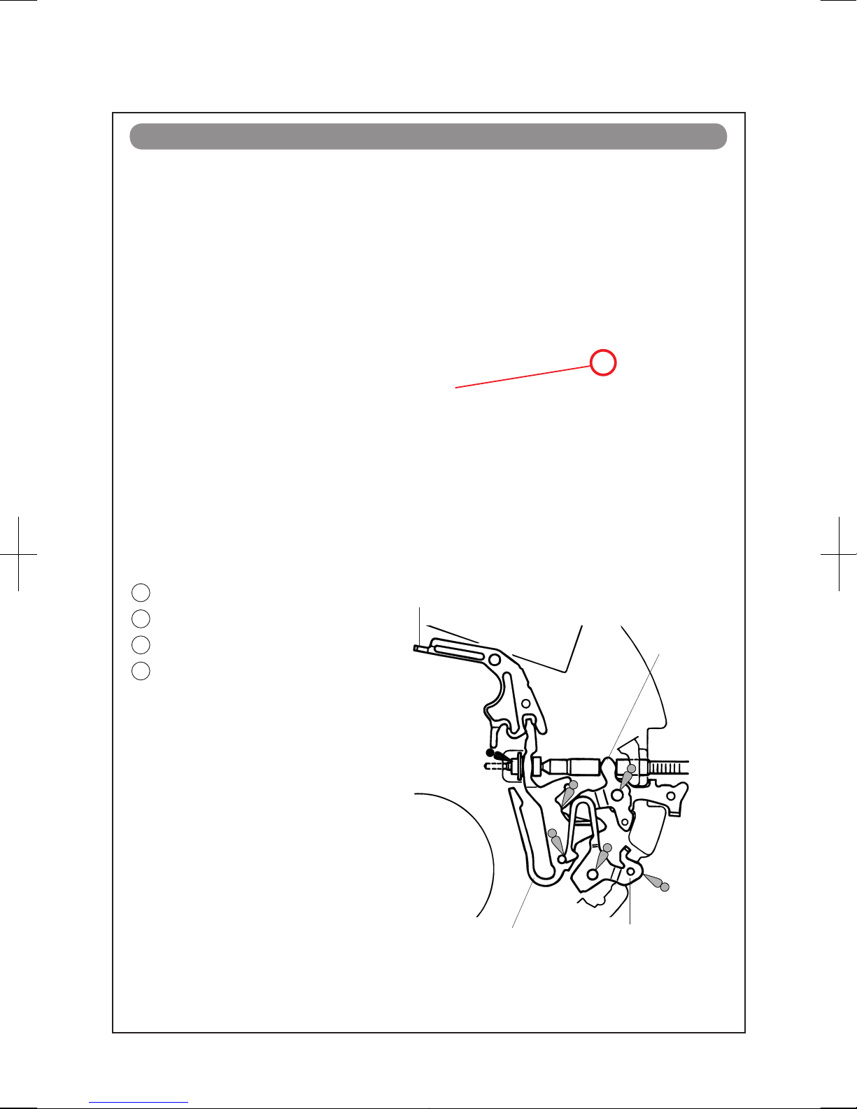
51 TRAIN WHEEL SETTING LEVER
59 SWITCH LEVER
60 YOKE
61 SET TING LEVER
• Setting position and lubricating
Refer to the illustration at right.
Train wheel setting lever
Setting lever
Switch lever
Yoke
l
SETTING MECHANISM
Crown position: 1st click position
Push the SETTING LEVER gently (refer to the picture on
the right) in order to disengage it from the SETTING
S
TEM. Then pull out the crown with stem completely.
Push here
Page 12
Cal. 5M54A
12/22
TECHNICAL GUIDE
l
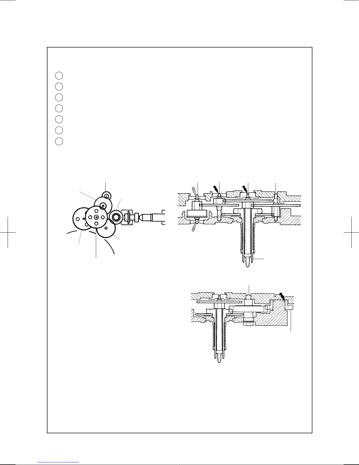
Gear train mechanism - train wheels, setting position and lubricating
53 FOURTH WHEEL AND PINION
54 THIRD WHEEL AND PINION
55 FIFTH WHEEL AND PINION
56 STEP ROTOR
57 MINUTE WHEEL
58 SET TING WHEEL
• Setting position and lubricating
Refer to the illustrations below for the setting position and lubrication of the respective wheels.
Fifth wheel
and pinion
Step rotor
Setting wheel
Fourth wheel
and pinion
Minute wheel
Third wheel
and pinion
Center wheel
and pinion
Step rotor
Fifth wheel
and pinion
Fourth wheel
and pinion
Third wheel
and pinion
64 CENTER WHEEL AND PINION
Note: Be sure to observe the position, type of
oil and quantity of lubrication specified
in the illustration.
Minute wheel
Setting wheel
Page 13
Cal. 5M54A
13/22
TECHNICAL GUIDE
l
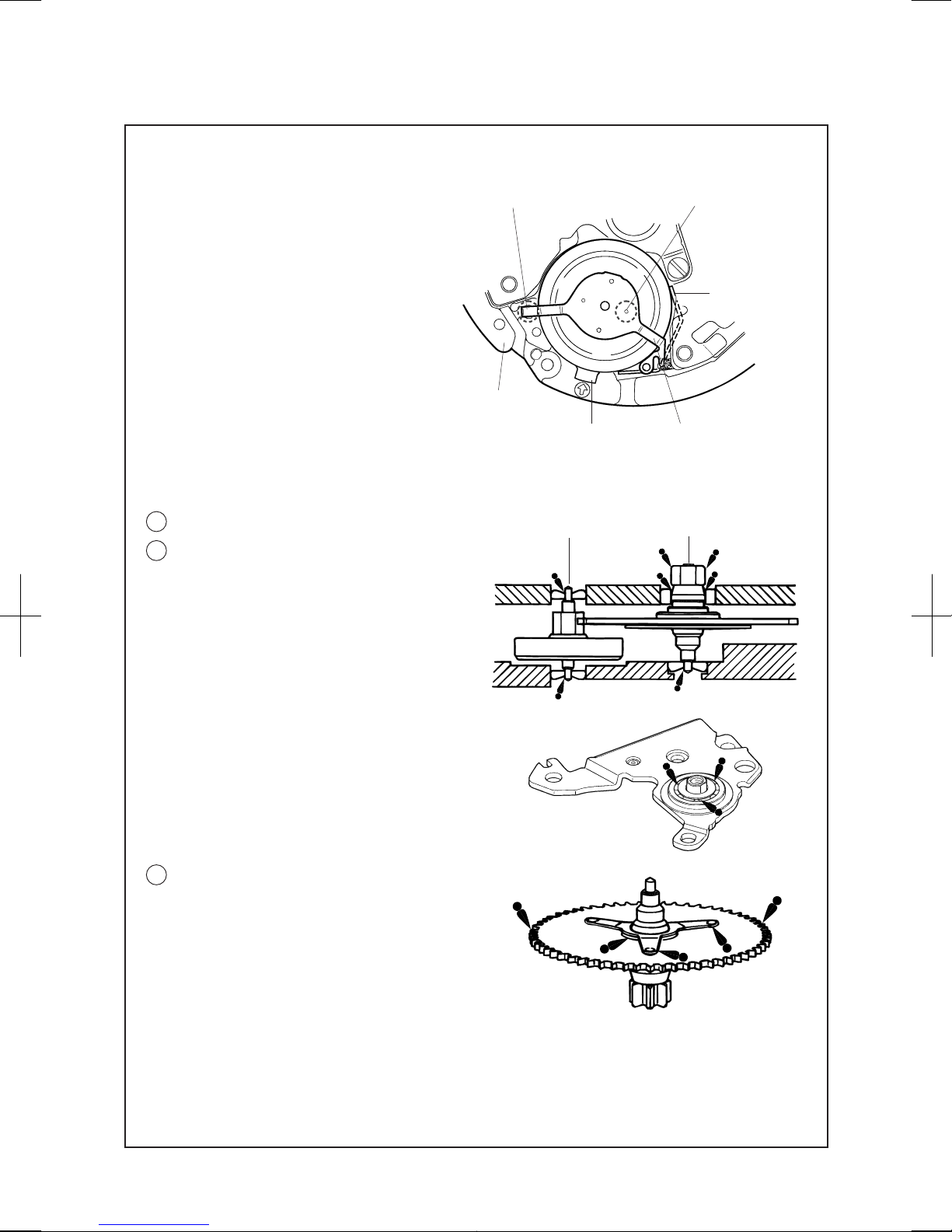
Automatic generating mechanism
• How to remove
Insert the tip of tweezers into the “C”
portion gap in the illustration at right, and
pry up the R
ECHARGEABLE BATTERY
UNIT to remove it.
•
How to install
Set the “A” portion of the minus lead
terminal to the hole of the M
AIN PLATE,
and push the “B” portion down vertically
so that the R
ECHARGEABLE BATTERY
UNIT is well seated in position.
Note: T
ake utmost care not to short-circuit
the (+) and (-) terminals, as this will
deteriorate the battery unit.
“A” portion
Main plate
メCメ portion Minus lead terminal
Rechargeable
battery plus
terminal
メBメ portion
40 OSCILLATING WEIGHT BRIDGE SCREW
42 OSCILLATING WEIGHT BRIDGE
Before tightening the O
SCILLATING WEIGHT
bridge screw, check that the upper pivot of the
G
ENERATING ROTOR is inserted properly into
the pivot jewel.
Be sure to lubricate the upper and lower pivots
of G
ENERATING ROTOR and INTERMEDIATE
WHEEL FOR GENERATING ROTOR with the
proper oil in the quantit y specified in the
illustration.
Lubricate the ball-bearing of the O
SCILLATING
WEIGHT BRIDGE as shown in the illustration
at right.
Intermediate wheel for
generating rotor
Generating rotor
44 INTERMEDIATE WHEEL FOR GENERATING ROTOR
• Lubricating
Refer to the illustration at right.
Note: B
e sure to observe the position, type of oil
and quantity of the lubrication specified
in the illustration.
• Lubricating
Page 14
Cal. 5M54A
14/22
TECHNICAL GUIDE
REMARKS ON DE-CASING/CASING/DIAL AND HAND SETTING
l
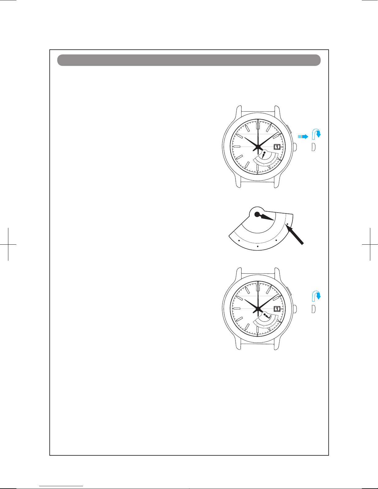
How to set the retrograde day hand at the first day position
MON
TUE
WED
THU
FRI
SAT
SUN
Make sure the DAY LEVER and the DAY STAR WHEEL are at the 1st day position by listening the sound
when changing the day.
1
. Turn the crown clockwise at the first click position until
you hear the unique sound when changing from 7th
day to 1st day.
2
. Install the hand pointing to the 1st day ( MON)
position.
MON
TUE
WED
THU
FRI
SAT
SUN
3. Make sure the day changes correctly and smoothly
by turning the crown at the first click position.
MON
TUE
WED
THU
FRI
SAT
SUN
Page 15
Cal. 5M54A
15/22
TECHNICAL GUIDE
l
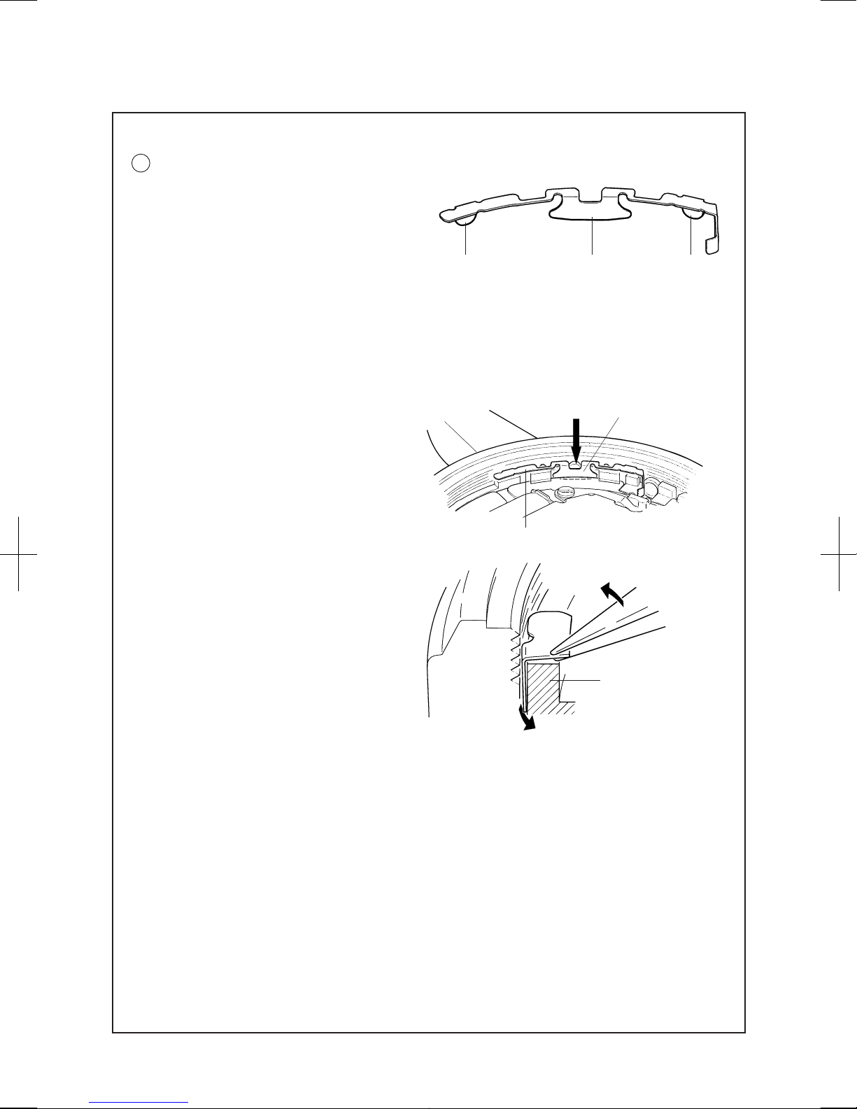
How to remove/install the contact point spring
4 CONTACT POINT SPRING
The C
ONTACT POINT SPRING has three hooking
portions bent downward. It is fixed by inserting
the hooking portion “A” into a gap between the
M
AIN PLATE and H
OLDING RING FOR DIAL and
inserting “B” and “C” into a gap between the
H
OLDING RING FOR DIAL and CASE.
“B”
“A”
“C”
* Before disassembling or assembling the CONTACT POINT SPRING, be sure to remove the
SETTING STEM.
• How to remove
Insert the tip of tweezers into the gaps between the hooking portions “A”, “B” and “C “ of the
C
ONTACT POINT SPRING and H
OLDING RING FOR DIAL, and pry up the CONTACT POINT SPRING
slowly to remove it.
•
How to install
1) Push the hooking portion “A” in the
direction of the arrow in the illustration
at right to insert it into a gap between the
M
AIN PLATE and H
OLDING RING FOR
DIAL.
2
) Insert the hooking portions “B” and “C”
into a gap between the H
OLDING RING
FOR DIAL and CASE.
I
n doing so, the installation will be
made more easily by pushing down the
C
ONTACT POINT SPRING while slightly
lifting it up so that the tips of the hooking
portions “B” and “C” are tilted toward the
H
OLDING RING FOR DIAL.
Note: W
hen removing or insta lling t he
CONTACT POINT SPRING, take utmost
care not to deform its shape.
Contact point spring
Hooking portion メAメ
Case
Holding ring for dial
Page 16
Cal. 5M54A
16/22
TECHNICAL GUIDE
REMARKS ON INSPECTION AND MEASUREMENT
l
Value checking
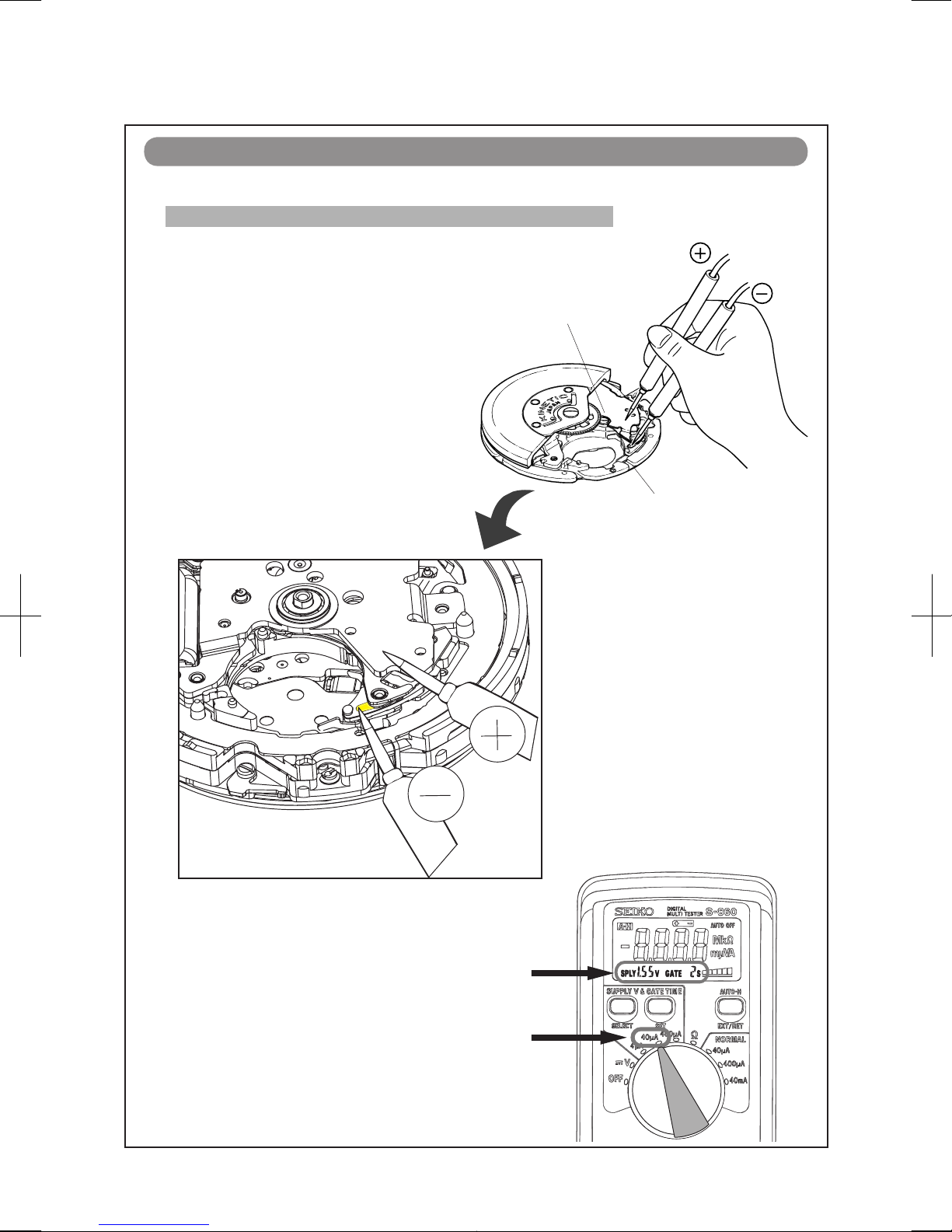
How to measure the current consumption for the whole movement
1. Remove the RECHARGEABLE BATTERY
UNIT
(36), an I
NSULATOR (35) and the
BATTERY CLAMP WITH SCREWS (33) and
(34), then reassemble the O
SCILLATING
WEIGHT WHEEL (32) and O
SCILLATING
WEIGHT (31) and tighten the SCREW (30)
temporary in order to make the movement
ready for measurement.
2
. Connect the (-) probe of the tester to the
input terminal (-) of the C
IRCUIT BLOCK
and (+) probe to the other metal part of
the movement, such as C
IRCUIT BLOCK
COVER.
“a” portion
Circuit block cover
* When measuring the current consumption using
the SEIKO digital multi-tester ( S - 8 60), use the
range of 40 μ A o
f SUPPLY V (= 1.55 V) &
GATE TIME (2 S)
Page 17
Cal. 5M54A
17/22
TECHNICAL GUIDE
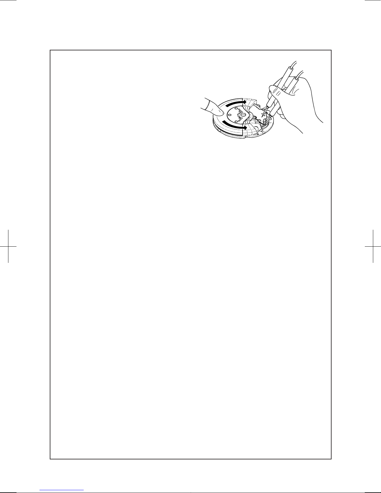
3. Swing the OSCILLATING WEIGHT as the illustration
for more than three seconds so that the movement
detects the electricity generation and it turns to the
normal hand movement mode.
Note: When swinging the O
SCILLATING WEIGHT, take
care so as not to touch the probes of the tester.
4
. Wait for more than 10 seconds until a stable measurement is obtained, and then read the
measurement.
5
. Make sure the read value is less than 0.80 μA.
Page 18
Cal. 5M54A
18/22
TECHNICAL GUIDE
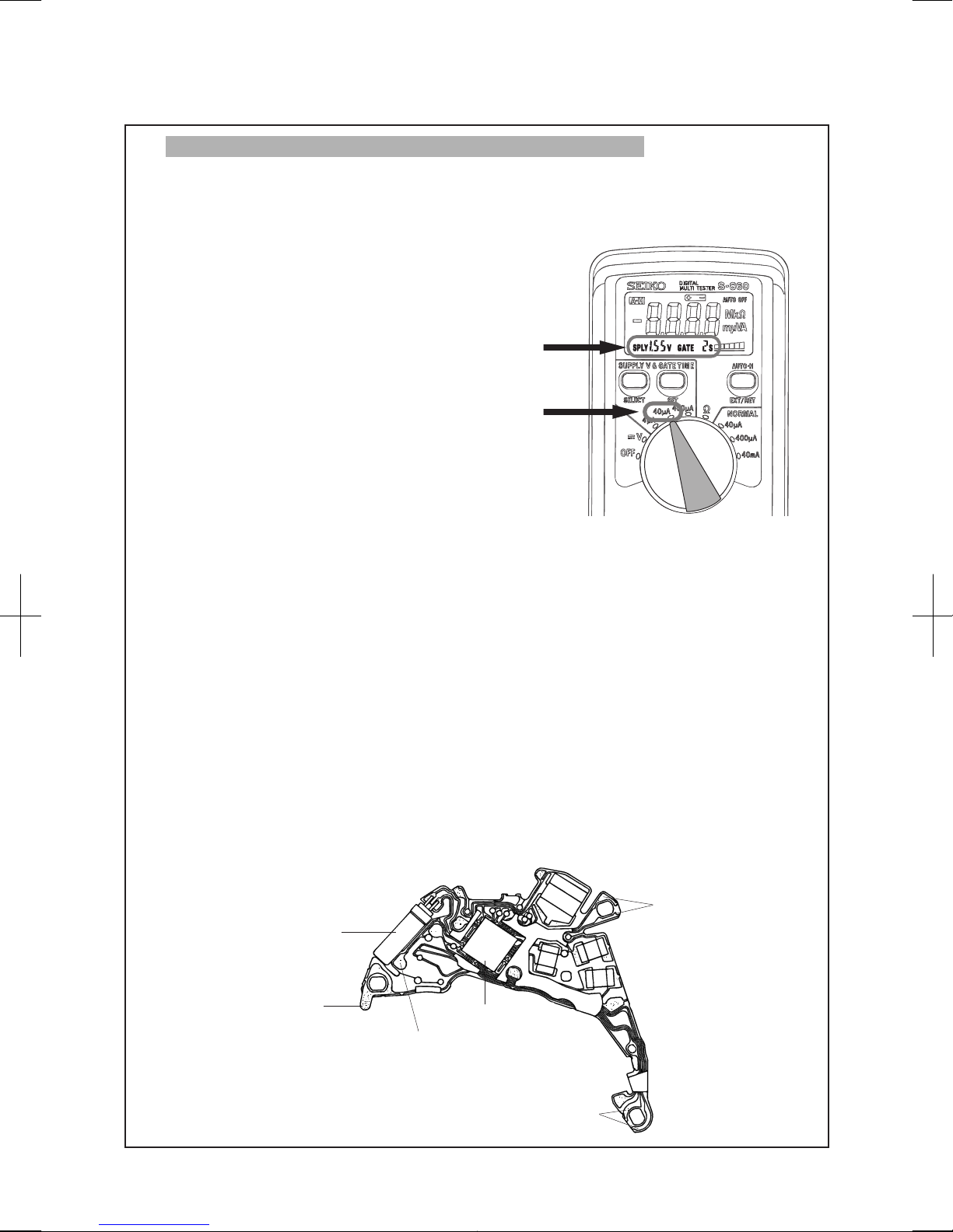
How to measure the current consumption for the CIRCUIT BLOCK alone
[Structure of the CIRCUIT BLOCK]
Coil output terminal
Crystal unit
Input terminal ( - )
C-MOS-IC
Input terminal (+)
Automatic generating
input terminal
1. To measure the current consumption for the CIRCUIT BLOCK alone, connect each probe to the
appropriate positive (+) or negative (-) input terminal of the C
IRCUIT BLOCK (please refer to
“Structure of the circuit block” below).
*
When measuring the current consumption using
the SEIKO digital multi-tester ( S - 8 60), use the
range of
40 μ A o
f SUPPLY V (= 1.55 V) &
GATE TIME (2 S)
2. In order to turn the mode of the C-MOS-IC into the normal hand movement mode, short-circuit
it by touching “A” portion and the input terminal (-) with tweezers for more than three seconds.
*
When measuring the current consumption for the CIRCUIT BLOCK alone, be careful not to damage
or deform the pattern of the CIRCUIT BLOCK.
3
. Read the measurement when a stable measurement is obtained.
4. Make sure the read value is less than 0.20 μA.
Page 19
Cal. 5M54A
19/22
TECHNICAL GUIDE
l
Value checking
• Coil resistance (coil blocks)
Check the resistance of each C
OIL BLOCK if they are within the range in the following table.
COIL BLOCK
4002516
1.7 KΩ - 2.1 K
Ω
GE
NERATING COIL
BLOCK
4002514
280 Ω - 380
Ω
l
Function check
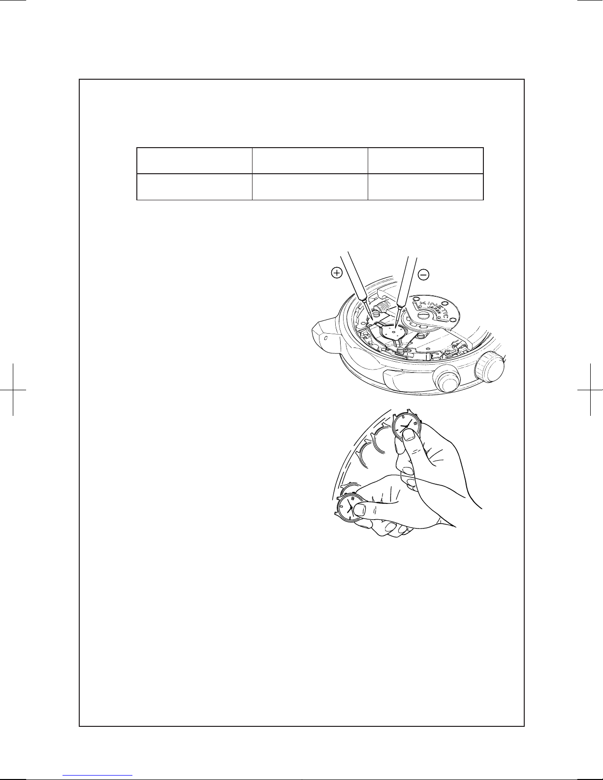
• Checking the automatic generating system
1. Apply the probes of the tester as shown in
the illustration, and measure the voltage of
the R
ECHARGEABLE BATTERY. The obtained
voltage is called the “initial voltage”.
N
otes:
* When applying the minus probe of the
tester to the R
ECHARGEABLE BATTERY,
take care not to short-circuit the lead
terminal (-) and the R
ECHARGEABLE
BATTERY CLAMP.
*
If a short-circuit has occurred, leave
the watch untouched for more than 10
minutes, and measure the voltage again,
checking that a stable measurement is
obtained.
2. Close the case back tentatively, and swing the
watch from side to side 200 times at a rate
of 2 to 3 swings a second, making an arc of
approximately 20 cm.
Page 20
Cal. 5M54A
20/22
TECHNICAL GUIDE
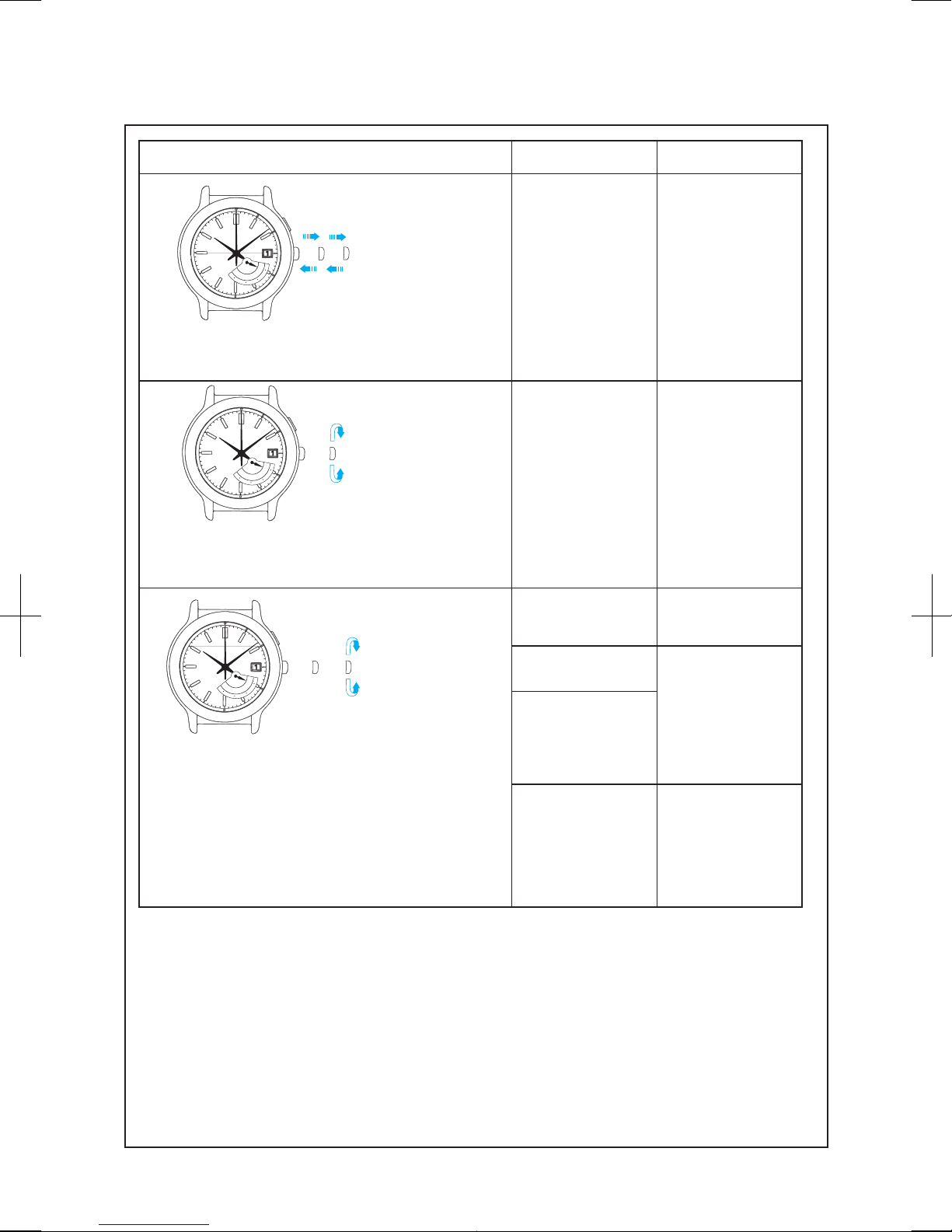
Operation Function Checkpoint
MON
TUE
WED
THU
FRI
SAT
SUN
Pull out the
crown to the 2nd
click and push it
back in to the
normal
position. Repeat
the same several
times.
Setting mechanism switching the
function of the time
setting
Make sure that it has
a click at each
position and the
stem is not pulled
off.
MON
TUE
WED
THU
FRI
SAT
SUN
Pull out the
crown to the 1st
click, then turn it.
Calendar
mechanism correcting the date
(and day), if
available
Make sure that the
date (and day)
changes smoothly.
MON
TUE
WED
THU
FRI
SAT
SUN
Pull out the
crown to the 2nd
click*, then turn
it.
Second hand stop
function (if
available)
Make sure that the
second hand stops
when the crown is
Setting mechanism hour and minute
Make sure that the
hour and minute
hands move
smoothly (without
touching each other
or touching the
surface of the dial or
inside of the glass).
Hands installation
Calendar
mechanism - date
change
Make sure that the
date changes when
the hour and minute
hands pass around
midnight.
•
If the watch does not have calendar mechanism, check thesame with the crown at the 1st click
position.
Page 21
Cal. 5M54A
21/22
TECHNICAL GUIDE
l
Water resistance test
l
Ac
curacy test
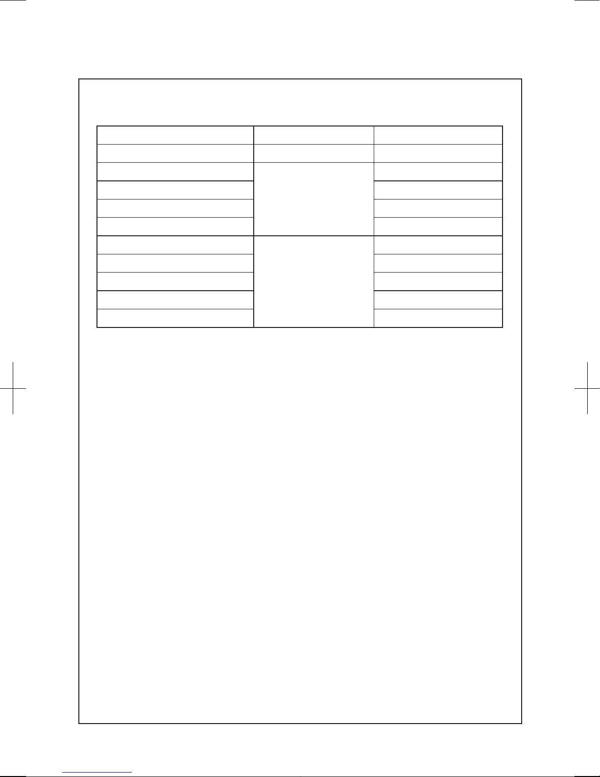
Check the water resistance according to the designated specification of the watch.
Measure the rate and make sure the value shows within ±0.50 s/d.
Use 10 seconds gate of the tester.
Marking on the case back Test method Applied pressure
WATER RESISTANT (WATER RESIST) Air overpressure test 3 BAR
WATER RESIST 5BAR
Water overpressure test
and condensation test
5 BAR
WATER RESIST 10BAR 10 BAR
WATER RESIST 15BAR 15 BAR
WATER RESIST 20BAR 20 BAR
SCUBA DIVER’S (AIR DIVER’S) 150 m
Water-tightness and water
overpressure test and
condensation tests before /
after water overpressure
test
18.75 BAR = 150 (m) times 0.125
SCUBA DIVER’S (AIR DIVER’S) 200 m 25 BAR = 200 (m) times 0.125
He-GAS DIVER’S 300 m 37.5 BAR = 300 (m) times 0.125
He-GAS DIVER’S 600 m 75 BAR = 600 (m) times 0.125
He-GAS DIVER’S 1000 m 125 BAR = 1000 (m) times 0.125
Page 22
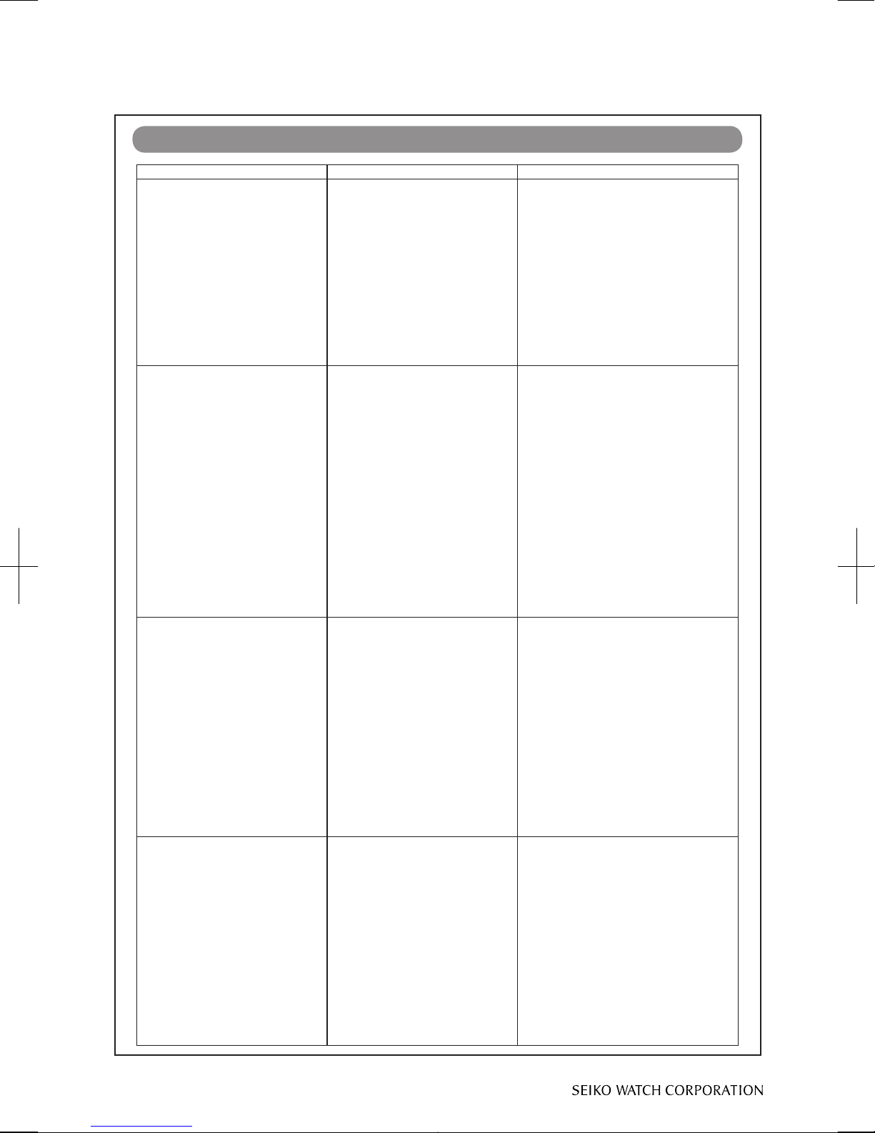
Problems Possible causes Methods of repair and checking
The O
SCILLATING WEIGHT
rotates at an abnormally high
rate, and no charging is made.
1) The COIL of the
G
ENERATING COIL BLOCK is
broken.
2) The pivot of the
G
ENERATING ROTOR is
broken. (The pinion of the
G
ENERATING ROTOR and the
gear of the I
NTERMEDIATE
WHEEL FOR GENERATING
ROTOR are out of mesh.)
1) Check the resistance of the
G
ENERATING COIL BLOCK.
Replace the G
ENERATING COIL
BLOCK if the COIL is broken.
2) Remove the broken piece of the
G
ENERATING ROTOR, and replace
and lubricate the G
ENERATING
ROTOR. (Overhaul and clean if
necessary.)
The O
SCILLATING WEIGHT
will not rotate.
1) The gear of the
OSCILLATING WEIGHT and
the pinion of the
I
NTERMEDIATE WHEEL FOR
GENERATING ROTOR
are out
of mesh.
2) The pivot of the
G
ENERATING ROTOR is
broken. (The pinion of the
G
ENERATING ROTOR and the
gear of the
INTERMEDIATE
WHEEL FOR GENERATING
ROTOR engage with each
other.)
1) If the gear of the O
SCILLATING
WEIGHT and the pinion of the
I
NTERMEDIATE WHEEL FOR
GENERATING ROTOR
are intact,
reassemble them to the movement.
2) Remove the broken piece of the
G
ENERATING ROTOR, and replace
and lubricate the G
ENERATING
ROTOR. (Overhaul and clean if
necessary.)
The current consumption for
the whole of the movement
exceeds the standard value.
1) When the measurement is
made, the IC is still in the
quick start mode. (When the
current consumption
m
easures about 200µA, it is
likely that the IC is in the quick
start mode.)
2) The load applied on the
gear train, etc. has increased,
and the driving pulse to
compensate it has been
generated.
1) After connecting the tester, move
the O
SCILLATING WEIGHT more
quickly for a longer period of time,
and then, make the measurement
again.
2) If the current consumption for
the C
IRCUIT BLOCK alone is within
the standard value range, overhaul
and clean the movement parts, and
then, make the measurement again.
The current consumption for
the C
IRCUIT BLOCK alone
exceeds the standard value.
1) The light from outside the
movement is affecting the
measurement.
2) When the measurement is
made, the IC is still in the
quick start mode. (When the
current consumption
m
easures about 200µA, it is
likely that the IC is in the quick
start mode.)
3) The IC is out of order.
1) Shut out the light, and make the
measurement again.
2) Switch the IC to the normal
mode, and make the measurement
again.
3) Replace the C
IRCUIT BLOCK.
Cal. 5M54A
22/22
TECHNICAL GUIDE
Copyright©2008 by
TROUBLESHOOTING
 Loading...