

Page 1
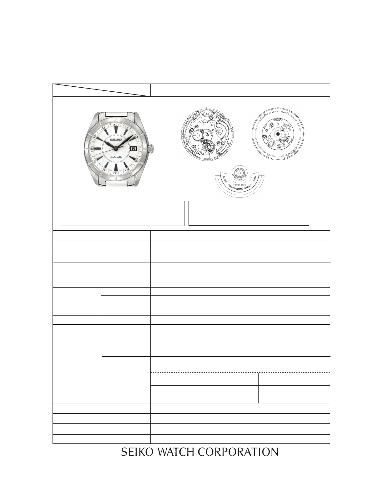
PARTS LIST / TECHNICAL GUIDE
Automatic Cal. 4
R35A
[SPECIFICATIONS]
1/18
Item
Cal. No.
4R35A
Driving system
Additional function
Crown operation
Loss/Gain
Regulation system
Number of jewels
Normal position
1st click position
2nd click position
Lift angle of the escapment
Vibration per hour
Power reserve
Time indication
•
3 hands (hour, minute and second hands)
• Date indication
• Diameter Outside: Ø 27.4 mm
Casing: Ø 27.0 mm
• Height: 5.25 mm
Movement size
Automatic winding with manual winding mechanism
• 3 hands (Hour, Minute and Small Second hands)
• Date indicator
• Date correction function
• Second hand stop function
Date setting (counterclockwise)
Time setting (Hour and minute)
Manual winding (clockwise only)
21,
600 (6 beats per second)
Between + 45 and - 35 seconds
Mainspring
wind up status
Testing positions
(Isochronism
fault: T24-T0)
± 30 s/d
Measurement
(daily rate in
seconds:s/d)
Dial upward:
T0 (CH)
Daily rate worn
on the wrist at
t e mp er a t ur e range between
5 °C and 35 °C)
St an d a r d r a te
for measurement
6 o’clock
at the top
Dial upward :
T24 (CH)
9 o’clock
at the top
A
fter 24 hours
from fully wind
up
Fully wind up
± 30 s/d
23 jewels
ETACHRON system
F
rom fully wound to stoppage: Approximately 41 hours
52 °
Second hand stop
± 20 s/d
± 30 s/d
Page 2

SPECIFICATIONS
2/18
Cal. 4R35A
FEATURES
CHARACTERISTICS OF A MECHANICAL WATCH
1. This mechanical watch operates using power obtained from a mainspring.
2. While loss/gain of a quartz watch is indicated by a monthly or annual rate, accuracy of a
mechanical watch is normally indicated by a daily rate (loss/gain per day).
3. Normal usage accuracy of a mechanical watch varies according to conditions of use (time
period that the watch is worn on the wrist, temperature environment, hand movement, and
winding state of the mainspring).
4. When the watch is affected by strong magnetism, it temporarily gains or loses time. If the
watch encounters a strong magnetic field, the parts of the watch may be magnetized. In this
case, repairs such as removal of magnetism are required.
SEIKO Automatic mechanical Cal. 4R35A is developed based on Cal. 7S series and Cal. 6R series design
with two specifications as follows :
1. M
anual winding function.
2. Second hand stop function for time setting (2nd click position of the crown)
Page 3
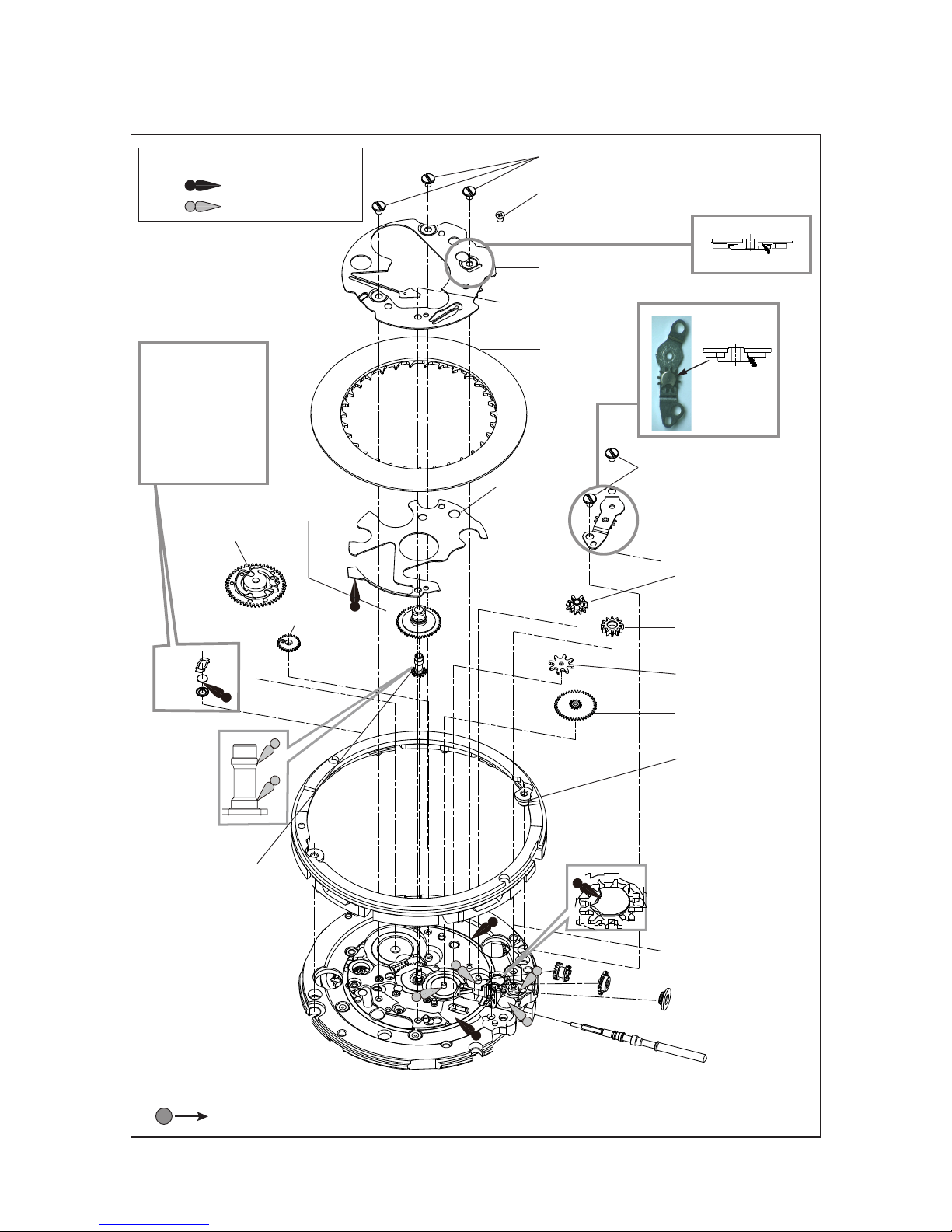
PARTS LIST
Cal. 4R35A
3/18
Please refer to the following pages.
2 DATE DISK GUARD SCREW A (3pcs.)
0012 354
4 DATE DISK GUARD
0808 060
3 DATE DISK GUARD SCREW B
0016 705
5 DATE DISK
6
DATE JUMPER
0810 030
7 GUARD SCREW OF
INTERMEDIATE WHEEL FOR
DATE SETTING
0012 354
8 GUARD OF INTERMEDIATE
WHEEL FOR DATE SETTING
0836 010
9 INTERMEDIATE WHEEL
FOR DATE SETTING E
0962 025
q; INTERMEDIATE WHEEL
FOR
DATE SETTING C
0962 024
qa DATE SETTING WHEEL
0737
300
qg MINUTE WHEEL
0261 006
qj CLUTCH WHEEL
0282 040
qk WINDING PINION
0283 020
ql CALENDAR
CORRECTOR
1ST
INTERMEDIATE
WHEEL 0962 164
qh
DIAL HOLDING SPACER
4408 ***
qsHOUR
WHEEL
0271 483
qd DA
TE DRIVING WHEEL
0802 300
qf
INTERMDIATE
WHEEL FOR
DATE DRIVING
0817 300
CANNON PINION
0225 005
(Disassemble after
CENTERWHEEL)
td
qj
qk
ql
Lubricating: Types of oil
AO-3 (Moevius A)
SEIKO Watch Oil S-6
S-6
S-6
Page 4
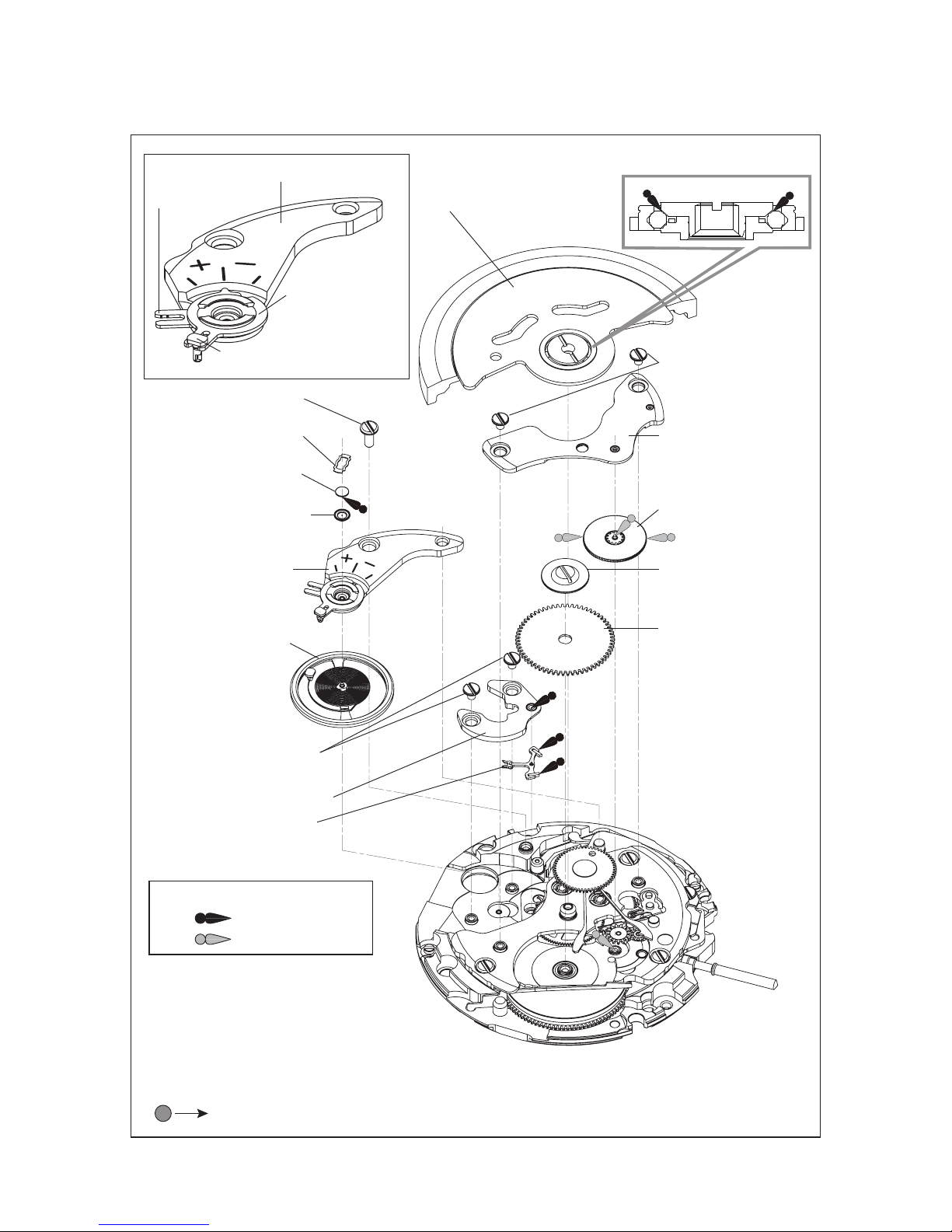
Cal. 4R35A
PARTS LIST
4/18
Please refer to the following pages.
1 OSCILLATING WEIGHT 0509***
wf-4 STUD SUPPORT
0345021
wf-1 BALANCE COCK 0171116
wf-2
REGULATOR
0341020
wf-3 REGULATOR PIN 0033364
wj PALLET BRIDGE 0161300
wk PALLET FORK 0301009
wl AUTOMATIC TRAIN
BRIDGE SCREW (2 PCS.)
0012354
e; AUTOMATIC TRAIN
BRIDGE 0191032
ea 2ND REDUCTION WHEEL
0514010
es RACHET WHEEL SCREW
0012919
ed RACHET WHEEL
0285051
wf
BALANCE COCK WITH
REGULATOR
0171353
wd BALANCE COCK SCREW
0012420
wa
SHOCK ABSORBING CAP
JEWEL
0011220
ws
HOLE JEWEL FRAME FOR
SHOCK ABSORBER 0014295
wg
BALANCE COMPLETE
0310046
wh
PALLET BRIDGE SCREW
0012354
w;
SHOCK ABSORBING SPRING
0014577
Lubricating: Types of oil
AO-3 (Moevius A)
SEIKO Watch Oil S-6
Page 5

PARTS LIST
Cal. 4R35A
5/18
Please refer to the following pages.
ef BARREL AND TRAIN WHEEL BRIDGE SCREW (3PCS)
0012420
r; LOWER BRIDGE FOR CROWN
WHEEL AND REDUCTION WHEEL
0436164
ej 1ST
REDUCTION
WHEEL
0511010
eh BARREL AND TRAIN
WHEEL BRIDGE 0014348
el LOWER BRIDGE FOR CROWN WHEEL
AND REDUCTION WHEEL SCREW
0012354
eg SLIDING CROWN WHEEL SPRING 0363156
ra 1ST
REDUCTION
WHEEL HOLDER
0836020
ek PAWL LEVER
0831077
rj THIRD
WHEEL 0231070
rk CLICK
0381004
rl BARREL COMPLETE 0201267
rs HOLD
SPRING FOR ESCAPE WHEEL
0015703
rd CAP JEWEL FOR ESCAPE WHEEL
0011221
rf HOLD SPRING FOR THIRD WHEEL
0015703
rg CENTER WHEEL BRIDGE SCREW
0012354
rh CENTER
WHEEL BRIDGE
0122302
rs
rd
rf
rg
Lubricating: Types of oil
AO-3 (Moevius A)
SEIKO Watch Oil S-6
Page 6

Cal. 4R35A
PARTS LIST
6/18
Please refer to the following pages.
t; CENTER WHEEL BRIDGE SCREW
0012354
tf
CENTER WHEEL
(Disassemble after CANNON PINION)
ta
CENTER WHEEL BRIDGE
0122302
ts
ESCAPE WHEEL
0251300
tg SETTING LEVER JUMPER SCREW
(2PCS.) 0012168
tj YOKE 0384061
tk SETTING LEVER 0383060
tl STOP LEVER 0601010
th SETTING LEVER JUMPER
0388177
yf MAIN PLATE 0100493
y; CLUTCH WHEEL 0282040
ya WINDING PINION 0283020
ys CALENDAR CORRECTOR 1ST
INTERMEDIATE WHEEL
0962164
yd WINDING STEM 0351***
Lubricating: Types of oil
AO-3 (Moevius A)
SEIKO Watch Oil S-6
Page 7
PARTS LIST
Cal. 4R35A
7/18
Please refer to the following pages.
Following parts are determined based on the design of watches, such as hands height, dial color,
and design of cases. Please refer to the SEIKO WATCH PARTS CATALOGUE in order to choose
corresponding parts.
1
O
SCILLATING WEIGHT
The type of OSCILLATING WEIGHT is determined based on the design of cases. Check the case
number and refer to the "SEIKO WATCH PARTS CATALOGUE" to choose corresponding OSCILL ATING
WEIGHT.
w;
W
INDING STEM 0351***
* For screw down crown models, the stem is assembled to the crown and is not available
separatelly.
qh
●
How to find the correct parts, if not determined by 4 digit caliber number
DIAL HOLDING SPACER
Distinction point
4408 170
4408 171
DIAL HOLDING SPACER of diver’s wach has a distinction point as the above image.
●
DATE DISK
The type of DATE DISK is determined based on the design of cases. Check the case number and refer
to the "SEIKO WATCH PARTS CATALOGUE" to choose corresponding DATE DISK.
Page 8
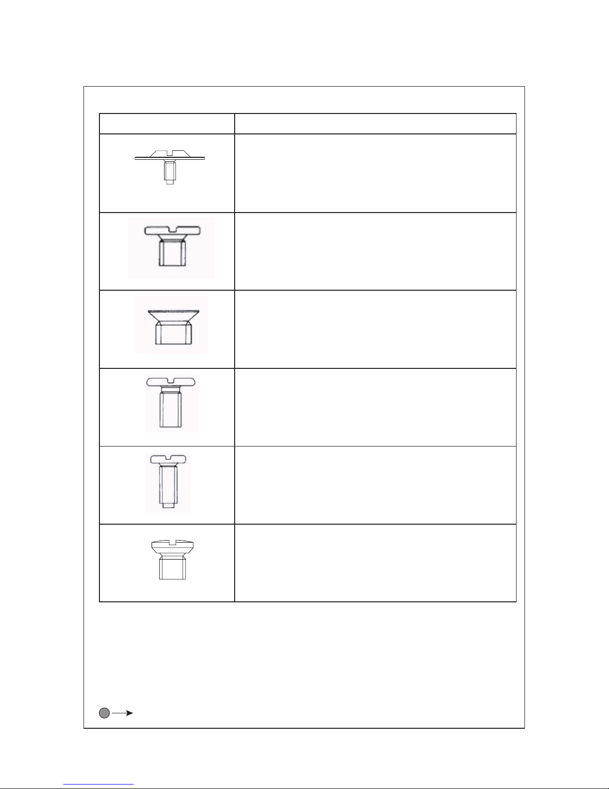
Cal. 4R35A
PARTS LIST
8/18
Please refer to the following pages.
0012 919
0012 354
e; RATCHET WHEEL SCREW
ek LOWER BRIDGE FOR CROWN WHEEL AND REDUCTION WHEEL
S
CREW
rg CENTER WHEEL BRIDGE SCREW
P
ALLET COCK SCREW (2 pcs)
AUTOMATIC TRAIN WHEEL SCREW (2 pcs)
Parts code
Parts name
rk SETTING LEVER JUMPER SCREW (2 pcs)
es BARREL AND TRAIN WHEEL BRIDGE SCREW (3 pcs)
wa BALANCE COCK SCREW
CASING CL AMP SCREW (2 pcs)
0
012 168
0012 420
0012 067
CROSS-SECTION VIEW OF THE SCREW PARTS
0016 705
3 DATE DISK GUARD SCREW B
Page 9
PARTS LIST
Cal. 4R35A
9/18
Please refer to the following pages.
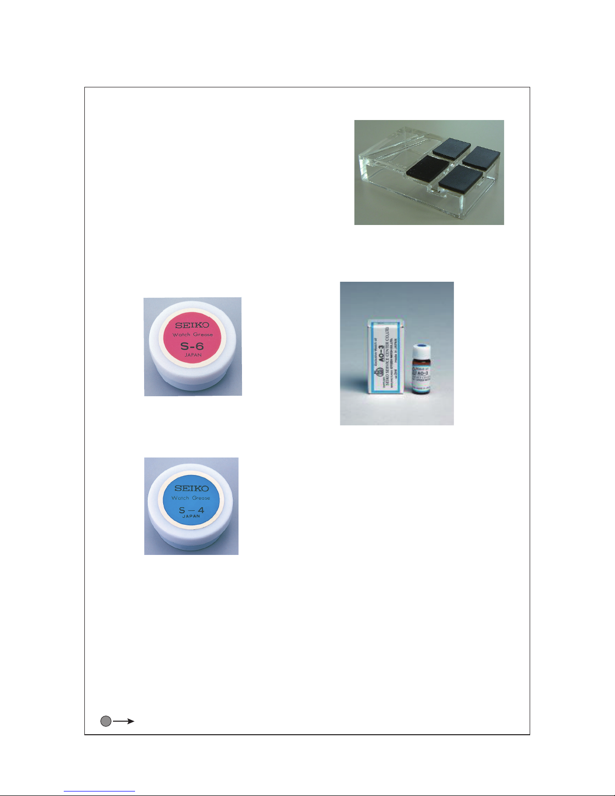
●
Tools and consumables required for disassembling/reassembling
• Movement holder
UNIVERSAL MOVEMENT HOLDER
(S-682)
•
Watch oils
SEIKO watch grease S-6 and S-4. watch oil AO-3 (or Moebius A)
S-6
AO-3
S-4
Page 10
TECHNICAL GUIDE
Cal. 4R35A
10/18
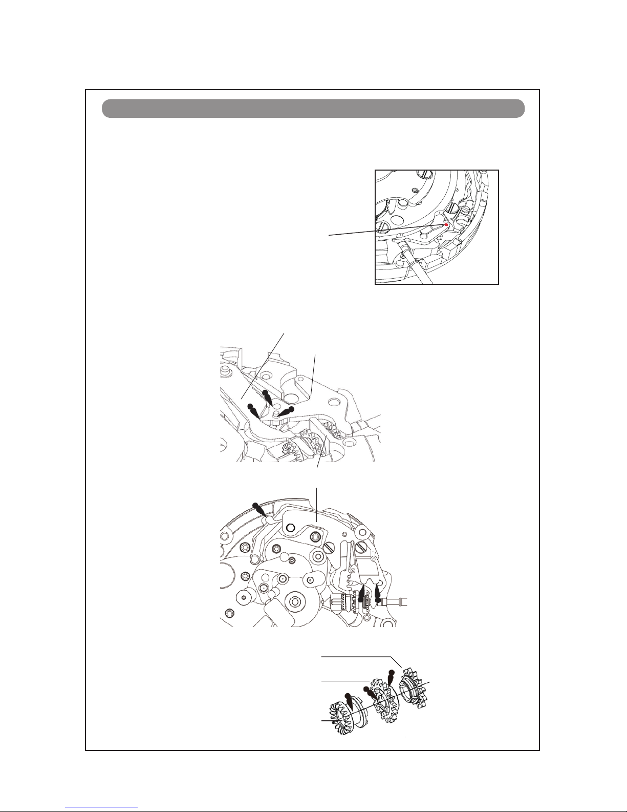
l
SETTING MECHANISM
Crown position: 0 position
Push the SETTING LEVER gently (refer to the picture on
the right) in order to disengage it from the SETTING
S
TEM. Then pull out the crown with stem completely.
Push here
ql
C
ALENDAR CORRECTOR 1ST INTERMEDIATE WHEEL
qk
WI
NDING PINION
qj
C
LUTCH WHEEL
REMARKS ON DISASSEMBLING AND REASSEMBLING THE MOVEMENT
l HOW TO REMOVE THE SETTING STEM
BEFORE DISMANTLING THE MOVEMENT
t;
YOKE
ta
SETTING LEVER
tl
SE
TTING LEVER JUMPER
Page 11
TECHNICAL GUIDE
Cal. 4R35A
11/18
l
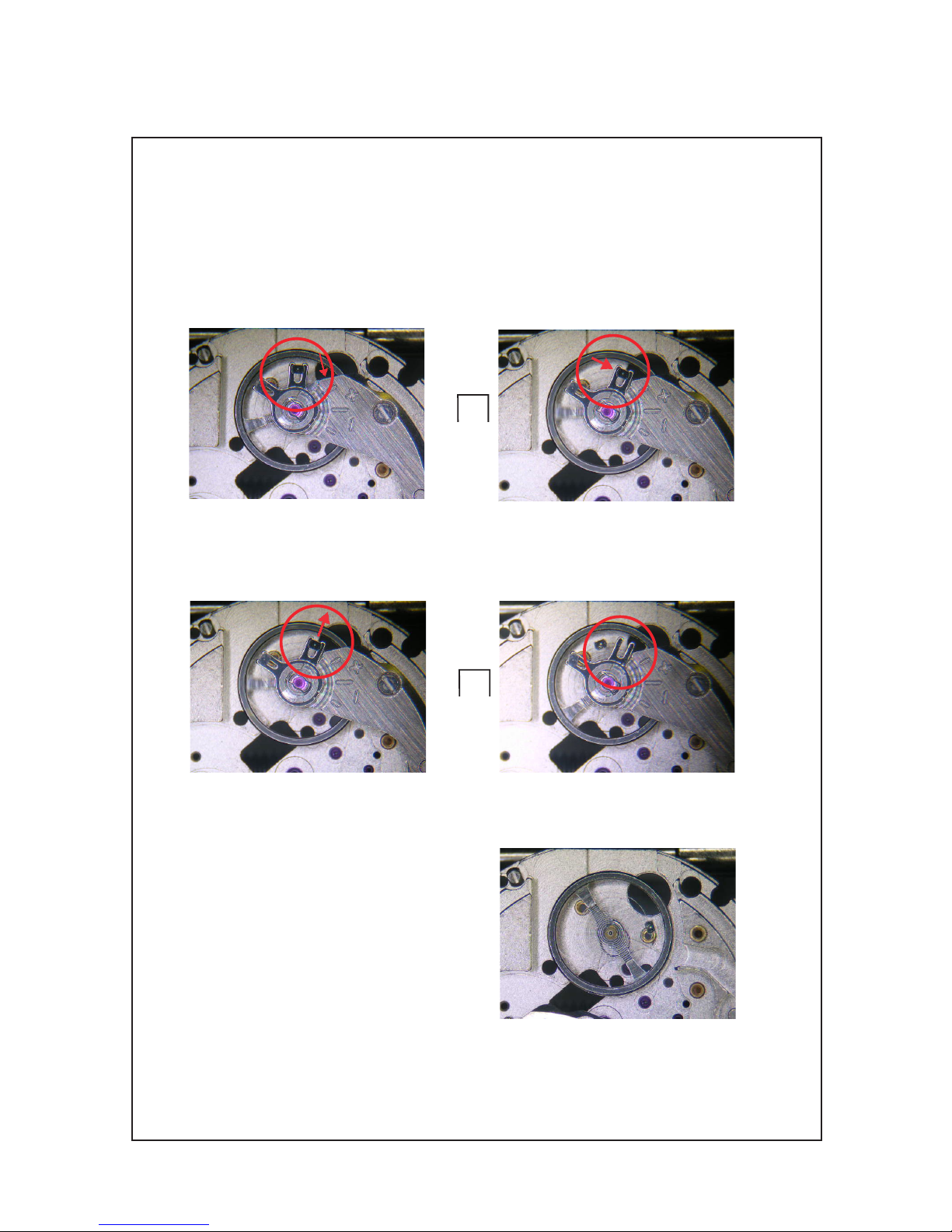
BALANCE AND ESCAPEMENT
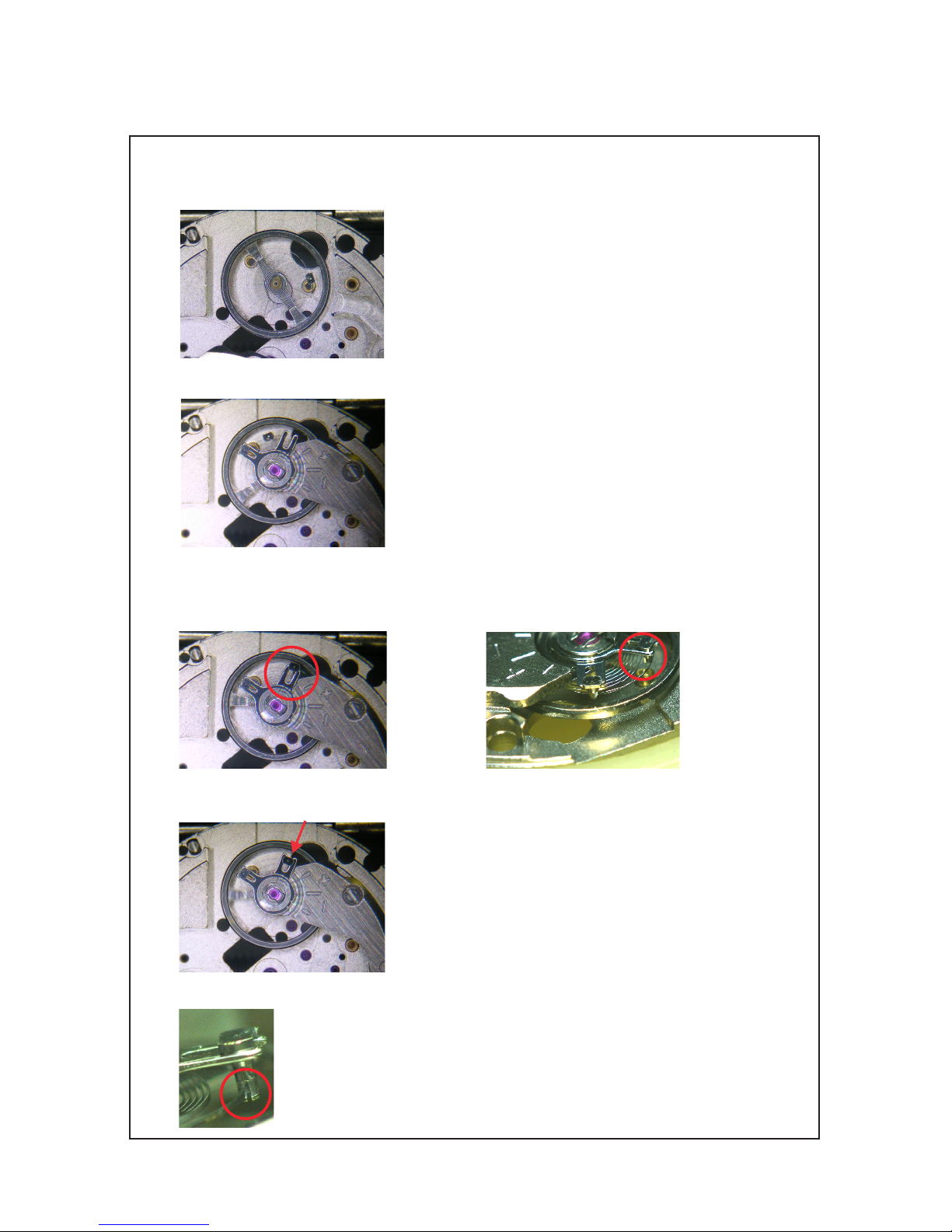
How to disassemble /reassemble the BALANCE and BALANCE COCK
•
Disassembling
1
) Rotate the STUD SUPPORT until it touches to the BALANCE COCK.
When doing so, make sure that the second bend of the balance-spring does not touch the
REGULATOR PIN.
2
) Push out the stud parallel to the slit of the STUD SUPPORT (the direction also shown by the red
arrow in the illustration) in order to remove it from the STUD SUPPORT.
3
) Unscrew the BALANCE COCK SCREW and remove the BALANCE COCK WITH REGULATOR.
4
) Remove the BALANCE COMPLETE WITH STUD.
Page 12
TECHNICAL GUIDE
Cal. 4R35A
12/18
•
Reassembling
1)Install the BALANCE COMPLETE WITH STUD to the MAIN PLATE.
2) Set the BALANCE COCK WITH REGURATOR and tighten the BALANCE COCK SCREW.
3) Temporarily set the stud to the STUD SUPPORT.
Do not engage the balance-spring to the REGULATOR PIN. The balance-spring passes outside of the
REGULATOR-PIN at this stage.
4) Push back the stud parallel to the slit of the STUD SUPPORT.
5) Engage the balance-spring with the slit of the REGULATOR PIN.
* When assembling the BALANCE COMPLETE, pay great attention
not to deform the balance-spring, especially at the second
bend.
Page 13
TECHNICAL GUIDE
Cal. 4R35A
13/18
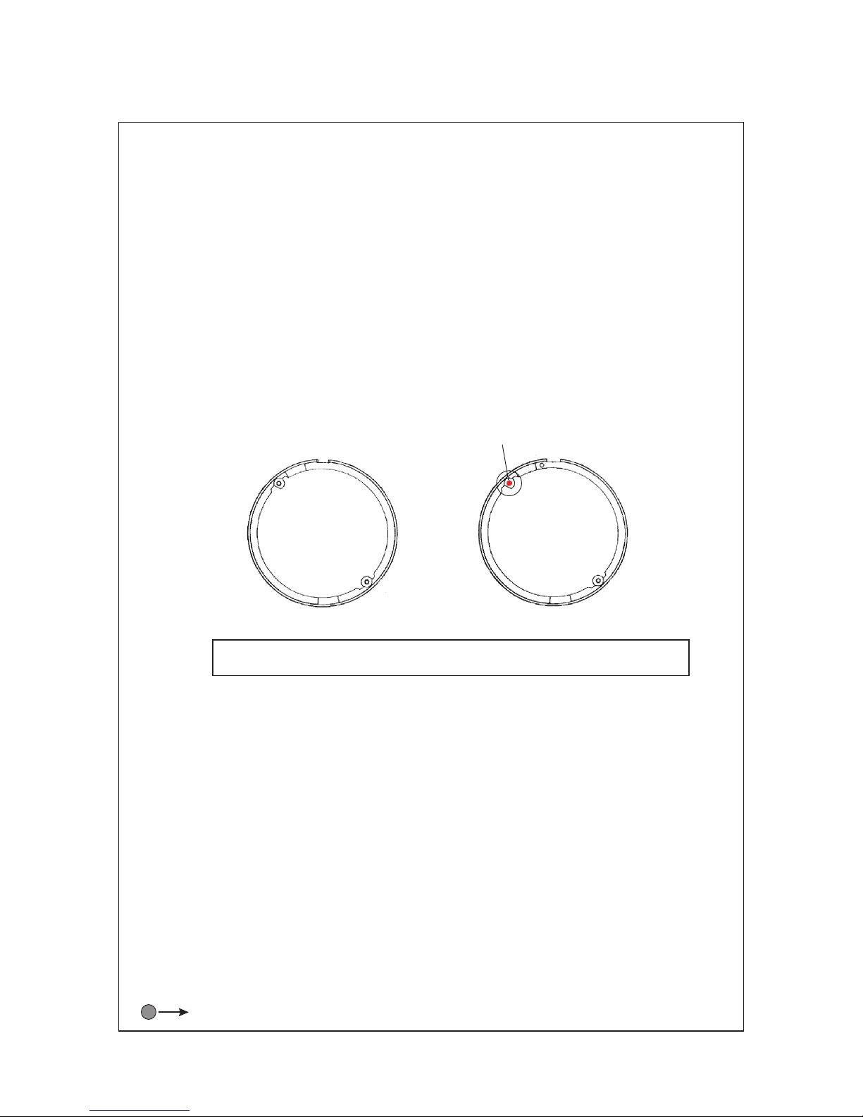
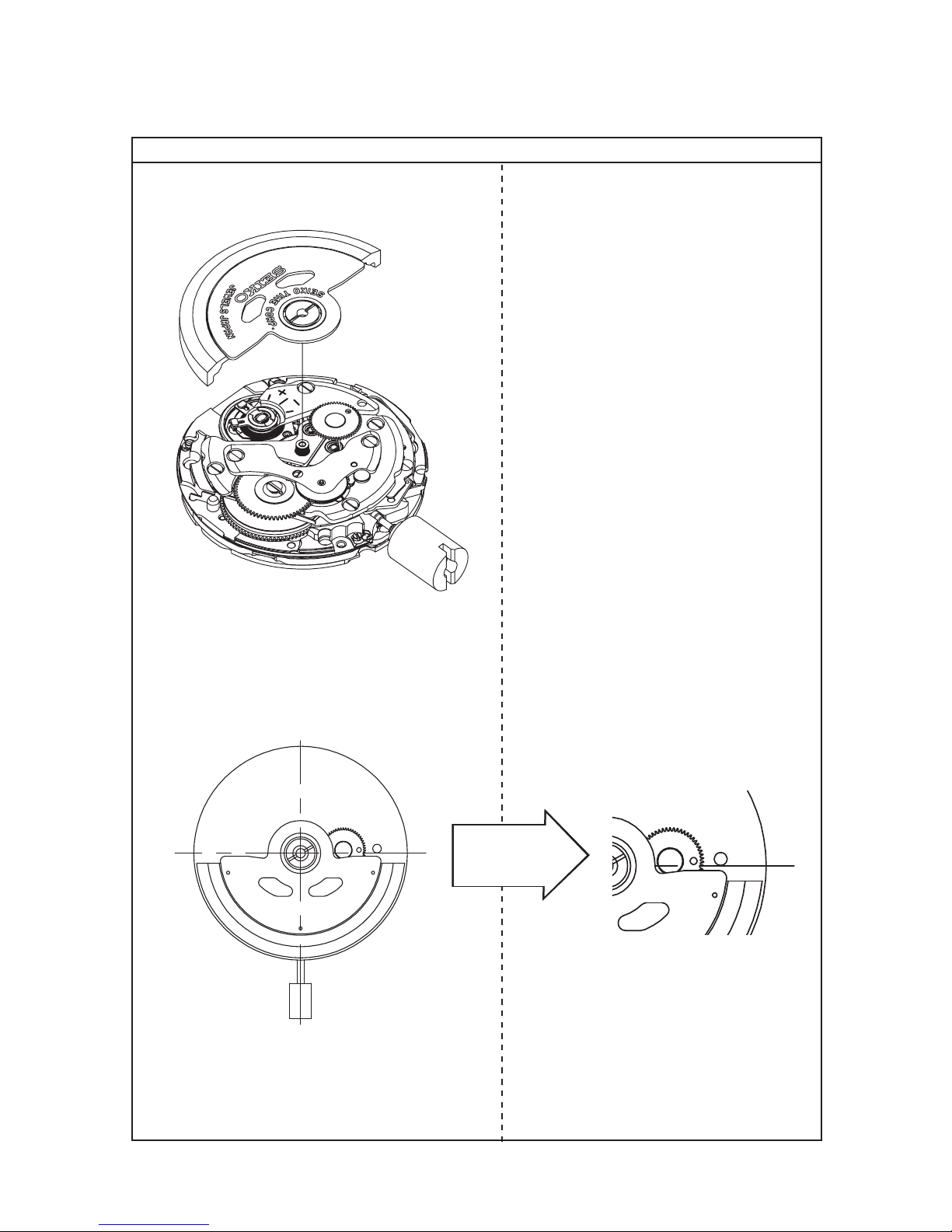
HOW TO REASSEMBLE OSCILLATING WEIGHT
Enlarged view
OSCILLATING WEIGHT
When fixing the OSCILLATING WEIGHT, an
alignment with the FIRST REDUCTION WHEEL
is necessary in order to wind the MAINSPRING
most ef ficiently.
R
otate the FIRST REDUCTION WHEEL manually
until its hole aligns with the gilt dot on the
BALAN
CE COCK and set the OSCILLATING
WEIGHT vertically at the stem side, and then
tighten the screw. Refer to the figure below.
Page 14
TECHNICAL GUIDE
Cal. 4R35A
14/18
l
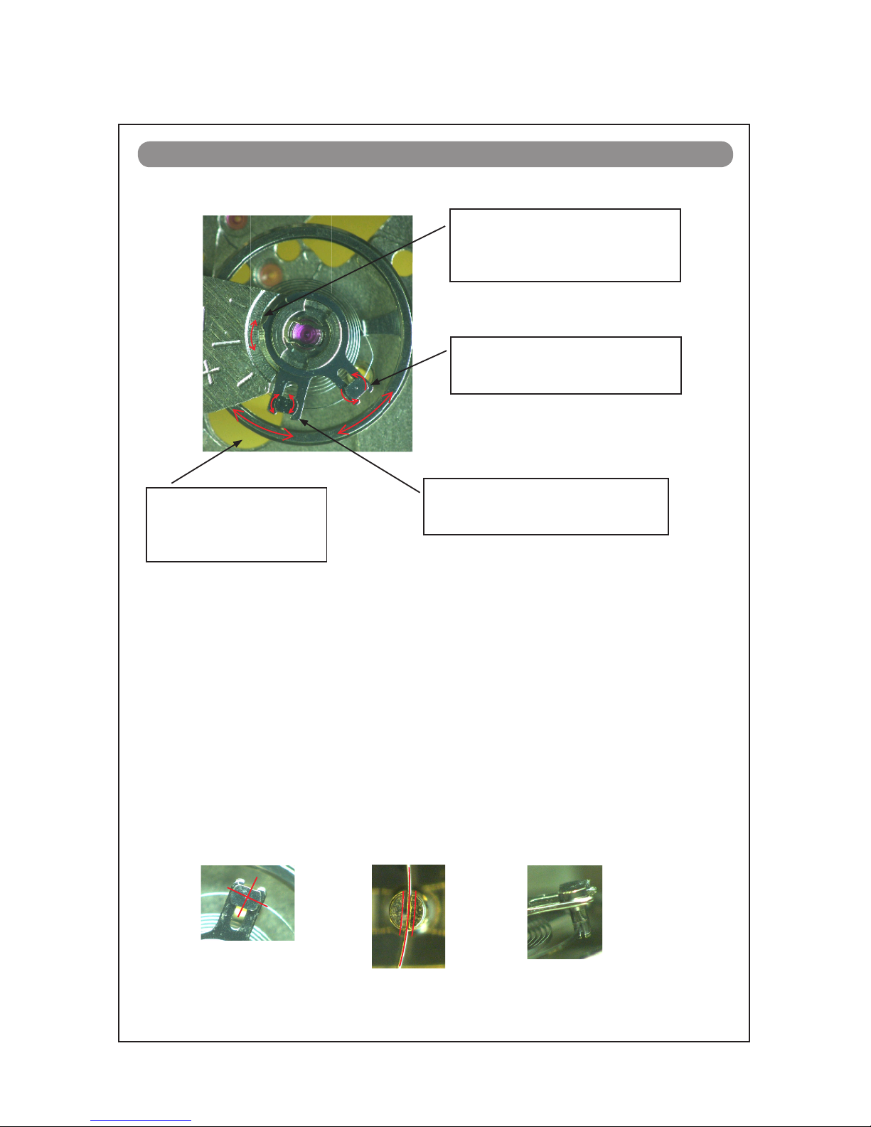
Names of the parts for regulation and their functions
[STUD SUPPORT]
Correction of the beat error
by positioning the roller jewel
correctly
[REGULATOR]
Regulation of the accuracy rate (+) or (-)
by adjusting the operative length of the
balance-spring
[STUD (glued at the balance-spring)]
Alignment of the balance-spring to the
center of the regulator pin's slit
[REGULATOR PIN]
Adjustment of the play of the balancespring embraced in its slit
l
How to regulate the isochronism fault by adjusting the position of the balance-spring
This caliber has the Etachron system for fine regulation of the isochronism fault, which is the same
design used for both Cal. 7S-B series.
Wh
en an amplitude of the balance becomes weak, the watch shows time loss, in general.
By making a clearance of the balance-spring smaller, the decline curve of the instantaneous rate
gets shallower.
1
) Make sure that the REGURATOR PIN is aligned in a vertical position to the REGURATOR and the
balance-spring passes parallel through the slot of the REGULATOR PIN before fine-tuning the STUD
and the REGULATOR PIN.
REGULATOR PIN
top side view back side view
angled view
1
2
3
4
1
2
3
4
2
REGULATION
Page 15
TECHNICAL GUIDE
Cal. 4R35A
15/18
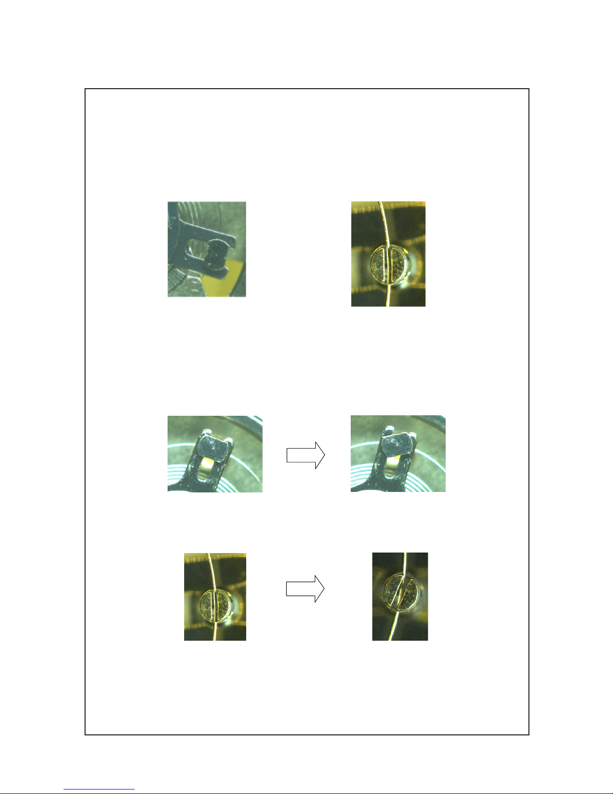
2) Rotate the STUD in order to align the position of the balance-spring passes through the center of
the slot of the REGULATOR PIN.
STUD
REGULATOR PIN
3) Rotate the REGULATOR PIN counterclockwise in order to fine-tune the clearance of the balance-spring
passing through the slot of it.
top side view
back side view
R
EGULATOR PIN
top side view
Before rotating
After rotating
back side view
Before rotating
Af
ter rotating
(Maximum clearance) (Minimum clearance)
Page 16
TECHNICAL GUIDE
Cal. 4R35A
16/18
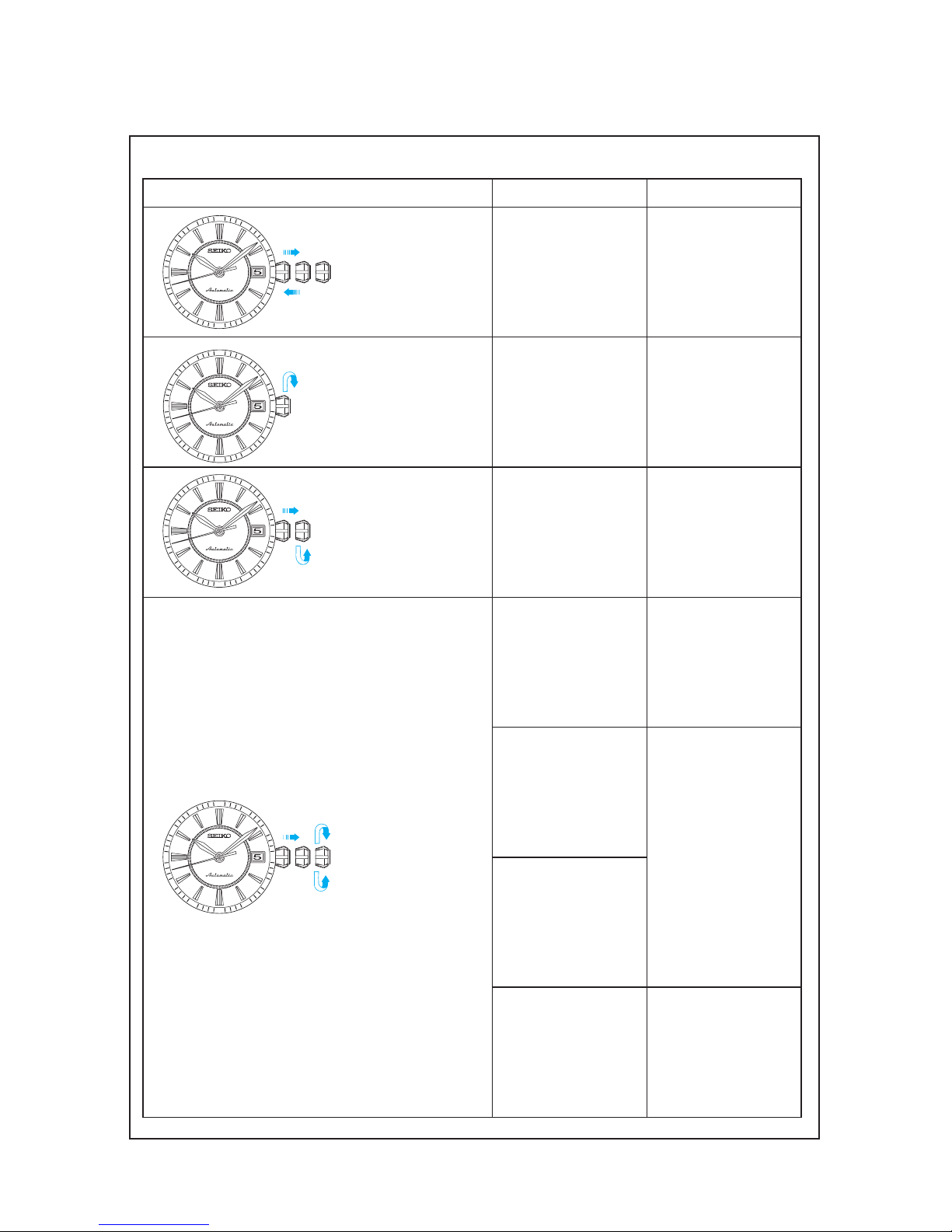
l
F
unction check
Operation Function Checkpoint
Pull out the crown to
the 2nd click and push
it back in to the normal
position. Repeat the
same several times.
Set ting m e cha n i s m
switching the function
of the time setting.
Make sure that it has a
click at each position
and the stem is not
pulled off.
Tu r n t h e c ro w n
clo c k w i se at t he 0
click.
H a
n d w i n d i n g
function.
Make s ure that t h e
mains p r ing c an b e
wound by turning the
crown clock wise.
Pull out the crown to
the 1st click, then turn it
counterclockwise.
Calendar mec hani sm
- correcting the date.
Make sure that the date
changes smoothly.
Pull out the crown to the
2nd click, then turn it.
Se c on d h a n d s to p
function.
Make s ur e t h a t t h e
second hand stops when
the crown is pulled out
to the 2nd click.
Setting mechanism hour and minute hand
setting.
Make sure that the hour
and minute hands move
s m oo t hl y ( w i t ho u t
touching each other or
touching the surface of
the dial or inside of the
glass).
Ha
nds installation.
calendar mechanism
- date change.
Make sure that the date
changes when the hour
and minute hands pass
around midnight.
5
35
10
15
40
55
25
60
30
50
45
20
5
35
10
15
40
55
25
60
30
50
45
20
5
35
10
15
40
55
25
60
30
50
45
20
5
35
10
15
40
55
25
60
30
50
45
20
Page 17
TECHNICAL GUIDE
Cal. 4R35A
17/18
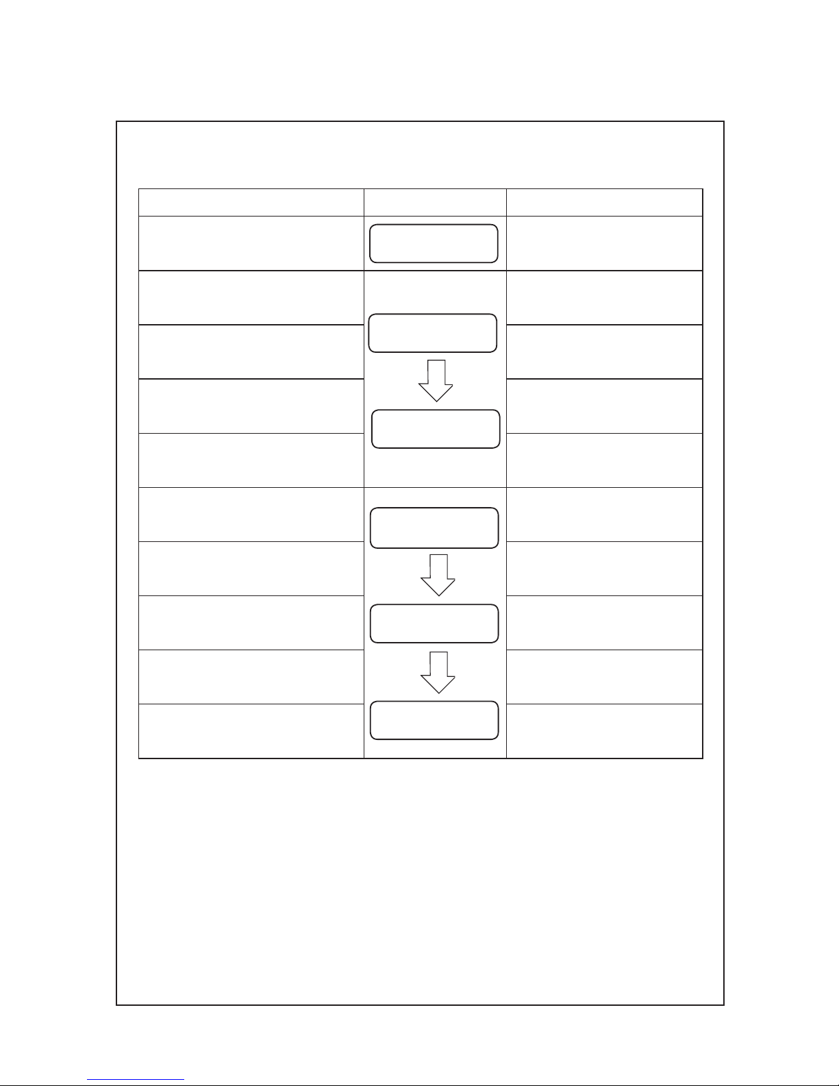
Marking on the case back Test method Applied pressure
WATER RESISTANT (WATER RESIST)
3 BAR
WATER RESIST 5BAR 5 BAR
WATER RESIST 10BAR 10 BAR
WATER RESIST 15BAR 15 BAR
WATER RESIST 20BAR 20 BAR
SCUBA DIVER'S (AIR DIVER'S) 150 m 18.75 BAR = 150 (m) times 0.125
SCUBA DIVER'S (AIR DIVER'S) 200 m 25 BAR = 200 (m) times 0.125
He-GAS DIVER'S 300 m 37.5 BAR = 300 (m) times 0.125
He-GAS DIVER'S 600 m 75 BAR = 600 (m) times 0.125
He-GAS DIVER'S 1000 m 125 BAR = 1000 (m) times 0.125
Check the water resistance according to the designated specification of the watch.
l
Water resistance test
Water pressure test
Condensation test
Condensation test
Condensation test
Water pressure test
Air leak test
Page 18
TECHNICAL GUIDE
Cal. 4R35A
18/18
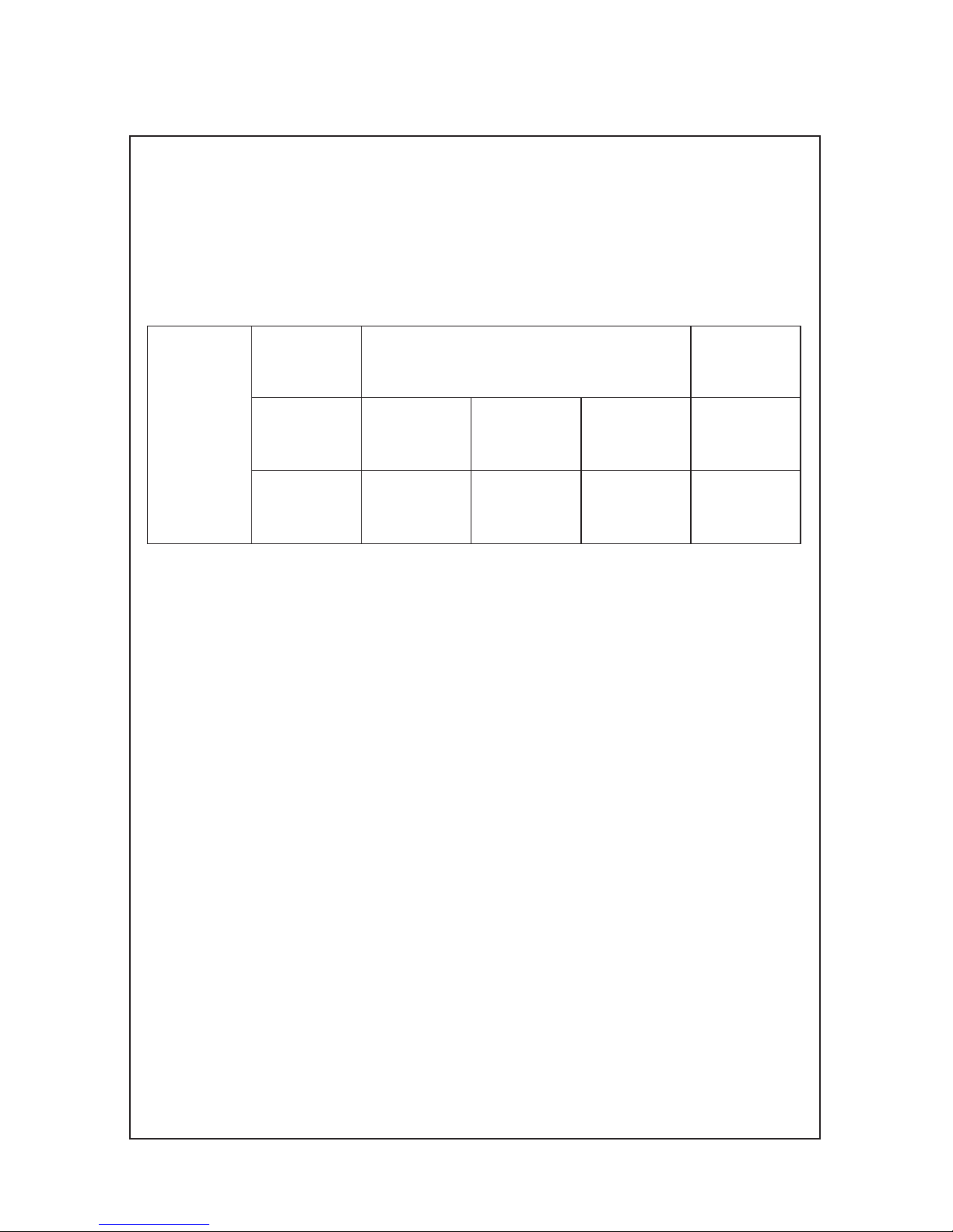
Measure the rate in three different positions within 30 minutes after the watch is fully wound up (wait
approximately for 5 minutes after winding up in order to get a stable oscillation of the balance) and
make sure the value shows within the range in the table below.
Measure the rate in dial-up position af ter 24 hours from fully wound up (T24) and check the rate
difference with the rate in dial-up position when it is fully wound up (T0). Make sure that the value of
T24-T0 shows within the range of the isochronism in the table below.
v T
he accuracy of mechanical watches is indicated by the daily rates of one week or so.
v T
he accuracy of mechanical watches may not fall within the specified range of time accuracy because
of loss /gain changes due to the conditions of use, such as the length of time during which the watch
is worn on the wrist, arm movement, whether the mainspring is wound up fully or not, etc.
v The key components in mechanical watches are made of metals which expand or contract depending on
temperatures due to metal properties. This exerts an effect on the accuracy of the watches. Mechanical
watches tend to lose time at high temperatures while they tend to gain time at low temperatures.
v I
n order to improve accuracy, it is important to regularly supply energy to the balance that controls
the speed of the gears. The driving force of the mainspring that powers mechanical watches varies
b
etween when it is fully wound and immediately before it is unwound. As the mainspring unwinds,
the force weakens.
v Relatively steady accuracy can be obtained by wearing the watch on the wrist frequently for the self-
winding type and winding up the mainspring fully everyday at a fixed time to move it regularly for the
wind-up mechanical type.
v
When affected by external strong magnetism, a mechanical watch may loss/gain time temporarily.
The parts of the watch may become magnetized depending on the extent of the effect. In such a case,
consult the retailer from whom the watch was purchased since the watch requires repair, including
demagnetizing.
Standard rate
for
measurement
Mainspring
wind up status
Fully wind up (T0)
Af
ter 24 hours
from fully wind
up (T24)
Testing
positions
Di
al upwards :
T0 (CH)
6 o'clock at the
top
9 o'clock at the
top
Di
al upwards :
T24 (CH)
Measurement
(daily rate in
seconds:s /d)
±20 s /d ±30 s/d ±30 s/d
( I s ochr o n i s m
faul t : T 24-T0)
±30 s/d
l
Duration time test
Check the Power reserve of the watch after the mainspring is fully wound up and leave it oon natural
condition with the dial-up position. Make sure that the watch runs approximately 41 hours until it
stops.
l
Accuracy test
ACCURACY OF MECHANICAL WATCHES
 Loading...