

Seiki LC-24G82,SC151FS Instruction Manual
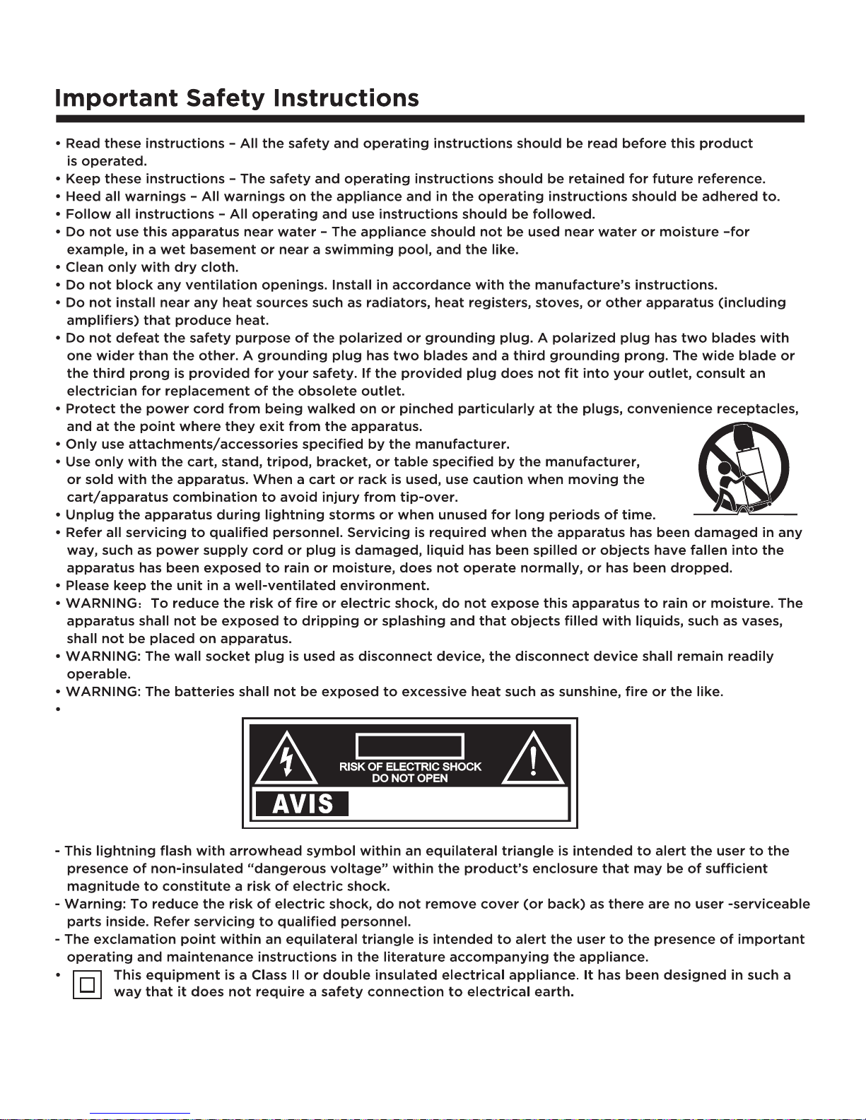
CAU T I O N
RISQUE CHOC ELECTRIQUE NE
PAS OUVRIR
2
3
26
26
23-25
22
20-21
19
17-18
21
4
5
6
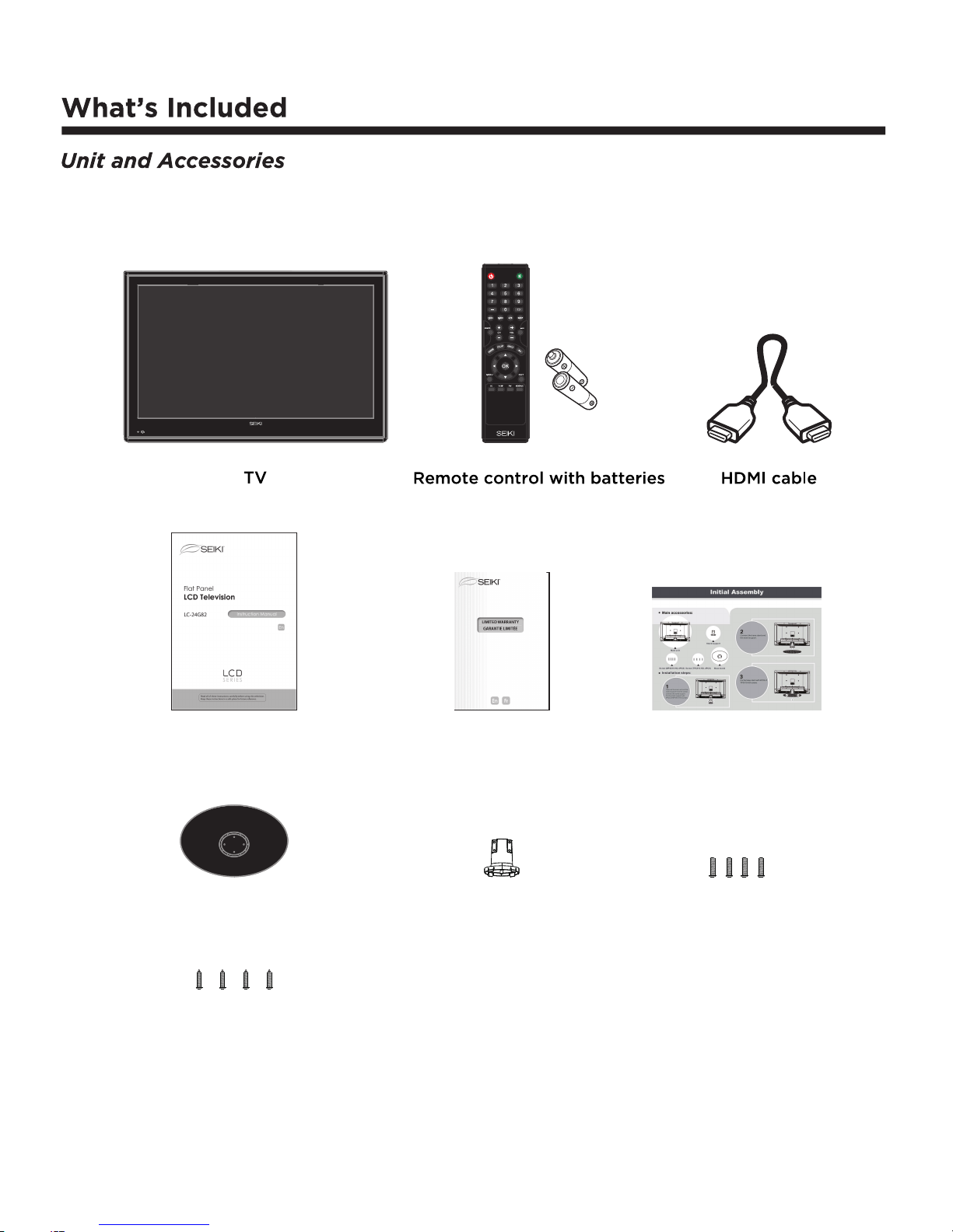
Stand sup port
Initial a ssemblyWarran ty cardUser’s manual
Base stand
Screw (TP3X10-HO, 4 PCS)
Screw (MP4X10-HO, 4PCS)
7
8 8
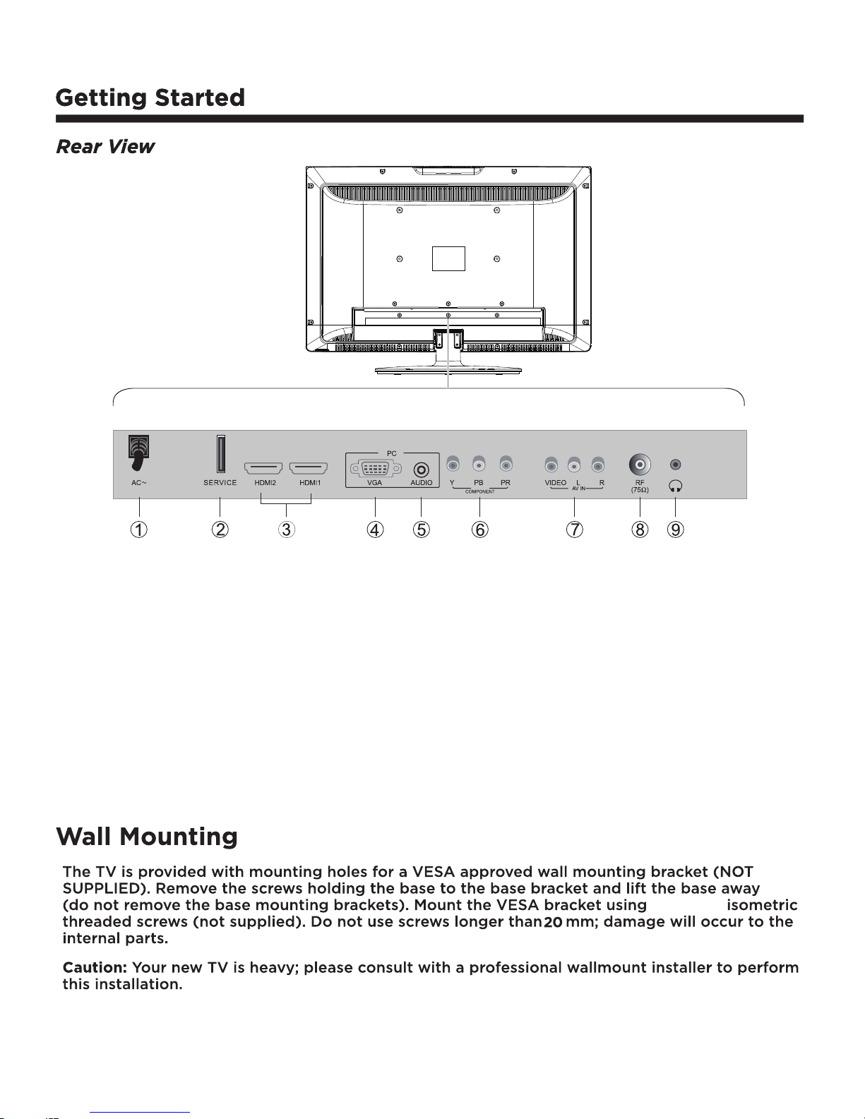
1. AC power input terminal.
2. SERVICE port.
3. HDMI1 / HDMI2 input.
4. VGA input.
5. PC audio input.
6. Component input terminal.
7. AV input.
8. Antenna input (75 Ohm VHF/ UHF).
9. Headphone output.
4 x M4x12
 Loading...