

Page 1
RR
UEM-8DR/8T SERIES
No.1, Lane 17, Sec. 2, Han Shi West Road, Taichung, 401 TAIWAN
Tel:886-4-22313737 Fax:886-4-22346757
http://www.show-pa.com e-mail: sekaku@sekaku.com
All rights reserved to SEIKAKU. All features and content might be changed
without prior notice. Any photocopy, translation, or reproduction of part of this
manual without written permission is forbidden. Copyright 2005 SEIKAKU GROUP
cc
NF03356-1.0
Page 2

IMPORTANT!
Please read this manual carefully before operating
this unit for the first time.
All rights reserved to SHOW. All features and content might be changed
without prior notice. Any photocopy, translation, or reproduction of part of
this manual without written permission is forbidden.
Page 3
SAFETY RELATED SYMBOLS
CAUTION
RISK OF ELECTRIC SHOCK
DO NOT OPEN
The symbol is used to indicate that some
hazardous live terminals are involved
within this apparatus, even under the
normal operating conditions.
The symbol is used in the service documentation to indicate that specific
component shall be only replaced by
the component specified in that documentation for safety reasons.
Protective grounding terminal.
Alternating current /voltage.
Hazardous live terminal .
ON: Denotes the apparatus turns on.
OFF: Denotes the apparatus turns off, be-
cause of using the single pole switch, be sure
to unplug the AC power to prevent any electric shock before you proceed your service.
WARNING: Describes precautions that
should be observed to prevent the danger
of injury or death to the user.
Disposing of this product should
not be placed in municipal waste
and should be separate collection.
CAUTION: Describes precautions that
should be observed to prevent danger of the
apparatus.
WARNING
Power Supply
Ensure the source voltage matches the
voltage of the power supply before turning
ON the apparatus.
Unplug this apparatus during lightning
storms or when unused for long periods
of time.
External Connection
The external wiring connected to the output hazardous live terminals requires
installation by an instructed person, or
the use of ready-made leads or cords.
Do not Remove any Cover
There are maybe some areas with high
voltages inside, to reduce the risk of electric
shock, do not remove any cover if the power
supply is connected.
The cover should be removed by the qualified personnel only.
No user serviceable parts inside.
Fuse
To prevent a fire, make sure to use fuses
with specified standard (current, voltage,
type). Do not use a different fuse or short
circuit the fuse holder.
Before replacing the fuse, turn OFF the
apparatus and disconnected the power
source.
Protective Grounding
Make sure to connect the protective
grounding to prevent any electric shock
before turning ON the apparatus.
Never cut off the internal or external protective grounding wire or disconnect the
wiring of protective grounding terminal.
Operating Conditions
This apparatus shall not be exposed to
dripping or splashing and that no objects
filled with liquids, such as vases, shall be
placed on this apparatus.
To reduce the risk of fire or ele ctric shock,
do not expose this apparatus to rain or
moisture.
Do not use this apparatus near water.
Install in accordance with the manufactu rer's
Page 4

instructions. Do not install near any heat
This device complies with Part 15 of the
FCC Rules. Operation is subject to the
condition that this device does not cause
harmful interference.
NOTE: This equipment has been tested and found
to comply with the limits for a Class B digital
device, pursuant to Part 15 of the FCC Rules.
These limits are designed to provide reasonable
protection against harmful interference in a
residential installation. This equipment generates,
uses and can radiate radio frequency energy and,
if not installed and used in accordance with the
instructions, may cause harmful interference to
radio communications. However, there is no
guarantee that interference will not occur in a
particular installation. If this equipment does cause
harmful interference to radio or television
reception, which can be determined by turning the
equipment off and on, the user is encouraged to try
to correct the interference by one or more of the
following measures:
-- Reorient or relocate the receiving antenna. --
Increase the separation between the equipment
and receiver. -- Connect the equipment into an
outlet on a circuit different from that to which the
receiver is connected.-- Consult the dealer or an
experienced radio/TV technician for help.
*This device normal operated more than
body 5 cm
sources such as radiators, heat registers,
stoves, or other apparatus (including amplifiers) that produce heat. Do not block
any ventilation openings.
No naked flame sources, such as lighted
candles, should be placed on the apparatus.
IMPORTANT SAFETY INSTRUCTIONS
Read these instructions.
Follow all instructions.
Keep these instructions.
Heed all warnings.
Only use attachments/accessories spec-
ified by the manufacturer.
Power Cord and Plug
Do not defeat the safety purpose of the
polarized or grounding type plug.
A polarized plug has two blades with
one wider than the other. A grounding
type plug has two blades and a third
grounding prong. The wide blade or the
third prong are provided for your safety.
If the provided plug does not fit into your
outlet, consult an electrician for replacement of the obsolete outlet.
Protect the power cord from being walked on or pinched particularly at plugs,
convenience receptacles, and the point
where they exit from the apparatus.
Cleaning
When the apparatus needs a cleaning, you
can blow off dust from the apparatus with
a blower or clean with rag etc.
Don't use solvents such as benzol, alcohol,
or other fluids with very strong volatility and
flammability for cleaning the apparatus body.
Clean only with dry cloth.
Servicing
Refer all servicing to qualified personnel. To
reduce the risk of electric shock, do not perform
any servicing other than that contained in the
operating instructions unless you are qualified
to do so .
Servicing is required when the apparatus has
been damaged in any way ,such as power
supply cord or plug is damaged , liquid has
been spilled or objects have fallen into the
apparatus, the apparatus has been exposed
to rain or moisture, does not operate normally,
or has been dropped.
WARNING: changes or modifications
not expressly approved by the party
responsible for compliance could void
the user's authority to operate the
equipment.
Page 5

6. ANNEX
The frequencies which corresponds to the channels are as follows.
TABLE OF CONTENTS
1. .. . 1INTRODUCTION . ..................................................................................
CHANNEL
F5 702-731
1 2
3
702.125 702.875 703.775 705.875
CHANNEL
F5 702-731
CHANNEL
F5 702-731
CHANNEL
F2 535-564
7 8
702.500
703.250 704.150 706.250
13 14
714.725 714.925
1 2
9 10
15
725.475 730.725
3
535.125 535.875 536.775 538.875
CHANNEL
F2 535-564
CHANNEL
F2 535-564
7 8
535.500
536.250 537.150 539.250
13 14
547.725 547.925
9 10
15
558.475 563.725
Remark: FCC only for F2:535-564MHz
4
16
4
16
5 6
724.875
11
725.250
5 6
557.875
11
558.250
730.125
12
730.500
563.125
12
563.500
2. ...... ......... . ........... . ....................2FEATURES .... . ..................... ..... ...............
3. .... . .. .... ......... .............2CONTROL ELEMENTS ........ . ..... .......................... ..
4. ... .. ... ... . ... . . ....................4OPERATION ... .. .. ... ...................... ..... ........ ..........
5. SPECIFICATIONS..................................................................................6
6. ANNEX....................................................................................................7
7
Page 6

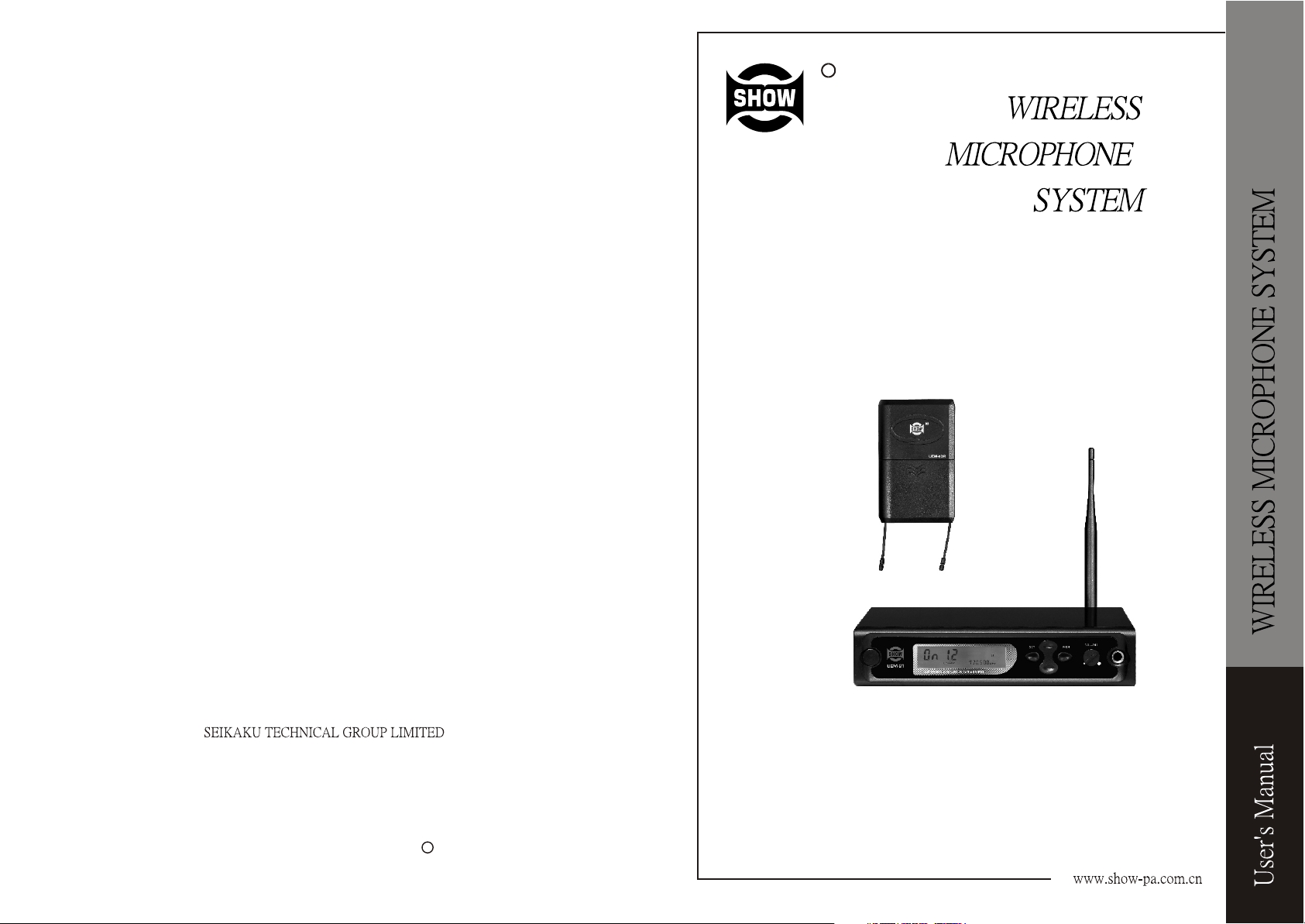
1. INTRODUCTION
Thank you for purchasing UEM monitoring system. It has many advantages of in-ear
monitoring including: better sound quality, more mobility, personal adjustment,
etc. Better sound quality means high fidelity without risky feedback. More mobility
means the mix is mobile with the owner together. Personal djustment means it
forms a personal mix, and adjusts the personal levels.
The UEM Monitor System
The UEM monitor system is a frequency-sensitive system with in-ear monitor,
which is used in a wide range of applications. The product is suitable for school
speech, meeting speech, teachers and performer on stage.The features aid to
solve the problems from stage monitoring.
The UEM-8DR is new bodypack receiver which works as a wired receiver, a wireless
receiver, or both at the same time. The UEM-8T is another unique design for in-ear
monitoring.
Connect the two line-level or MIC level inputs directly into the transmitter and
then the two signals can be mixed together. Connect microphones or instruments
directly with the inputs or with UEM-8T, and use line outputs from a mixing console.
In a word, no matter what kind of output device you use, it can be plugged into
The whole UEM monitor series include the EB earphones and it has a dynamic
driver to produces crisp, full-spectrum sound. They have various sleeve options
for the best fit and isolation for ears. The EB earphone can operate wellwith CD
players, MP3 players, and anything else with a 1/5 inch (3-5mm) stereo output.
UEM-8T
UEM-8DR Receiver
5. Specifications
MODEL
Frequency range
Frequency response
Total harmonic distortion
Signal to noise ratio
Maximum output level
Audio output connector
Power requirements
Current drain
Dimensions
4.2L x 0.9Wx 2.6 H inch
Net weight 80g (0.177bs)
MODEL
Frequency range
Frequency stability
Antenna output
RF output power
1=100mW
Maxiumum Deviation
AF frequency response
Modulation
Spurious emission
Power supply extend DC
Headphone output
470~870 MHz (FCC only for F2:535-564MHz)
50Hz TO 15KHz
1.5%
80dB
20mW
3.5mm stereo
9V alkaline battery
75mA
106(L) x 23(W) x 66(H) mm
UEM-8T
470-870MHz FCC only for F2:535-564MHz)(
0.005% at 25
TNC socket 50
0=30mW
60K
50-15KHz
Stereo FM working on the "pilot tone" principle
55dBc (type)
12-15V 550 mA AC/DC adaptor
1/4 (6.3mm) stereo jack
UEM-8DR
AF inputs
THD at 1kHz
Dimensions
8.27" x 9.13" x 1.73"
Weight
1
XLR/6.3mm , RCA line
1.2%
210(W) X 232(D) X 44(H)mm
1.45Kg (3.21lb)
6
Page 7

mode of selecting channel. Use UP or DOWN key to select the channel you want. When
one channel is selected, the corresponding frequency is presented. If one channel is
selected, press MEM key to save it. If one channel is selected from the transmitter, select
the corresponding channel from receiver.
Notes: For frequencies of channels in detail, please refer to the Annex.
4.2.3 RF output power
Press SET key three times and RF power could be then set. Use UP and DOWN key to
adjust the audio output power. The output power has two choices, 0 stands for 10mV, 1
stands for 100mV. When the RF power has been set, please press MEM key to save it.
4.3 UEM-8DR RECEIVER
4.3.1 Turn on the power switch
4.3.2 Select the channel which corresponds to that of the transmitter.
4.3.3 Put the ear phone plug into stereo socket for listening.
4.3.4 Adjust the volume control Adjust the volume by turning the volume control.
4.3.5 Battery Replacing & Installation
The double colour LED turns red, this indicates the battery low. Please replace
them with new batteries.
Please pay attention to that battery positive/negative should exactly correspond
to that of the receiver before the battery replacement. There is explosion
danger if the battery is incorrectly replaced. Replace the battery only with the
same or equivalent type.
Note:
1 After operation the unit should be switched off as well. Otherwise the batteries
will soon be exhausted. If LED of receiver lights up green, this indicates that the
.
receiver works well. If LED lights up red, this indicates that the wireless receiver
do not work. Please check if the channel is the right one which corresponds to
that of the transmitter. .
CAUTION
1 Battery use DC9V.
2 Do not drop the ear phone body on the floor.
3 Protect the unit from humidity and heat.
4 If the units don't work, bring them to technical engineer for disposal.
5 Volume level should not be too loud in case ears are hurt.
2. Features
UEM monitor system
-16 channels /frequencies selectable (Each channel corresponds to a frequency)
-EB dynamic driver earphones included
-Mono mix
UEM-8T
-2 mic/line XLR 1/4 inch combo inputs
- Input level adjustment
UEM-8DR Receiver
-Gain switch adjusting line input sensitivity
-1/4 inch line-level input jack for the connection with monitor mix, click tracks effects
-Cable management groove protects cables connected with bodypack
3. CONTROL ELEMENTS
3.1 UEM-8T
THE FRONT PANEL
6 7
1
4
5
3
2
1. Power switch
It switches on/off the main power of UEM-8T.
2. Headphone output
This is a 6.3mm phone jack for headphone monitoring.
3. Headphone volume control
It controls volume level for headphone.
4. LCD display
The LCD shows RF signal, group value, channel value, audio level and the selected
frequency.
5. UP/DOWN key
In this menu mode, you can choose the right value via these two keys.
5
2
Page 8

6. SET key
Via this key, you can choose the right function you want.
7. MEM key
This key is used to save the exact function you select.
THE REAR PANEL
911
10
8
8 .MIC input
This is a jack for inputting MIC signal.
9
.Input m ode
There are totally four input modes here. They are 1-MIXER/CD PLAYER,
2-CASSETTE PLAYER, 3-RADIO TUNER, 4-AUX INPUT respectively.
10
.DC input socket
It is used to connect an attached adapter.
11
.
Antenna
This antenna transmits signal for receiver. To get effective transmission, never
cover the antenna with hand, clothes, etc during the operation, and always
position the transmitter nearby the receiver.
4 LED indicator
When LED lights up red, it means battery power is insufficient. When the LED lights
up green, it means the receiver is in normal operation.
5 Battery cover
6 Channel selector control
It is used to select the channels 1~16 for the receiver.
7
Label
8 Belt clip
It is the detachable belt clip for easy carry during the live applications.
4. OPERATION
4.1 Make the right connection for the system
4.1.1. Please make sure first the voltage is correct, and then plug the power
supply cord into DC INPUT jack.
4.1.2. Install the antenna for UEM-8T.
4.2 UEM-8T TRANSMITTER
3.2 UEM-8DR
1
2
4
3
7
8
5
6
1 Stereo socket
This is a 3.5 jack for listening stereo signal or mono signal.
2 Volume control
It controls the volume of receiver.
3 Power switch
When power switch is set in the position OFF, the receiver is switched off.
When the power switch is set in the middle, the receiver is switched on and it
receives stereo signal. When the power switch is set in the position ON which the
silkscreen shows, it receives mono signal.
3
4.2.1 Turning on/off RF signal
Press SET key once and use UP and DOWN key to switch ON/OFF RF signal. If "ON"
remains flashing, it means the RF signal is turned on. If "OFF" remains flashing, it
means the RF signal is turned off. Then press MEM key to save it.
4.2.2 Selecting channel
Press SET key twice, and "channel" keeps flashing. It means the unit is in the
4
 Loading...