


Table of Content 6105303
1. User manual 2 ..................................................................................................................................
2. Legal regulations 2 .........................................................................................................................
3. Safety instructions 3 ......................................................................................................................
4. Controller functions 4 .....................................................................................................................
5. Functional principle 7 .....................................................................................................................
6. Technical data 8 ..............................................................................................................................
7. Mounting 9 .......................................................................................................................................
8. Mounting Principle 10 .....................................................................................................................
9. Dimensions (H x W x D) 11 .............................................................................................................
10. Electrical connection 12 ...............................................................................................................
11. Wiring diagram 12 .........................................................................................................................
12. Taking into operation 14 ..............................................................................................................
13. Trouble shooting 14 ......................................................................................................................
14. Maintenance & Cleaning 14 .........................................................................................................
15. Maintenance 15 .............................................................................................................................
16. Transport & Storage 15 ................................................................................................................
17. Parts supplied 15 ..........................................................................................................................
Version Nr. 1-8 - 17.01.2020 Doc. Nr. 996105303 1 / 15

1. User manual
This instruction manual contains information and instructions to enable the user to work safely, correctly and
economically on the unit. Understanding and adhering to the manual can help one:
Avoid any dangers.
Reduce repair costs and stoppages.
Extend and improve the reliability and working life of the unit.
PLEASE ENSURE TO USE THE RIGHT VERSION OF THE INSTRUCTION MANUAL SUITABLE FOR YOUR
UNIT.
Conditions of use
The unit is to be used exclusively for the dissipation of heat from control cabinets and enclosures in order to
protect temperature sensitive components in an industrial environment. To meet the conditions of use, all the
information and instructions in the instruction manual must be adhered to.
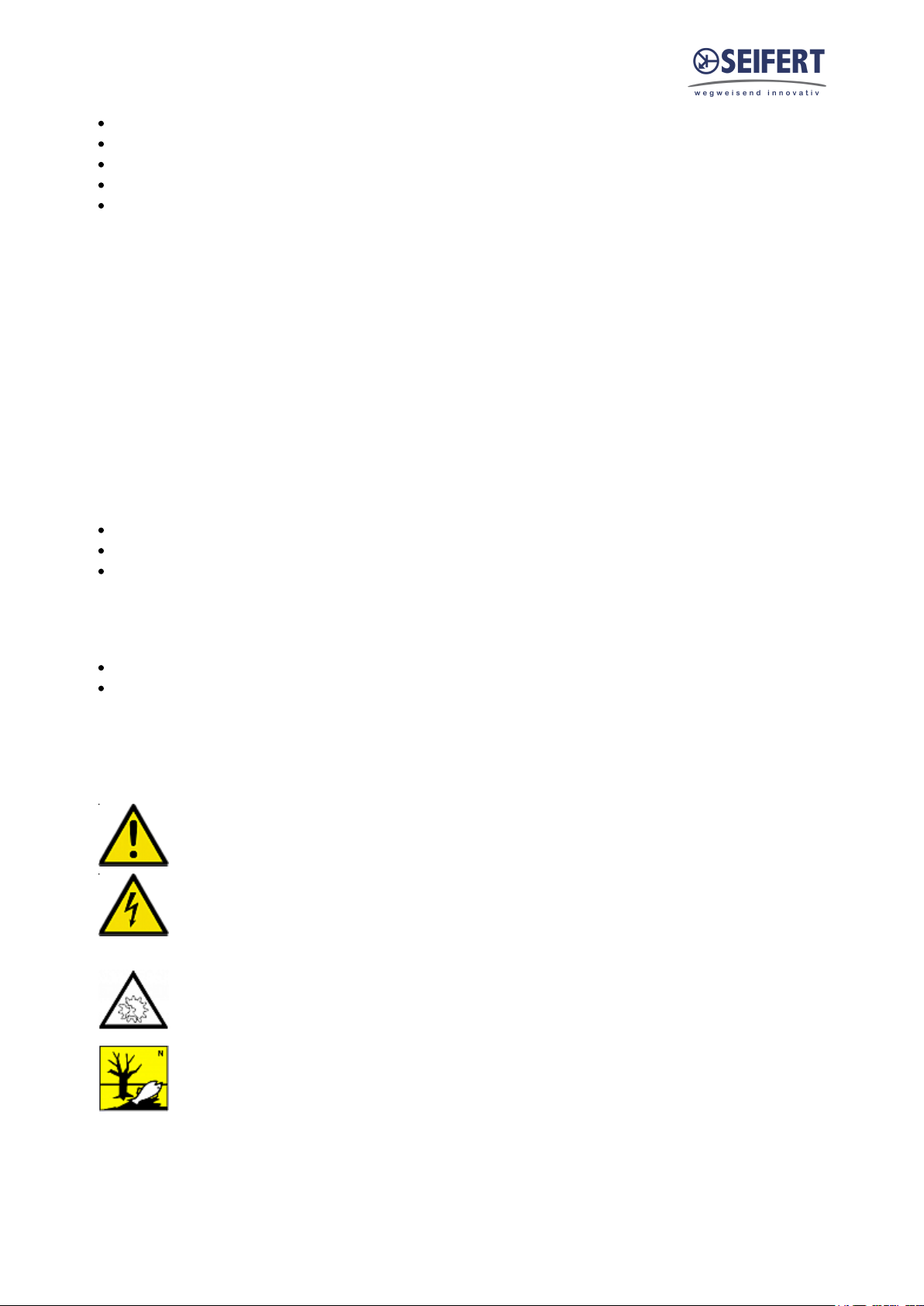
General danger
Indicates compulsory safety regulations which are not
covered by a specific pictogram such as one of the following.
High electric voltage
Indicates electric shock danger.
Important safety instruction
Indicates instructions for safe maintenance and operation of
the unit.
Attention
Indicates possible burns from hot components.
Attention
Indicates possible damage to the unit.
Instruction
Indicates possible danger to the environment.
2. Legal regulations
Liability
The information, data and instructions contained in this instruction manual are current at the time of going to
press. We reserve the right to make technical changes to the unit in the course of its development. Therefore,
no claims can be accepted for previously delivered units based on the information, diagrams or descriptions
contained in this manual. No liability can be accepted for damage and production caused by:
Version Nr. 1-8 - 17.01.2020 Doc. Nr. 996105303 2 / 15
Disregarding the instruction manual
Operating error
Inappropriate work on or with the unit
The use of non-specified spare parts and accessories
Unauthorised modifications or changes to the unit by the user or his personnel
The supplier is only liable for errors and omissions as outlined in the guarantee conditions contained in the main
contractual agreement. Claims for damages on any grounds are excluded.
3. Safety instructions
Upon delivery the unit is already meeting current technical standards and can therefore be safely taken into
operation. Only authorised personnel is allowed to work on the unit. Unauthorised personnel must be prohibited
from working on the unit. Operating personnel must inform their superiors immediately of any malfunction of
the unit.
Please note that before starting to work on or with the unit, a procedure must be carried out inside the cabinet
on which the unit is to be mounted.
Before commencing work inside the cabinet, the control cabinet manufacturer's instruction must be read with
regards to:
Safety instructions.
Instructions on taking the cabinet out of operation.
Instructions on the prevention of unauthorised cabinet reconnection.
The electric equipment meets the valid safety regulations. One can find dangerous voltages (above 50 V AC or
above 100 V DC)
Behind the control cabinet doors.
On the power supply in the unit housing.
The unit has to be operated according to the type plate and the wiring diagram, and must be protected
externally from overloading and electrical faults via suitable protective devices such as ground fault protection
breakers.
Danger through incorrect work on the unit
The unit can only be installed and maintained by technical competent and qualified
personnel, using only supplied material according to the supplied instructions.
Danger from electrical voltage
Only specialised personnel are allowed to maintain and clean the unit. The personnel must
ensure that for the duration of the maintenance and cleaning, the unit is disconnected from
the electrical supply.
Attention
Damage to the unit through the use of inappropriate cleaning materials. Please do not use
aggressive cleaning material.
Instruction
Damage to the environment through unauthorised disposal. All spare parts and associated
material must be disposed according to the environmental laws.
Version Nr. 1-8 - 17.01.2020 Doc. Nr. 996105303 3 / 15

4. Controller functions
Peltier cooling units are intended to be used as a complementary accessory to larger industrial equipment. They
are used where heat needs to be dissipated from electrical control cabinets or similar enclosures in order to
protect heat sensitive components.
Peltier cooling units can dissipate heat from sealed enclosures such as control cabinets. At the same time they
can reduce the cabinet internal temperature to below the ambient air temperature. They are available in
powder-coated sheet steel or stainless steel housings. Peltier units have additional heating function by changing
the supply polarity of the thermoelectric elements. This is possible by using a combination of thermostats or
having a specific polarity controller.
Peltier air conditioners are resistant to extreme ambient conditions and can operate effectively even in
environments which are dusty and oily and where temperatures may vary from -20°C to +65°C. For the cooling
capacities and evironmental ratings please refer to the type plate data.
Controller
The display shows the temperature in the range of -50°C to +150°C (-58°F to +302°F). The temperature is
displayed with resolution of tenths between -19.9°C and +99.9°C (-3.8°F to +211.8°F). During programming, it
shows the codes and values of the parameters. The display also shows icons according to occurring events.
Display icons
Icon Function Description
1 Cooling relay active
2 Alarms relay active
3 Heating relay active
4 Ambient blower relay active
Alarm Flashes when alarms are active
Cooling mode Signals operation of unit in cooling mode
TEST Test mode in progress Activated only by manual procedure
Programming
The operating parameters can be modified using the front keypad. Access differs depending on the type of
parameter. Access to configuration parameters is protected by a password that prevents unwanted
modifications or access by unauthorised persons.
Flashes when activation
is delayed or inhibited by
protection times, external
disabling or other procedures
in progress
Version Nr. 1-8 - 17.01.2020 Doc. Nr. 996105303 4 / 15

Setting cooling set point, St1:
1. Press “SET” and display should show St1 and then the pre-set value of St1. (default: +35°C / +95°F)
2. Reach the desired value by using ▲ or ▼.
3. Press “SET” again to save the new value of St1.
Setting temperature units (°C / °F), low temperature alarm and high temperature alarm:
1. Press “PRG” button for 5 seconds to reach the modifiable parameter list.
2. Use ▲ or ▼ to reach the desired parameter:
C18 for temperature unit of measure
°C = 0
°F = 1
P25 for low temperature alarm threshold (default -10°C / +14°F)
P26 for high temperature alarm threshold (default +55°C / +131°F)
3. Press “SET” on the desired parameter to display the current value.
4. Use ▲ or ▼ to reach the desired value.
5. Pressing “SET” temporarily saves the new value and returns to the parameters list.
6. Repeat steps 2-5 to set other parameters.
7. Press “PRG” for 5 seconds to permanently save the new values.
Set Point Parameter Default Range
Cooling St1 35°C / 95°F 20°C - 50°C / 68°F -122°F
Low Temperature Alarm P25 -10°C / 14°F -50°C - P26 / -58°F - P26
High Temperature Alarm P26 55°C / 131°F P25 - 150°C / P25 - 302°F
Version Nr. 1-8 - 17.01.2020 Doc. Nr. 996105303 5 / 15

Test function
Different test functions can be used depending on the combination of keys pressed. Such tests run for the
duration of 4 minutes.
“SET+▲” tests cooling relays
“SET+▼” tests alarm relays
Important Notes
Whilst programming, if no button is pressed for 10 seconds, the display starts flashing, and after 1 minute
returns to the main display without saving changes.
To increase scrolling speed, press and hold the ▲ or ▼ button for at least 5 seconds.
When pressing “PRG” for 3 seconds, the firmware revision code is displayed for 2 seconds.
When cleaning the controller panel, do not use ethanol, hydrocarbons, ammonia or their by-products.
Use neutral detergents and water.
Version Nr. 1-8 - 17.01.2020 Doc. Nr. 996105303 6 / 15

5. Functional principle
The thermoelectric elements create a temperature difference between the internal and ambient heat sinks,
making internal air cooler while dissipating heat into the external environment. Fans help the transfer of
convective heat from the heat sinks, which are optimized for maximum flow. Peltier units be mounted in any
position because these units don’t have a compressor and no moving parts. Depending on the mounting
situation the condensation management may need to be considered and possibly adjusted.
1. Ambient fans
2. Ambient heat sinks
3. Thermolelectric elements
4. Insulation
5. Internal heat sink
6. Internal fan
Version Nr. 1-8 - 17.01.2020 Doc. Nr. 996105303 7 / 15

6. Technical data
Order Number 6105303
Cooling capacity L35L35 100 W
Temperature range -20°C - +65°C
Air volume flow (system / unimpeded)
Mounting Recessed
Housing Material Stainless steel AISI 304 (V2A)
Dimension H x W x D 280 x 350 x 183 (118) mm
Weight 9.4 kg
Cut out dimensions 350 x 280 mm
Voltage / Frequency 120 - 230 V ~ 50/60 Hz
Current L35L35
Starting current
Max. current
Nominal power L35L35 126 W
Max. power 131 W
Fuse
Connection 8-Pole Connector
Ingress protection IP 66, Type 4X
Approvals CE, RoHS, cURus
Ambient air circuit: 128 / 213 m³/h
Cabinet air circuit: 46 / 90 m³/h
1.1 A @ 120 V
0.5 A @ 230 V
1.6 A @ 120 V
0.8 A @ 230 V
1.1 A @ 120 V
0.6 A @ 230 V
2 A (T) @ 120 V
1 A (T) @ 230 V
Version Nr. 1-8 - 17.01.2020 Doc. Nr. 996105303 8 / 15

7. Mounting
Always switch off power supply before starting any work on the unit.
Installation
Ensure that flows of air leaving and entering the cooling unit, internal and external, are not obstructed. Before
drilling the enclosure, ensure the fixing elements and couplings will not interfere with the equipment inside the
enclosure itself. When all mounting preparations are complete the actual mounting operation can
commence. Only use the enclosed material to mount the unit on the cabinet.
Proceed as follows to mount the unit on the cabinet:
• Set the unit up on the cabinet.
• Ensure that the electrical connection is above the internal fan.
• Unit without duct: screw the M6 locknuts & washers into the M6 set screws in the unit.
• Unit with duct: screw the M6 screws & washers into the M6 threaded rivets in the unit.
The resistance of the earth connection between cabinet and cooling unit must be <0.1Ω.
Version Nr. 1-8 - 17.01.2020 Doc. Nr. 996105303 9 / 15

8. Mounting Principle
In order to maintain the TYPE 4X rating, the tightening torque for this unit should be 4.5 Nm and needs to follow
the below sequence.
Version Nr. 1-8 - 17.01.2020 Doc. Nr. 996105303 10 / 15

9. Dimensions (H x W x D)
Version Nr. 1-8 - 17.01.2020 Doc. Nr. 996105303 11 / 15

10. Electrical connection
High electric voltage present. Installation, maintenance, cleaning and
any other work must be carried out by qualified personnel only. The
personnel must ensure that for the duration of this work the unit and
the cabinet are disconnected from the electrical supply and protected
against unauthorised/accidental reconnection.
Instruction: Check that the available voltage, frequency and fuse rating are the same as those stated on the
unit data label.
Connection to the main electricity supply
The mains connection is made via a cable. To connect the unit to the mains supply proceed as follows:
Disconnect the control cabinet from the mains.
See the connection details on the circuit diagram.
Note the connections on the three pole terminal block from the following diagram.
Terminal 230 V ~ 50/60 Hz
L Live
PE Protective earth
N Neutral
Ensure that the correct polarity is maintained. The fans should have
clockwise rotation.
Connect the unit to the mains.
Take the control cabinet back into operation in the prescribed manner.
11. Wiring diagram
Version Nr. 1-8 - 17.01.2020 Doc. Nr. 996105303 12 / 15

Version Nr. 1-8 - 17.01.2020 Doc. Nr. 996105303 13 / 15

12. Taking into operation
The power supply rating on the rating plate must comply with mains supply
Always disconnect the power supply before opening the unit.
Heat load to be dissipated from enclosure should not exceed specific cooling output of the unit at any condition.
While selecting a cooling unit always cater for a safety margin of at least 15% extra cooling output.
The Peltier - elements should be controlled by a suitable thermostat. Models TG 6XXX with 230 V supply have
already a controller integrated
13. Trouble shooting
In case of a fault please contact your nearest servicing office. A list of service partners can be found on our
website www.seifertsystems.com
14. Maintenance & Cleaning
Always switch off power supply before starting any work on the unit. Only qualified
personal may conduct any maintenance work on the cooling unit.
All Peltier units are virtually maintenance-free and no filters which need to be cleaned or replaced. Check the
ambient heat sinks from time to time. In case they are durty proceed as following:
Disconnect the enclosure from the mains.
Clean the heat sink profile as required by blowing it out with compressed air.
In cases of extreme pollution wet cleaning is required.
The unit must be removed from the control cabinet for wet cleaning
Should a wet cleaning be necessary proceed as following:
Disconnect the whole plant from the mains.
Remove the unit from the cabinet.
Ensure that the seals are not damaged.
Wash the heat sink with an environmentally safe cleaning fluid.
Danger to the environment through unauthorized disposal.
Disposal
Dispose of cooling unit and used parts with due regard for the environment and in accordance
with environmental laws and regulations.
Version Nr. 1-8 - 17.01.2020 Doc. Nr. 996105303 14 / 15

15. Maintenance
Note: Only use original replacement parts when repairing the unit. This ensures that the unit functions perfectly
and remains safe.
Fan replacement: The average working life of the fan is ca. 40,000 hours under normal conditions.
Should a fan replacement be necessary proceed as following:
Disconnect the unit from the mains.
Remove the unit cover.
Remove the screws from the relevant fan.
Mount a new fan.
Damage to the unit through incorrect work.
Make sure that the cabinet fan or the ambient fan are not misplaced in the unit as they are different.
Ensure that the correct polarity is maintained. The fans must rotate clockwise!
Replace the 4 fan fixing screws.
Close the unit and take it back into operation.
16. Transport & Storage
During transport and storage the cooling unit must be kept in the position marked on the box and at a
temperature between -40˚C and 70˚C and a relative humidity of max. 95% (at 25°C). In case of damaged
packaging after transport or in-house handling, we recommend controlling the unit for any internal damages
17. Parts supplied
1 x Peltier Cooling unit
1 x Instruction manual
1 x CE Conformity Declaration
6 x Screws M6
6 x Washers
1 x Drain Fitting
1 x IP66 RAL7035 Drain Plug (required to maintain IP66 rating)
1 x 2m Drain Pipe
1 x Female 8-Pole Connector
Seifert Systems GmbH Seifert Systems Ltd. Seifert Systems AG Seifert Systems Inc. Seifert Systems Pty Ltd.
Albert - Einstein Str. 3 HF09/10 Wilerstrasse 16 75 Circuit Drive 105 Lewis Road
Hal-Far Industrial Estate North Kingstown Wantirna South
42477 Radevormwald Birzebbuga, BBG 3000 4563 Gerlafingen RI 0285 3152 Victoria
Deutschland Malta Switzerland USA Australia
Tel. +49 2195 68994-0 Tel. +356 2220 7000 Tel. +41 32 675 35 51 Tel. +1 401-294-6960 Tel. +61 3 98 01 19 06
Fax +49 2195 6899420 Fax +356 2165 2009 Fax +41 32 675 44 76 Fax +1 401-294-6963 Fax. +61 3 98 87 08 45
info.de@seifertsystems.com info@seifertsystems.com info.ch@seifertsystems.com info.us@seifertsystems.com info@seifertsystems.com.au
Version Nr. 1-8 - 17.01.2020 Doc. Nr. 996105303 15 / 15
 Loading...