

Page 1
Genuine Accessories
Notes to the installer:
Confidential
Application Notes
TBD
Model Year 2020~
Part No.
TBD
Language English
2019-04-19Rev. Date
PMN Foglamp Transceiver System
Accessory:Vehicle Model:
Wireless fog lamp Assy'
( B )
Difficulty:
Difficulty stated above reflects the minimum level of
Note:
expertise required to install the accessory:
(A) Customer
(B) Dealer Technician
(C) Master Technician or Specialist
This Kit applies to 2020~ Model Year (TBD) Vehicle Models.
Vehicle should be equipped with automatic transmission, power door locks, and power windows. If these features are not equipped on the vehicle, do not proceed with install.
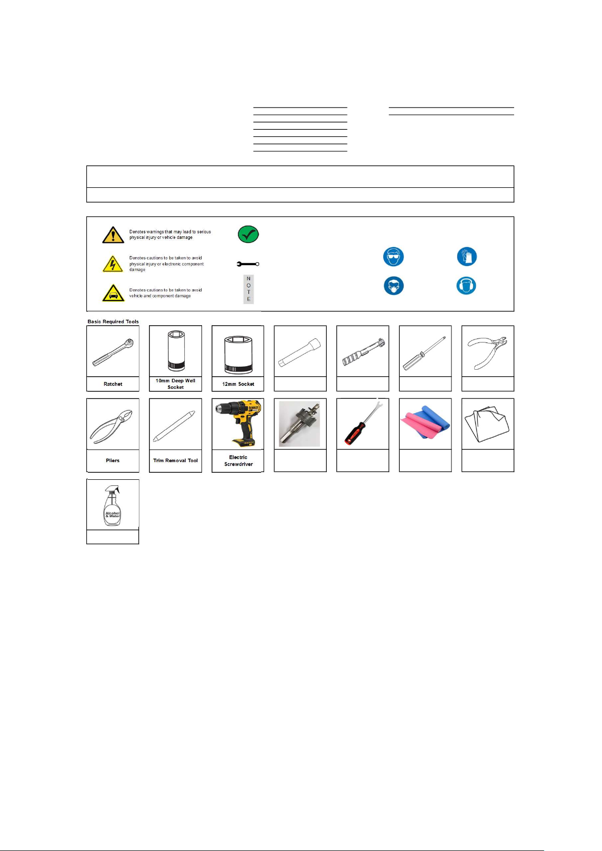
Instructional Symbols / Definitions
Denotes warnings that may lead to serious
physical injury or vehicle damage
Denotes cautions to be taken to avoid
physical injury or electronic component
damage
Denotes cautions to be taken to avoid
vehicle and component damage
Basic Required Tools
Ratchet 12mm Socket
10mm Deep Well
Socket
Denotes quality processes to be checked
prior to moving to the next step
Denotes specific tools that are necessary
to complete a step
N
O
Denotes important information to be
reviewed during the step
T
E
Extension Torque wrench Wire Cutters
Denotes personal protective equipment (PPEs) that
may be required for a step. Examples of safety
equipment icons noted below:
Glasses Gloves
Mask Hearing Protection
#2 Phillips
Screwdriver
Pliers
Clean Cloth
Technical Support
1) Read the entire Installation Instructions prior to beginning the installation of the part.
2) Make sure the vehicle is completely clean and dry in the area(s) the part is to be installed.
3) Ensure the vehicle is properly protected in the area(s) that the accessory is to be installed.
4) NEVER place tools on painted surfaces, seating surfaces, dash pad, console or floor carpet/mats.
5) Always wear appropriate personal protective equipment, including gloves, safety glasses, etc., when required.
6) Record radio presets prior to disconnecting battery power, if needed.
7) Roll down the driver's window and adjust the power seats (if applicable) prior to disconnecting battery power, if needed.
8) Vehicle should be at room temperatur e.
9)
Factory wire harness colors are subject to change, please use the specified pin # in the connector to identify the correct wires for the two T-Tap installations.
Trim Removal Tool
Electric
Screwdriver
ø26 Hole Saw
Clip Remover
보호 매트
50/50 Isopropyl
Alcohol (70%) and
Water Mix
Revision Date
04/19/2019
Page 1 of 20
Page 2
Genuine Accessories
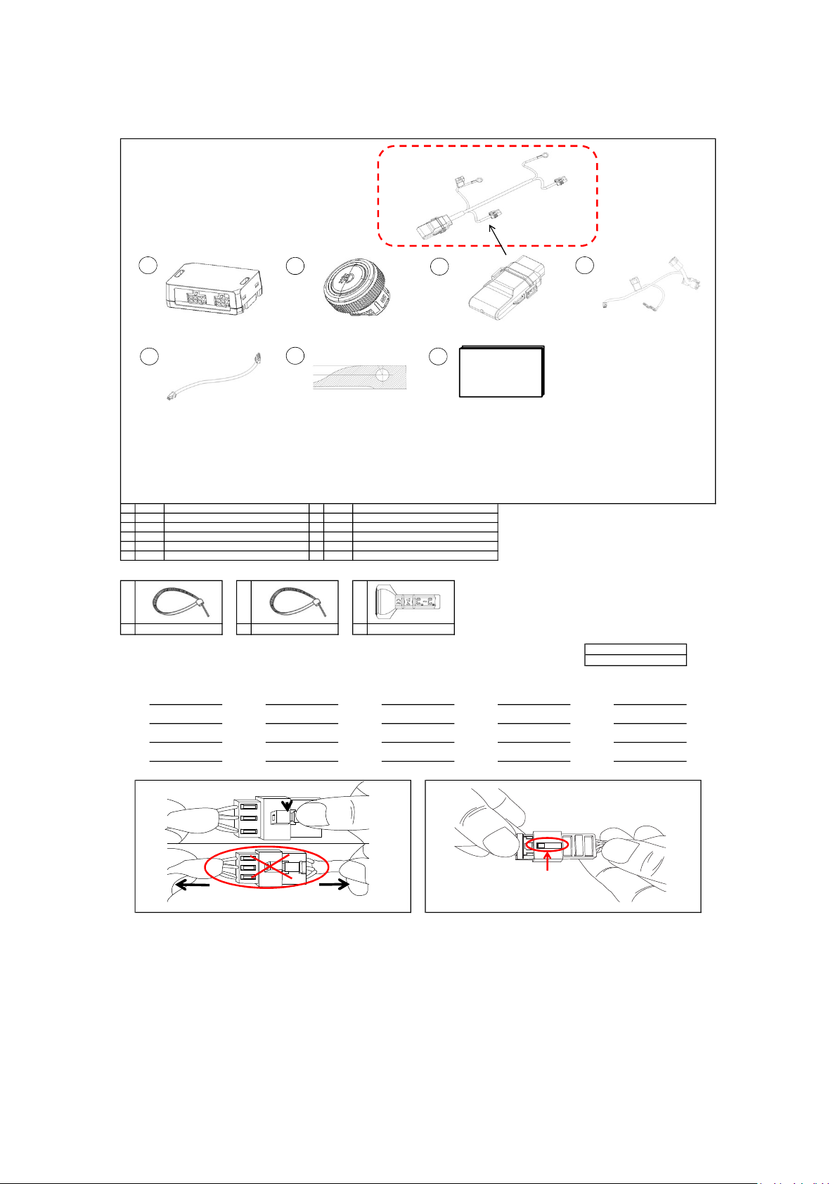
Kit Overview
CLICK
NO GOOD
5
1
2
3
4
6
7
Owner's Guide
Qty
No. No.
1
ECU Module
1 6
1 BUTTON Module
2 7
1
TRANSCEIVER Module
3 8
1
ECU Harness
4 9
1
BUTTON Harness
5 10
Hardware Kit Contents
A
7 13 3
Wire Tie(Inside)*
* Indicates extra components intentionally included in kit as spares.
Follow instructions for proper placement of each c omponent.
Radio Presets - record customer preset frequencies if disconnecting battery power
FM1
FM6
AM1
SAT1 SAT2
Special Instructions
Description
B
Wire Tie(Outside)*
FM2
FM7
AM2
1 Mylar Jig
1
Owner's Guide
C
FM3
FM8
AM3
SAT3 SAT4
DescriptionQty
T-Tap (White)*
FM4
FM9
AM4
Locking Tab
FM5
FM10
AM5
SAT5
Hardware Total
23
Disconnecting Connectors Locking Connectors
When disconnecting connectors, grasp the connectors, not the wire. When locking connectors, listen for a click indicating they are securely locked.
Revision Date
04/19/2019
Page 2 of 20
Page 3

Genuine Accessories
Confidential
Confidential
T-Tap Installation Procedure
Revision Date
04/19/2019
Page 3 of 20
Page 4
Genuine Accessories
Confidential
Confidential
Confidential
Confidential
1
A. Open the Driver's Door Window.
B. Move the Driver's Seat to the rearmost position.
C. Record all pre-set radio stations, if applicable.
N
D. Pull the Hood Lever to open the Hood.
O
T
E
3
Trim Removal Tool
2
A. Remove Negative (-) Battery Terminal Cover and store in a safe location
B. Disconnect and isolate the vehicle's Negative (-) Battery Cable.
N
O
T
E
4
Ratchet, Extension and 10mm Deep Well Socket
for reinstallation, If applicable.
WARNING! Shock Hazard. Do not touch vehicle's negative
battery terminal to vehicle's positive battery terminal. Serious
physical injury or electronic component damage may occur.
#2 Phillips Screwdriver
A. Remove the fuse panel cover.
B. Gently pull the weatherstrip back from the dash area.
C. Using a trim removal tool, remove the driver’s side dash end cap panel
N
by prying outward to disengage the four (4) pressure clips.
O
D. Store the removed parts in a safe location for reinstallation.
T
E
Caution: Do not damage the Dash Panel, Fuse Panel Cover or Dash End
Cap. Make sure no pressure clips remain in the dash board.
N
O
T
E
Revision Date
04/19/2019
A. Remove the three (3) Phillips Screws shown.
B. Store the three (3) Phillips Screws in a safe location for reinstallation.
Caution: Do not damage the Lower Dash Panel
Page 4 of 20
Page 5
Genuine Accessories
Confidential
Confidential
5
A. Using a Trim Removal Tool, release the Retaining Tab shown.
B. By hand, gently dislodge the Lower Dash Panel.
C. Disconnect OBDII Connector and any Electrical Connectors from the Lower Dash Panel, if applicable.
N
D. Store the removed part in a safe location for reinstallation.
O
T
E
6
Trim Removal Tool
Caution! Do not damage the Lower Dash Panel, OBDII Connector or Electrical Connectors.
Ratchet, Extension and 10mm Deep Well Socket
A. Remove the four (4) 10mm Bol ts securing the Knee Bolster Plate.
B. Remove the Knee Bolster Plate.
C. Store the removed parts in a safe location for reinstallation.
N
O
T
E
Warning! The Knee Bolster Plate may have sharp edges. Take necessary precautions.
Revision Date
04/19/2019
Page 5 of 20
Page 6
Genuine Accessories
Confidential
Confidential
Confidential
A. Connect the 6-Pin Fog lamp ECU Connector (black ) to the Control Module.
B. Connect the 4-Pin Fog lamp ECU Connector (black ) to the Control Module.
N
O
T
E
9
87
A. Using two (2) Wire Ties, secure the Fog ECU harness(ECU+BUTTON
B. Trim excess Wire Tie material.
N
O
T
E
Wire Cutters
Module) to the (ICU_FRNT_A, ICU_FRNT_B) Factory Harness as shown.
A.Connect the corresponding Fog lamp ECU ODB II Connector to the ODB II Connector Disconnect from Lower Dash Panel.
B. Locate the Fog lamp ECU ODB II Connector to the Lower Dash Panel, as shown above.
N
O
T
E
Revision Date
04/19/2019
Page 6 of 20
Page 7

Genuine Accessories
Confidential
Confidential
10
A. Disconnect the 32-Pin CAN Connector from the Fuse Box as shown.
B. Peel back insulation tape from the end of the connector harness, as needed, to make room for T-Taps.
C. Using Pliers, crimp the small end of the T-Tap onto the White Wire of ECU Har ness and repeat procedure for Brown Wire of ECU Harness.
D. Match the T-Taped White of ECU Harness to Blue Wire (Pin #15) of Vehicle 32-Pin CAN Connector and using pliers, crimp the large end of the T- Tap
N
O
T
E. Match the T-Taped Brown Wire of ECU Harness to Red Wire (Pin #16) of Vehicle 32-Pin CAN Connector and using pliers, crimp the large end of the T-T ap
E
F. Secure the ECU CAN harness to the factory harness with one (1) Wire Tie, as shown above, and trim excess wire tie material.
G. Reinstall the 32-Pin CAN connector into the fuse box. Ensure it is locked in place
Pliers and Wire Cutters
onto Blue Wire (Pin #15) of Vehicle 32-Pin CAN Connector.
- Refer to the T-Tap Installation Procedure on page 3.
onto Red Wire (Pin #16) of Vehicle 32-Pin CAN Connector.
- Refer to the T-Tap Installation Procedure on page 3.
Make sure to check the Correct wire Pin location for both T-Tap installations.
.
11
A. Locate ECU Module on Factory harness as shown above.
B. Using two (2) Wire Ties, secure the ECU Module to the Factory Harness as shown.
C. Using one (1) Wire Tie, secure the Fog lamp ECU harness(ECU+Button Module) to the Factory Harness as shown.
N
D. Trim excess Wire Tie material.
O
T
E
Wire Cutters
Revision Date
04/19/2019
Page 7 of 20
Page 8

Genuine Accessories
Confidential
Confidential
12
N
A. Reinstall all removed Knee Bolster Plate in reverse order of disassembly.
O
T
E
13 ø26 Hole SAW, Electric Screwdriver
Ratchet, Extension and 10mm Deep Well Socket
Warning! The Knee Bolster Plate may have sharp edges. Take necessary precautions.
A. Attach the sheet paper.
B. Hole machining at the position indicated on the sheet paper.
N
C. Remove the sheet paper.
O
D. Install the button.
T
E. Reinstall Lower Dash Panel.
F. Reinstall fuse panel cover side dash end cap panel.
E
Be carefu l that the butt ons are m ounte d in t he co rrect o rientat ion as shown .
Revision Date
04/19/2019
Page 8 of 20
Page 9

Genuine Accessories
Confidential
Confidential
Confidential
14
N
A. Open the Cap In middle of Engine room.
O
T
E
1615
N
A. Remove the a bolt inside of Cap.
O
T
E
Ratchet, Extension and 10mm Deep Well Socket
Revision Date
04/19/2019
Page 9 of 20
Page 10

17 Clip Remover
Confidential
Confidential
Confidential
A. Remove the six(6) Clips on lower bumper.
N
O
T
E
Genuine Accessories
18
N
A. Remove the three(3) Clips in Front left of tire
B. Remove the one (1) Phillips Screw in Front left of tire as shown.
O
T
E
Clip Remover, Screw driver
19
N
A. Remove the three(3) Clips in Front right of tire
B. Remove the one (1) Phillips Screw in Front left of tire as shown.
O
T
E
Clip Remover, Screw driver
Revision Date
04/19/2019
Page 10 of 20
Page 11

Genuine Accessories
Confidential
Confidential
Confidential
20 21
A. Install a protective mat on the floor.
N
B. Gently pull the left and right bumper back and dislodge the bum per by hand.
C. Unplug the Factory connector from bum per when pull bumper back, if
O
application.
T
D. Place the bumper on the protective mat.
E
To prevent damage to the bum per, two people are recommended.
N
O
T
E
22
N
A. Locate TRANSCEIVER Module to Left above of front bumper beam as shown.
B. Using three (3) Wire Ties, secure the Reciever Module to the factory harness to front bumper beam as shown.
O
C. Trim excess Wire Tie material.
T
E
Wire Cutters
Revision Date
04/19/2019
Page 11 of 20
Page 12

Genuine Accessories
Confidential
Confidential
Confidential
23
A. Using two (2) Wire Ties, secure TRANSCEIVER Harness to Factory
B. Make sure theTRANSCEIVER Harness which be connected from right of
N
O
C. Trim excess Wire Tie material.
T
E
25
Wire Cutters
harness.
vehicle is routed on back of front bumper beam.
Wire Cutters, Ratchet, Extension and 10mm Deep Well Socket
24
A. Secure the TRANSCEIVER Harness to Factory Harness using one(1) wire Tie.
B. Follow Factory Harness and connect TRANSCEIVER Harness to Fuse Box.
C. Trim excess Wire Tie material.
N
O
T
E
Wire Cutters
A. Open the fuse box cover.
B. Remove the 10mm alternator Blot.
C. Insert the 10mm alternator Bolt into the +12V Ring Terminal, and reinstall.
N
D. Using two (2) Wire Ties, secure TRANSCEIVER Harness to Factory harness.
O
E. Locate TRANSCEIVER Fuse in the Fuse box and TRANSCEIVER harness passes through the gap of Pannel.
T
F. Trim excess Wire Tie material.
E
G. Close the fuse box cover.
Be careful that the wires come out t hrough the cover hole.
Revision Date
04/19/2019
Page 12 of 20
Page 13

Genuine Accessories
Confidential
Confidential
Confidential
26
A. Using one (1) Wire Ties, secure TRANSCEIVER Harness to Factory
B. Using one (1) Wire Ties, secure TRANSCEIVER Harness to Factory Metal
N
O
C. Trim excess Wire Tie material.
T
E
Wire Cutters
Harness.
bracket in below front lamp.
27
A. Remove 12mm Bolt.
B. Insert the 12mm Bolt into the GND Ring Terminal, and reinstall.
C. Using One (1) Wire Tie, Secure TRANSCEIVER Harness to Factory
N
O
D. Trim excess Wire Tie material.
T
E
Wire Cutters, Ratchet, Extension and 12mm Deep Well Socket
Harness.
28
N
A. Remove the front bumper energy absorb er.
O
T
E
Be careful not to damage the rad iator grill when replacing the grill.
Revision Date
04/19/2019
Page 13 of 20
Page 14

Genuine Accessories
Confidential
Confidential
29
N
A. Remove twelve pieces of screws.
O
T
E
30
Electric Screwdriver
Wire Cutters
N
A. Remove the lower hook (5ea)
O
T
E
Be sure to check the hook shap e and position.
Revision Date
04/19/2019
Page 14 of 20
Page 15

Genuine Accessories
Confidential
Confidential
31
N
A. Remove the top hook (9ea)
O
T
E
32
Wire Cutters
Be sure to check the hook shap e and position.
Wire Cutters
N
A. Remove the garnish hook (small hook) (4ea)
B. Be careful not to remove the bumper hook.
O
T
E
Be sure to check the hook shap e and position.
Revision Date
04/19/2019
Page 15 of 20
Page 16

Genuine Accessories
Confidential
Confidential
33
N
A. Remove the grill.
B. Be careful not to damage the bumper .
O
T
E
34
Wire Cutters
N
A. Remove the garnish hook.
B. Be careful not to remove the bumper hook.
O
T
E
Be sure to check the hook shap e and position.
Revision Date
04/19/2019
Page 16 of 20
Page 17

35
Confidential
Confidential
N
A. Remove the garnish.
B. Fit the grill assembly.
O
T
E
Genuine Accessories
36
N
A. Tighten 4 pieces of screws.
O
T
E
Electric Screwdriver
Revision Date
04/19/2019
Page 17 of 20
Page 18

Genuine Accessories
Confidential
Confidential
37
N
A. After mounting the lamp, tighten the screws. (Left and right, each 3 EA)
O
T
E
38
Electric Screwdriver
N
A. Install the front bumper energy absorber.
O
T
E
Revision Date
04/19/2019
Page 18 of 20
Page 19

Genuine Accessories
Clip Remover, Screw driver, Ratchet, Extension and 10mm Deep
Confidential
Confidential
Confidential
Confidential
39 40
A. Connect TRANSCEIVER HARNESS to Genuine fog lamp in Bumper.
(Left, Right)
N
O
T
E
41
Ratchet, 10mm Deep Well Socket, Extension, and Torque Wrench
Well Socket
A. Reinstall all removed front bumper in reverse order of disassembly.
N
O
T
E
To pr event da mage to th e bum per, tw o pe ople are re comme nded.
42
A. Reconnect the Negative (-) Battery Cable. Torque to:
5.0 ~ 6.0 N.m (0.5 ~ 0.6 kgf.m, 45 ~ 52 lb-in).
B. Reinstall the vehicle's Negative (-) Battery Terminal Cover, if applicable.
N
C. Temporarily reinstall the weatherstrip at dash area to allow Driver's Door
O
to close properly.
T
D. Close the Hood, Tailgate and all Doors.
E
E. Test the LOCK / UNLOCK function using Factory Key Fob.
NOTE: If vehicle is not responding, carefully re-check all wiring
connections. If the vehicle is still not responding, follow the
Troubleshooting at the end of the instructions.
GO TO → Function Check
A. Perform the Function Check at the end of the Instructions.
N
O
T
E
Revision Date
04/19/2019
Page 19 of 20
Page 20

Genuine Accessories
43
Fog Lamp Operation Check.
・If the battery would be disconnected, some functions will no longer
operate.
・Turn the ignition switch to ON and check the operation of the fog lamps.
・Set the lighting control lever on the low beam position and turn the fog
light switch on, then check if the fog lights are on.
・Turn the fog light switch on, and check if the fog light indicator light in
the instrument cluster is illuminated.
・Turn the fog light switch off, and check if the fog light indicator light
turns off.
・If the fog light does not work properly, the indicator flashes 3 times.
Light and Fog Lamp condition table.
N
O
T
E
45
FCC COMPLIANCE
Part 15.19
This device complies with Part 15 of the FCC Rules. Operation is subject to the
following two conditions:
(1) this device may not cause harmful interference, and
(2) this device must accept any interference received, including interference that
may cause undesired operation.
Part 15.105
This equipment has been tested and found to comply with the limits for a Class B digital device,
pursuant to part 15 of the FCC Rules. These limits are designed to provide reasonable
protection against harmful interference in a residential installatiom This equipment generates,
uses and can radiate radio frequency
energy and, if not installed and used in accordance with the instructions, may cause harmful
interference to radio communications. However, there is no guarantee that interference will not
occur in a particular installation. If this equipment does cause harmful interference to radio or
television reception, which can be determined by turning the equipment off and on, the user is
encouraged to try to correct the interference by one or more of the following measures:
Reorient or relocate the receiving antenna.
Increase the separation between the equipment and receiver.
Connect the equipment into an outlet on a circuit different from that to which the receiver is
connected.
Consult the dealer or an experienced radio/TV technician for help.
Part 15.21
Changes or modifications not expressly approved by the party responsible for compliance
could void the user's authority to operate the equipment.
RF exposuree (20 cm over)
This device should be installed and operated with minimum 20 cm between the radiator and
your body.
44
CAUTION
Heed the following cautions when handling (maintenance) the wireless fog lamp kit.
・If gasoline, dissel, oil, engine coolant, or battery fluid adheres to the hard
plastic parts, it will cause discoloration, stains, or damage.
Wipe off immediately with a soft cloth.
・Depending on the type of high pressure car washer used, the water for
washing may be high temperature and/or under high pressure.
Be careful when using pressurized water from a car washer nozzle.
If the nozzle is too close or water pressure is applied for long periods,
it may cause deformation or damage to the hard plastic parts.
・Do not use electric or air tools to apply wax or compound (polishing
powder). Otherwise, friction heat will be generated causing
deformation or damage to the hard plastic parts.
N
O
T
E
46
IC COMPLIANCE
GEN 8.4
This device complies with Industry Canada license-exempt RSS standard(s).
Operation is subject to the following two conditions:
(1) this device may not cause interference, and
(2) this device must accept any interference, including interference that may
cause undesired operation of the device.
Le présent appareil est conforme aux CNR d’Industrie Canada applicables aux
appareils radio exempts de licence. L’exploitation est autorisée aux deux
conditions suivantes :
(1) l’appareil ne doit pas produire de brouillage, et
(2) l’utilisateur de l’appareil doit accepter tout brouillage radioélectrique subi,
même si le brouillage est susceptible d’en compromettre le fonctionnement.
RF exposuree (20Cm over)
This equipment should be installed and operated with minimum 20 cm between
the radiator and your body.
Cet appareil doit étre installé et utilisé avec un minimum de 20 cm entre le
radiateur et votre corps.
N
O
T
E
N
O
T
E
Revision Date
04/19/2019
Page 20 of 20
 Loading...