

Page 1

FT-KL1
Installation Manual
Version: 1.0
Page 2
2
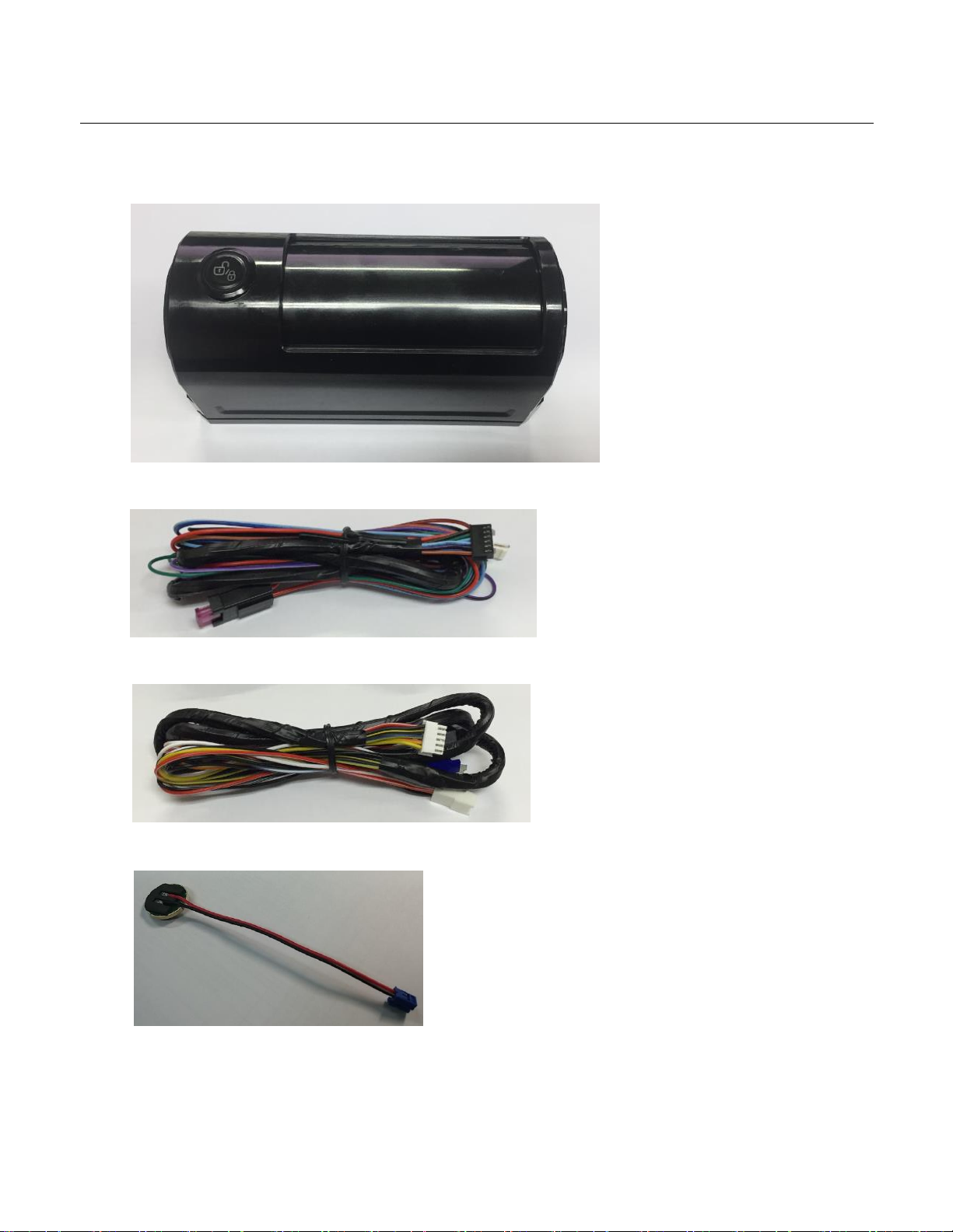
Kit(s) Contents
The Key Locker controller includes all your basic components for basic install.
• Key Locker x 1EA
• CN1 Harnesses x 1EA
• CN2 Harnesses x 1EA
• Coin Dummy Battery x 1EA
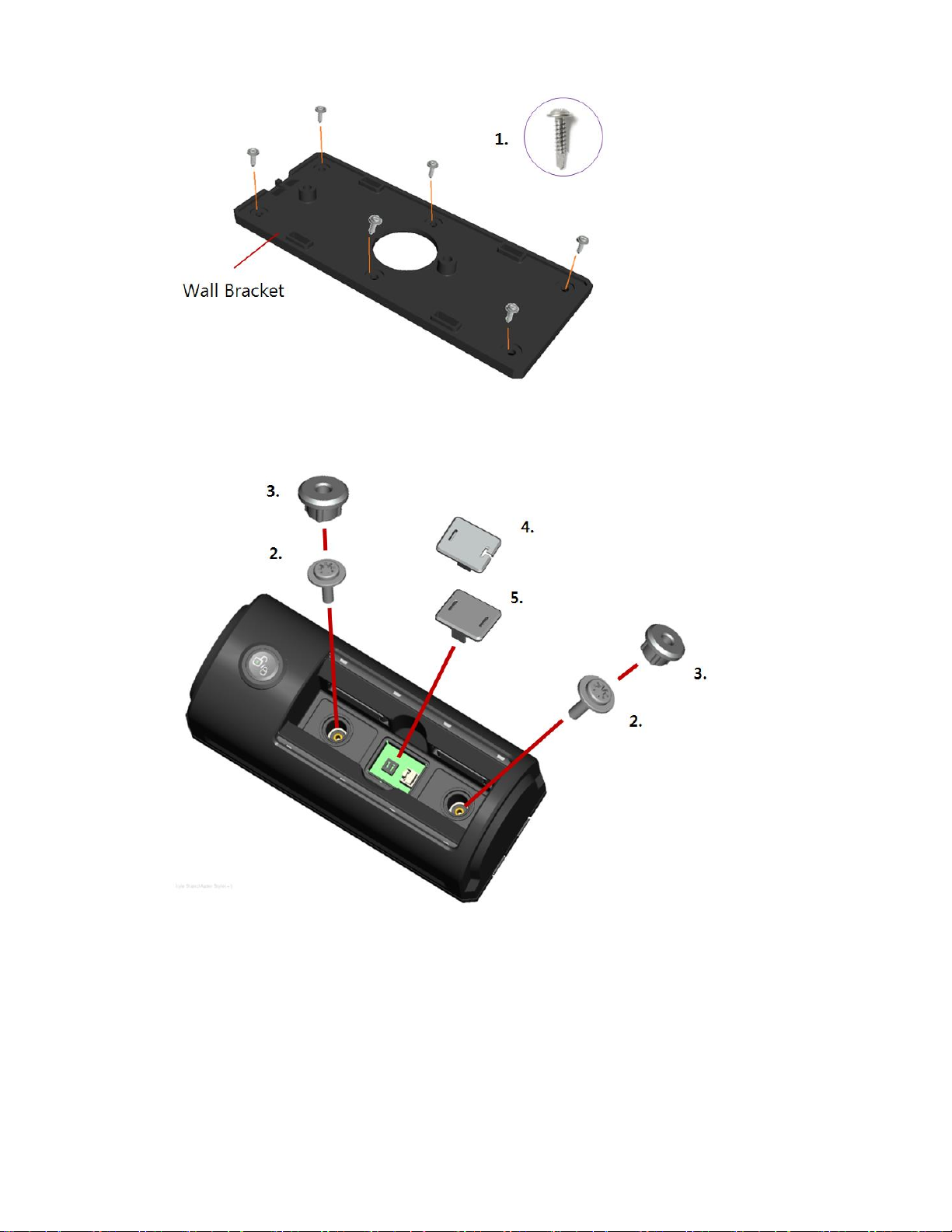
• Accessory Parts
1. Self Drilling Screw x 6EA
Page 3
3
2. Star Head Screw x 2EA
3. Rubber Cap x 2EA
4. Rubber Pad (POWER) x 1EA
5. Rubber Pad (RF) x 1EA
RF Kits with remote(s), Antenna, and Antenna Cable are not included with the Key Locker controller
kit. The remote(s) and antenna are modular and are not specific to the control modules. You can pair
almost any Firstech remote(s) and antenna receiver to the Key Locker control module.
Page 4

4
Installation Basics
If you are new to installing Firstech alarm units, we recommend that you review this manual in its entirety
prior to installing your first unit.
Key Points to Consider Before Installation:
New Option Menus
The new option menu differs completely from other Firstech systems. It is important to familiarize
yourself with these as it will save time in most applications.
Option Programmer (FT-OP500)
Most options on this unit can be programmed with the remote(s) as well as the Option Programmer
(OP500). Please note the system must be disarmed before connecting the OP500. Otherwise, an
“ERROR” message will show on the display of your OP500.
Page 5

5
Remote Programming Routine
IMPORTANT: The remotes are preprogrammed to the control module. If you need to program the
remotes, follow the instructions below.
Programming the Remote
STEP 1: Activate Programming mode by turning the ignition key on and off (between the Acc & On
positions) five times within 10 seconds. The vehicle’s parking lights will flash once with the successful
completion of this step.
STEP 2: Within a second after cycling the ignition the 5th time, tap the Lock button on the remote for a
half second. The parking lights will flash once to confirm the transmitter has been coded.
Programming Multiple Remotes: After the confirmation flash given
in STEP 2, you can code additional remotes by tapping the Lock
button on the remote(s). The parking lights will flash once confirming
each additional remote. The Key Locker can store up to 4 remotes.
Exiting Programming: Programming is a timed sequence. The
parking lights will flash twice signaling the end of programming mode.
R
emote programming procedure:
PTS
(Push
to Start Vehicles
)
Application
STEP
1: Set the vehicle to the ignition or “ON” position
STEP
2:
Within
5 seconds push to the “OFF” position
STEP
3:
Within
5 seconds set the vehicle to the ignition or “ON” position (do not start)
STEP
4: Step on the foot brake 3 times
within
5 seconds *parking lights
will
flash 1 time to indicate
remote
programming is
enabled
STEP
5: Tap
(a quick 0.5 second press and release) the lock button on the remote * the
parking lights will flash 1 time indicating the remote code has been
accepted
STEP
6:
After
10 seconds of no valid remote codes being transmitted the Key Locker
will
automatically exit programming mode
Note:
If no
valid remotes are
programmed
the Key Locker will enter
valet mode.
Page 6

6
Placement and Use of Components
IMPORTANT: The placement and use of components are critical to the performance of this system.
Antenna and Cable
Firstech antennas are calibrated for horizontal installation at the top of the windshield. It does not have to
be mounted in the top left corner as shown to the left. The cable that connects the antenna to the brain
must be free from any pinches or kinks. Installing the antenna in areas other than the windshield may
adversely affect the effective transmitting distance of the remotes.
FT-TP1(Remote Paging Sensor)
The FT-TP1 has multiple features including: remote paging, 4-digit pin unlock/disarm, and arm/
lock. All features are operated with a simple touch of the sensor.
FT-TP1 functions do not require programming.
NOTE: If you enter the wrong code more than 5 times within 30 minutes the TP1 function will be
disabled for 1 HOUR.
Alarm rearm and lock
To rearm hold your finger on the ‘Red Circle’ for 3 seconds.
Alarm disarm and unlock
To disarm hold your finger over the ‘Red Circle’ for 3 seconds. Once the LEDs start their circular pattern,
enter your 4-digit code by touching the window with the flat part of the tip of any finger over the number
for each digit of your code. (Refer to Step 4 above or training video at www.firstechdata.com) Two
seconds after entering the 4th digit, your system will first re-arm/lock. In two seconds, it will disarm/
unlock.
2 Way LCD remote paging
To page a 2 Way LCD remote, hold your finger over the ‘Red Circle’ twice.
Touch Panel Sensitivity
To change touch sensitivity, open the driver’s door, hold the button on the back of the TP1 until the LEDs
go out. Release button and tap again. The number of solid LEDs represent sensitivity of touch, 1 being
the lowest, 5 the highest.
Common Procedures
Valet Mode
When servicing or loaning your vehicle to others, your Key Locker system should be placed in Valet
Mode. Valet Mode disables all alarm functions.
IMPORTANT: While in Valet mode the Key Locker will still lock and unlock power lock systems.
The system can be put into valet one of two ways:
1. Turn the vehicle’s key to the ignition “on” position and tap the Lock and Trunk buttons
simultaneously for a half second. The parking lights will flash once to confirm the system is in
Valet Mode. Repeat this process to take the system out of Valet Mode. Ignition does not have to
Page 7
7
be on. Upon holding the same buttons again the parking lights will flash twice to confirm the
system is out of Valet Mode.
2. You can put the system into Valet by holding the foot brake(data input only) and then
turning the ignition key “on” and then “off” five times within 10 seconds. The parking
lights will flash once to confirm the system is in Valet Mode.
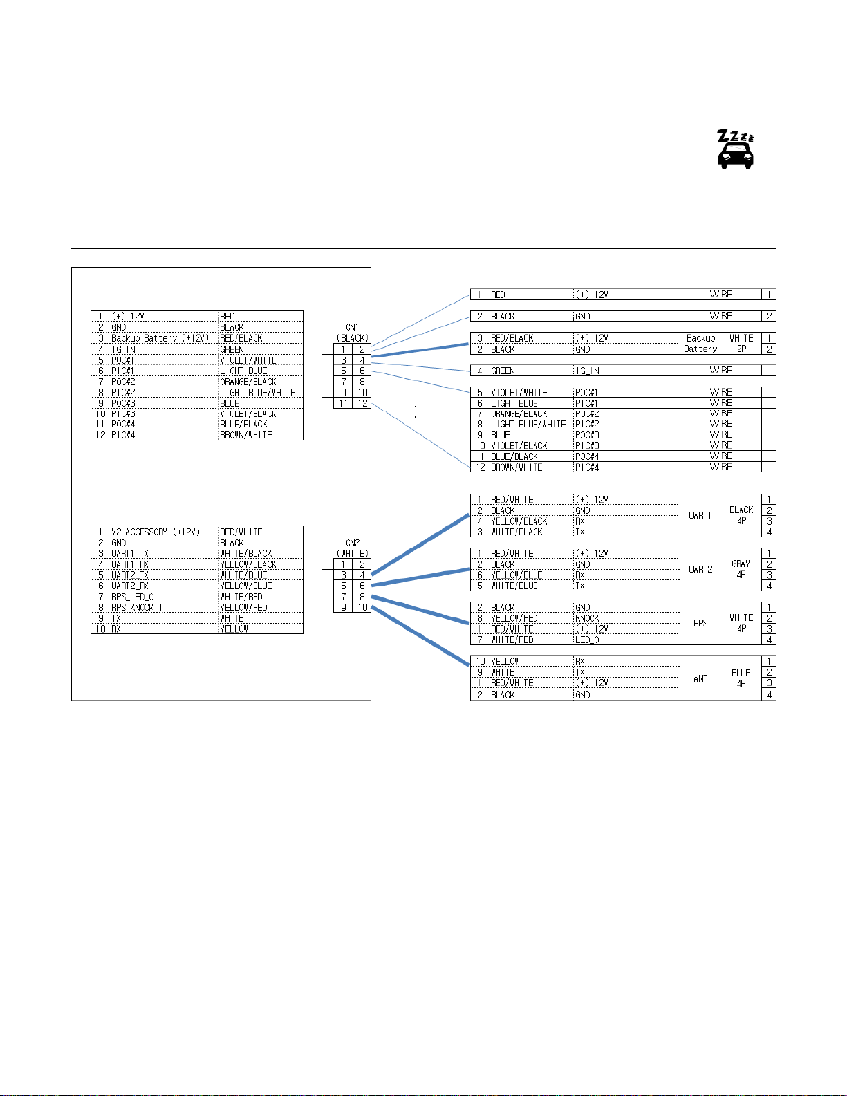
Key Locker Wiring Schematic
Connector 1 (CN1), Black 12-Pin Harness
Pin 1 Red - Constant 12V positive (+) power input. This wire must be connected. The proper vehicle
wire will test (+) 12V at all times - while the key is in the off position, the on position and during
crank.
Pin 2 Black - Ground negative (-) input. This wire must be connected to the vehicle’s ground.
Pin 3 Red/Black – Constant 12 V positive (+) input and (+) charging output.
Pin 4 Black - Ground negative (-) input.
Pin 5 Violet/White - [POC 1] Starter Kill 250mA latched negative (-) output. Note: There are additional
POC setting options for this POC.
Page 8

8
Pin 6 Light Blue - [PIC 1] Door (default setting) negative (-) programmable input. There are additional
options for this PIC. Please see Special Options Group 3.
Pin 7 Orange/Black – [POC 2] Horn 250mA negative (-) output. There are additional POC setting
options for this POC.
Pin 8 Light Blue/White - [PIC 2] Trunk (default setting) negative (-) programmable input. There are
additional options for this PIC. Please see Special Options Group 3.
Pin 9 Blue - [POC 3] Lock 250mA, 800mS (-) negative output. There are additional POC setting options
for this POC.
Pin 10 Violet/Black - [PIC 3] Arm (default setting) negative (-) programmable input. There are additional
options for this PIC. Please see Special Options Group 3.
Pin 11 Blue/Black - [POC 4] Unlock 250mA, 800mS (-) negative output. There are additional POC
setting options for this POC.
Pin 12 Brown/White - [PIC 4] Disarm (default setting) negative (-) programmable input. There are
additional options for this PIC. Please see Special Options Group 3.
Connector 2 (CN2), White 10-Pin Connectors
Black 4-Pin (UART Data Port) ADS data to data only
This connector is used for updating control modules via www.firstechdata.com.
This port provides simple connectivity of iDatalink modules.
Pin 1 Red/White - 12V positive (+) output.
Pin 2 Black - Ground (-) output.
Pin 3 Yellow/Black - RX Input, this wire receives data
Pin 4 White/Black - TX Output, this wire transmits data
Grey 4-Pin (UART Data Port) Drone data to data only
Pin 1 Red/White - 12V positive (+) output.
Pin 2 Black - Ground (-) output.
Pin 3 Yellow/Blue - RX Input, this wire receives data.
Pin 4 White/Blue - TX Output, this wire transmits data.
White 4-Pin (Pre-wired FT-TP1)
Pin 1 Black - Ground (-) output.
Pin 2 Yellow/Red - Negative (-) paging input.
Pin 3 Red/White - 12V positive (+) output.
Pin 4 White/Red - 9V positive (+) L.E.D. output.
BLUE 4-Pin to 4-Pin or 6-Pin (Pre-wired Antenna Cable)
Connect your antenna cable to this port. You can only use 4 to 4 pins or 4 to 6 pin antenna cables.
Pin 1Yellow - RX input. This wire receives the signal from remote.
Pin 2 White - TX output. This wire transmits the signal to remote.
Pin 3 Red/White - 12V positive (+) output.
Pin 4 Black - Ground (-) output.
Page 9

9
Option Programming Tables
OPTION GROUP #1
#1
Feature
Setting
Default(I)
Optional(II)
Optional(III)
Optional(IV)
1-2
Lock / Unlock pulse duration.
0.8 sec
2.5 sec
0.125 sec
3.5 sec
1-3
Driver's priority unlock
Off
On
1-4
Double pulse unlock.
Off
Unlock
Lock
Both Lock and Unlock
1-7
Unlock / Disarm With Trunk Release
Unlock, Factory Disarm,
and Trunk Release
Factory Disarm,
Trunk Release Only
Trunk Release Only
1-8
Locking while in Passive Arming
Off
Passive locking
w/ Passive Arming
No Passive Locking
w/ Passive Arming
1-10
Auto Relock (If a door is not opened
within this amount of time.)
Off
30 sec
60 sec
5 min
1-11
Ignition / Accessory Out Upon Unlock
Off
Ignition Pulse-same timing
as disarm pulse
Acc Pulse-same timing
as disarm pulse
Ig and Acc Pulse-same
timing as disarm pulse
1-13
Double pulse disarm
Standard
Double Pulse
1-15
Trunk Output Timing
1sec
2 sec
3 sec
4 sec
1-16
Horn Mute Control on Remote
Disabled
Enabled
OPTION GROUP #2
#2
Feature
Setting
Default(I)
Optional(II)
Optional(III)
Optional(IV)
2-1
Key Locker Type
RF Shield Type
Coin Battery Type
2-2
Key Locker RF Shielding Time
When LF detection of Vehicle
60 sec
30 sec
20 sec
10 sec
2-3
Key Locker 'Roof Lock'
Disabled
Enabled
OPTION GROUP #3
#3
Feature
Setting
Default(I)
Optional(II)
Optional(III)
Optional(IV)
3-2
Confirmation Horn
Medium (30mS)
Short (15mS)
Normal (60mS)
3-3
Dome Light Delay
Off
5 sec
45 sec
Auto
3-4
Starter-Kill relay.
Anti-Grind + Starter Kill
Anti-Grind
Anti-Grind + Passive
Starter Kill
3-5
Anti-Jacking
Starter-kill
Ignition-Kill (no Anti-Grind)
Page 10

10
3-6
Factory Alarm Option
On
Off
3-7
Horn Duration (Upon Alarm Trigger)
30 sec
60 sec
120 Sec
Horns for 20 seconds
3-8
Horn Output
On Double Lock Only
On Lock and Unlock
3-15
Soft Disarm
Off
On
Disarm 1 Press
OPTION GROUP #4
#4
Feature
Setting
Default(I)
Optional(II)
Optional(III)
Optional(IV)
4-1
Aux 1 output
0.5sec
Latch
0.5 sec Pulse + Program
Program
4-2
Aux 2 output
0.5sec
Latch
0.5 sec Pulse + Program
Program
4-3
Aux 1 output Control
By Remote
Arm
Disarm
Input Trigger
4-4
Aux 2 output Control
By Remote
Arm
Disarm
Input Trigger
4-14
Low Battery Warning
OFF
ON (at 11.7 Volts)
SPECIAL OPTION GROUP #1
S-#1
Feature
Setting Value
1
AUX1 output time
1 ~ 99 [seconds], LA(Latch), 1~15 [minutes]
2
AUX2 output time
1 ~ 99 [seconds], LA(Latch), 1~15 [minutes]
SPECIAL OPTION GROUP #2
S-#2
Feature
Setting Value
Programmable Output Connector
Optional
1
POC #1 (Default : Starter Kill)
2nd LIGHT [ 1 ]
Aux1 [ 10 ]
Deleted
Starter Kill [ 29 ]
2
POC #2 (Default : Horn)
Deleted
Aux2 [ 11 ]
chirp-2 [ 20 ]
3
POC #3 (Default : Lock)
2nd IG1 [ 3 ]
Deleted
Deleted
4
POC #4 (Default : Unlock)
2nd ACC [ 4 ]
Deleted
Deleted
Deleted
Deleted
Deleted
REARM [ 6 ]
Deleted
Lock [ 25 ]
DISARM [ 7 ]
Deleted
Unlock [ 26 ]
HORN [ 8 ]
Deleted
Priority Unlock [ 27 ]
Page 11

11
DOME LIGHT [ 9 ]
GWA [ 18 ]
Trunk Release [ 28 ]
SPECIAL OPTION GROUP #3
S-#3
Feature
Setting Value
Programmable Input Connector
Optional
1
PIC #1 (Default: (-) Door Input)
(-) E- Brake Input [1]
(-) Disable Arm/Disarm
when Wire triggered Same
Time [ 8 ]
(-) Arm Input [15]
2
PIC #2 (Default: (-) Trunk Input)
(-) Trunk Input [2]
(N/C) Trunk Input [9]
(-) Disarm Input [16]
3
PIC #3 (Default: (-) Arm Input)
(-) Key Sense Input [3]
(N/C) Key Sense Input [10]
(-) IGN & Sensor Bypass
Input [17]
4
PIC #4 (Default: (-) Disarm Input)
(-) Hood Input [4]
(N/C) Hood Input [11]
(-) AUX 1 trigger input [18]
(-) Door Input [5]
(N/C) Door Input [12]
(-) AUX 2 trigger input [19]
Deleted
(-) Pre-warn Input [13]
Deleted
(-) Instant Trigger Input
[14]
*Once programmed, this feature requires activation from the remote. Please refer to the
remote user manual or the option description below.
Option Menu Descriptions
1-02 Lock / Unlock Pulse Duration: This does not affect the behavior of the factory arm output
(orange wire) or factory alarm disarm output (orange/white wire).
FO1 - 0.8 seconds: (-) Negative lock and unlock output time.
FO2 - 2.5 seconds: (-) Negative lock and unlock output time.
FO3 - 0.125 seconds: (-) Negative lock and unlock output time. This option may be helpful when
using lock/unlock to arm/disarm vehicles that may roll windows down with factory Arm/Disarm
wires when the standard output is too long.
FO4- 3.5 seconds: (-) Negative lock and unlock output time.
1-03 Driver’s Priority Unlock: FO1 - Off: (default)
FO2 - On: This feature will allow the user to unlock the driver’s door first. If the unlock button is
pressed again within 4 seconds, the other doors will unlock. The driver’s door unlock must be
isolated from the other doors and use the blue (-) unlock. The Orange/Black (-) 2nd unlock (POC
setting) is used to provide unlock output to unlock all other doors.1-04
1-04 Double Pulse Unlock: FO1 - Off: (default)
FO2 - Unlock: This option will provide a double pulse output only for unlock each time the Key
Locker executes the unlock command. (Length of output time will be based on feature 1-02 option
settings.)
Page 12

12
FO3 - Lock: This option will provide a double pulse lock output only for lock each time the Key
Locker executes the lock command. (Length of output time will be based on feature 1-02 option
settings.)
FO4 - Lock and unlock: This option will provide a double pulse lock output for both lock and
unlock each time the Key Locker executes lock or unlock commands. (Length of output time will be
based on feature 1-02 option settings.)
1-07 Unlock/Disarm With Trunk Release: FO1 - Unlock, Factory Alarm Disarm (FAD) trunk
release: This option will send unlock and FAD outputs prior to sending the Trunk release output.
This applies to analog and data to data situations.
FO2 - Factory Alarm Disarm (FAD) with trunk release: This option will send the FAD output
prior to sending the trunk release output. This applies to analog and data to data situations.
FO3 - Trunk release only: This option will only send the trunk release output when triggered. This
applies to analog and data to data situations.
1-08 Locking While in Passive: When options 2 or 3 are selected the user has the choice to
activate “Passive” feature using a Firstech remote or Drone (please check specific remote
user’s manual for steps to activate passive)
FO1 - Off: (default)
FO2 - Passive locking with passive arming: This option, when passive is activated will send
lock/arm outputs to lock/arm the Key Locker 30 seconds after the last zone is closed. The Key
Locker will flash the parking lights the horn 1 time every 10 seconds 3 times total as a warning that
it is going to Arm/lock itself.
FO3 - No lock output with Passive arm: This option, when passive arm feature is activated, will
NOT send the lock command one the Key Locker has passively armed itself. The Key Locker will
flash the parking lights the horn 1 time every 10 seconds 3 times total as a warning that it is going
to arm itself.
1-10 Auto Relock (If Door is not Opened Within Set Time)
FO1 - Off: (default)
FO2 - 30 seconds: This option allows the Key Locker to automatically relock/rearm 30 seconds
after Key Locker has been disarmed/unlocked. This will only happen if no zones have not been
opened.
FO3 - 60 seconds: This option allows the Key Locker to automatically relock/rearm 60 seconds
after Key Locker has been disarmed/unlocked. This will only happen if no zones have not been
opened.
FO4 - 5 minutes: This option allows the Key Locker to automatically relock/rearm 5 minutes after it
has been disarmed/unlocked. This will only happen if no zones have not been opened.
1-11 Ignition + Accessory Pulse with Disarm: FO1 - Off: (default)
FO2 - Ignition (+) and (-) pulse output with disarm: This option will pulse both (+) and (-) ignition
wires upon unlock/disarm. Most new Ford vehicles require ignition pulsed + immobilizer with
unlock to disarm the factory alarm.
FO3 - Accessory (+) and (-) pulse output with disarm: This option will pulse both (+) and (-)
accessory wires upon unlock/disarm.
FO4 - Ignition (+) and (-) pulse and Accessory (+) and (-) pulse output with disarm: This
option will pulse both (+) and (-) ignition and accessory wires upon unlock/disarm. Some new Ford
vehicles require ignition and accessory pulsed + immobilizer with unlock to disarm the
factory alarm. Important: Also used in cases where the vehicle’s radio may turn on and stay on
until the door is opened when accessory is pulsed.
Page 13

13
1-13 Double Pulse Disarm: This feature enables the FAD output. It will pulse 2 times with a single
disarm command. FO1 - Off (default): Standard single pulse output on the FAD wire.
(orange/white by default)
FO2 - On: This feature will generate a double pulse output on the FAD wire. (orange/white by
default)
1-15 Trunk Output Timing: This feature determines the length of output time for the (+) or (-) analog
trunk release wire.
FO1 - 1 Second: (default) Will provide a 250mA (-) negative output for 1 second on any POC that
is programmed for trunk release or setting 28.
FO2 - 2 Seconds: Will provide a 250mA (-) negative output for 2 seconds on any POC that is
programmed for trunk release or setting 28.
FO3 - 3 Seconds: Will provide a 250mA (-) negative output for 3 seconds on any POC that is
programmed for trunk release or setting 28.
FO4 - 4 Seconds: Will provide a 250mA (-) negative output for 4 seconds on any POC that is
programmed for trunk release or setting 28.
1-16 Horn mute control: this feature allows the installer to enable or disable the horn mute
control. The mute feature will silence the horn during arm, disarm from the Firstech remote.
FO1 - Disabled: (default) will not allow for the Firstech remote to mute the horn output.
FO2 - Enabled: this feature will allow the end user to activate or deactivate the horn mute control.
2-01 Key Locker : Key Locker Type can be selected..
FO1 - RF Shield Type: (default) It operates as RF shield type.
FO2 - Coin Battery Type: It operates as Coin Battery Type. In other words, RF Shield does not
work..
2-02 Key Locker RF Shielding Time : When option 2-1-1 is set, it is possible to determine the time for
RF Shield to operate when LF emission of vehicle is detected.
FO1 – 60 sec: (default) When LF transmission of vehicle is detected, RF Shield (LF Jamming) is
output continuously for 60 seconds.
FO2 – 30 sec: When LF transmission of vehicle is detected, RF Shield (LF Jamming) is output
continuously for 30 seconds.
FO3 – 20 sec: When LF transmission of vehicle is detected, RF Shield (LF Jamming) is output
continuously for 20 seconds.
FO4 – 10 sec: When LF transmission of vehicle is detected, RF Shield (LF Jamming) is output
continuously for 10 seconds.
2-03 Key Locker 'Roof Lock' : You can decide whether to lock the key locker.
FO1 – Disable: (default)
FO2 – Enable
3-02 Confirmation Horns: This feature will allow the user to select a shorter horn output time to
simulate a quieter arm/disarm output.
FO1 - 30mS: This is a 30 milliseconds horn output with arm, disarm confirmation horns. It will
produce a “medium” volume sound. (Softer than the standard 60mS output)
FO2 - 15mS: This is a 15 milliseconds horn output with arm, disarm confirmation horns. It will
produce a “short” or quiet volume of sound. (Significantly softer than the standard 60mS output)
Page 14

14
FO3 - 60mS: This is a standard 60 milliseconds horn output with arm, disarm confirmation horns.
3-03 Dome Light Delay: This option is used when connecting the door trigger input to the vehicles
dome light circuit. It delays the door trigger input to prevent the door open icon displaying on 2 Way
remotes upon lock/arm.
FO1- Off: (default)
FO2 - 5 seconds: This option will delay the door trigger input for 5 seconds when arming the
system to account for any vehicle dome light output delay.
FO3 - 45 seconds: This option will delay the door trigger input for 45 seconds when arming the
system to account for any vehicle dome light output delay.
FO4 - Auto: This option will allow the Key Locker to wait for a change in polarity on the door input
circuit, after the system has been armed, to monitor for security.
3-04 Starter-Kill: This option determines the operation of the GWA wire (Any POC on CN3) Must be
programmed on Special Option Group #2.
FO1 - Anti grind + Starter interrupt: this option will allow the GWA to provide a negative output
when the system is armed or remote started. This will enable a starter interrupt to prevent the
vehicle from being started with the key when in an armed state.
FO2 - Anti Grind only: This option will allow GWA to provide a negative output when the system
is armed. This will enable starter interrupt and prevent the user from grinding the starter during the
takeover procedure.
FO3 - Anti Grind and passive starter interrupt: This option will allow for GWA to provide a
negative output when the system is remote started or the passive starter interrupt is engaged. This
will prevent the user from grinding the starter during the takeover procedure and enable starter
interrupt 60 seconds after the ignition has been turned off.
3-05 Anti-Jacking: this requires the starter-kill relay to be wired to the ignition vs. the starter wire
This feature will allow the Key Locker to interrupt the ignition wire if panic mode is activated while
the vehicle is running with the key.
FO1 - Off: (default) anti-carjacking feature is not enabled and the starter interrupt will operate
based on feature 3-04 option setting.
FO2 - On: this option will enable the anti-carjacking feature. Make sure the starter interrupt relay is
wired to interrupt the vehicle’s ignition wire, so the feature will operate as described. While the
vehicle is running with the key and the panic mode is activated using any Firstech 4 button or 2way LCD remote, the key Locker will enable the ignition interrupt relay so the vehicle cannot be restarted. Note: When using ignition-kill on manual transmission vehicles feature 3-04 must be set to
option 2 will need to be utilized. this disables the anti-grind circuit while the vehicle is remotestarted; if the anti-grind circuit is active and the start-kill relay is installed in the ignition, the relay
will“ buzz” while remote-started.
3-06 Security Features: This feature will enable or disable the security features of the Key Locker.
Security features include sensor inputs, zone inputs (unless using with manual transmission), horn
output. Basic features will function normally (lock, unlock, trunk release, remote start,
parking lights.) Please note the control module model when determining the correct feature option.
FO1 - On: Depending on the Control Module this option will enable the security features.
FO2 - Off: Depending on the Control Module this option will disable the security features.
3-07 Horn Duration Upon Alarm Trigger: this feature changes the duration of the horn during
full alarm.
FO1 - 30 seconds: this option will provide 30 seconds of output (+) on the horn during full alarm.
FO2 - 60 seconds: this option will provide 60 seconds of output (+) on the horn during full alarm.
FO3 - 120 seconds: this option will provide 120 seconds of output (+) on the horn during full alarm.
Page 15

15
FO4 - Horns for 20 seconds: this option will provide 20 seconds of pulsed output (+) on the
horn during full alarm.
3-08 Horn Output: This feature controls the horn output behavior during Arm, Disarm (POC setting #8)
FO1 - On double lock only: (default) this option is designed to simulate a factory keyless entry
system by providing a horn output pulse (based on the option selection of feature 3-02) each time
the lock command is sent a second time within 8 seconds of the first lock command.
FO2 - On lock and Unlock only: this option will provide a horn output pulse (based on the option
selection of feature 3-02) with each lock or unlock confirmation.
3-15 Soft Disarm: this feature will enable Factory Alarm Arm (FAA) and Factory Alarm Disarm (FAD)
outputs to trigger when silencing the horn when sounding with full alarm.
FO1 - Off: (Default) this will keep the standard soft disarm operation. Soft disarm feature
allows the user to silence the horn as its sounding with full alarm without fully disarming
the system which may unlock the doors and leave the vehicle unsecure.
FO2 - On: this option will provide a FAD output on both data and analog connections, when the
user taps the unlock/disarm once to silence the system while it’s sounding, so it will disarm
any factory alarm that may be sounding as well. In case the FAD function unlocks the doors the
Key Locker will send the FAA on both data and analog connections 5 seconds later to make sure
the vehicle is re-locked and secure. (This feature works well with GM, Chrysler, Dodge, Jeep,
Toyota, Lexus vehicles that may have factory security.)
4-01 Aux 1 Output: This feature determines the duration of the auxiliary 1 output. (Option 4 allows the
output duration to be set for a specific length of time 1-99 sec. and 1-15 min (with OP500 update
only) (Specific time setting only available when using the OP500)
FO1 - 500mS: This option will provide a (-) negative output for 500 milliseconds (Half second)
output on any POC programmed with setting 10 (AUX 1)
FO2 - Latched: This option will provide a latched (-) negative output on any POC programmed
with setting 10 (AUX 1). Note: This will stay latched until AUX 1 command is sent again to
shut it off.
FO3 - 500mS pulse + programmable timed output: This option will provide a (-) negative output
for 500 milliseconds (0.5 seconds) output on any POC programmed with setting 10 (AUX 1). It will
pause for 250 milliseconds then provide a timed output (based off of feature 4-01 option 4). Note:
in order to program the timed output the user must change feature 4-01 to option 4, then adjust
AU1 (AUX programmable output time) to desired time. To complete the programming steps feature
4-01 must be changed to option 3. I.e. 0.5 second pulse…pause…10 second pulse, this option can
be used to roll windows up or down on a vehicle that requires a similar action using the driver’s
door key cylinder.
FO4 - Program: This option allow the AUX output time to be programmed for a duration between
1-99 seconds. Note: with an OP500 update there will be additional time duration between 1-15
minutes available.
4-02 Aux 2 Output: This feature determines the duration of the auxiliary 2 output. (Option 4 allows the
output duration to be set for a specific length of time 1-99 sec. and 1-15 min (with OP500 update
only) only available when using the OP500)
FO1 - 500mS: This option will provide a (-) negative output for 500 milliseconds (0.5 seconds)
output on any POC programmed with setting 11 (AUX 2)
Page 16

16
FO2 - Latched: This option will provide a latched (-) negative output on any POC programmed
with setting 11 (AUX 2). Note: This latched output will reset when ignition is turned on.
FO3 - 500mS pulse + programmable timed output: This option will provide a (-) negative output
for 500 milliseconds (0.5 seconds) output on any POC programmed with setting 11 (AUX 2). It will
pause for 250 milliseconds then provide a timed output (based off of feature 4-02 option 4). Note:
in order to program the timed output the user must change feature 4-02 to option 4, then adjust
AU2 (AUX programmable output time) to desired time. To complete the programming steps feature
4-01 must be changed to option 3. (i.e. half second pulse…pause…10 second pulse) This option
can be used to roll windows up or down on a vehicle that requires a similar action using the
driver’s door key cylinder.
FO4 - Program: This option allows the AUX output time to be programmed for a duration between
1-99 seconds. Note: The OP500 must be updated for additional time duration settings. (1-15
minutes available)
4-03 Aux 1 Output Control: This feature allows the user to configure the method of which Auxiliary 1
can be activated.
FO1 - Remote: (default) This option allows AUX 1 (output time based on feature 4-01) to be
triggered by any 4 button Firstech remote or drone.
FO2 - With Arm: This option will trigger AUX 1 (output time based on feature 4-01) any time the
Key Locker is locked/armed the first time (i.e. if you send a second lock/arm command it will not
trigger again)
FO3 - With Disarm: This option will trigger AUX 1 (output time based on feature 4-01) any time the
Key Locker is unlocked/disarmed. Note: the system has to be in the armed state when
disarming in order to trigger AUX 1. (I.e. if the vehicle is already in the unlocked/disarmed
state and you send a second unlock/disarm command it will not trigger the output)
FO4 - Input trigger: this option will activate the AUX 1 output (output timing based on feature 4-01)
When a PIC (programmable input channel) set to AUX1 Trigger Input sees a pulsed or latched
ground source.
4-04 Aux 2 Output Control: This feature allows the user to configure the method of which Auxiliary 2
can be activated.
FO1 - Remote: (default) This option allows AUX 2 (output time based on feature 4-02) to be
triggered by any 4 button Firstech remote or drone.
FO2 - With Arm: this option will trigger AUX 2 (output time based on feature 4-02) any time the
Key Locker is locked/armed the first time (I.e. if you send a second lock/arm command it will not
trigger again)
FO3 - With Disarm: This option will trigger AUX 2 (output time based on feature 4-02) any time the
Key Locker is unlocked/disarmed. Note: the system has to be in the armed state when disarming in
order to trigger AUX 1. (I.e. if the vehicle is already in the unlocked/disarmed state and you send a
second unlock/disarm command it will not trigger the output)
FO4 - Input trigger: this option will activate the AUX 2 output (output timing based on feature 4-02)
When a PIC (programmable input channel) set to AUX2 Trigger Input sees a pulsed or latched
ground source.
4-14 Low Battery: This feature offers low battery options to help alert the user of a low battery in the
vehicle.
FO1 - Off: (default) This option does not provide a low battery indication.
Page 17

17
FO2 - On: This option will provide an alert to any Firstech 2 Way LCD remote or Drone when the
vehicle’s battery voltage (at the Key Locker power connector) drops to 11.7volts. Note: the
Firstech 2 way LCD remote must be within range of the vehicle to receive the low battery
alert and this option must be set in order to receive low battery alerts to Drone.
Special Option Groups 1 and 2
IMPORTANT: The OP500 is required to change settings in Special Option Groups 1 and 2.
Special Option Group 1
FO1 - Aux 1 Output Timing: (Option 4-01 must first be set to setting 4.) This special option allows
a specific output duration for Aux 1 to be programmed 1-99 seconds. Note with OP500 update,
latched output time 1-15 minutes are available for programming in addition to the standard
1-99 seconds.
FO2 - Aux 2 Output Timing: (Option 4-02 must first be set to setting 4.) This special option allows
a specific output duration for Aux 2 to be programmed 1-99 seconds. Note with OP500 update,
latched output time 1-15 minutes are available for programming in addition to the standard
1-99 seconds.
Special Option Group 2
This special option group allows you to determine the output type of the POC wire. For example, if you
want to set POC #5 (default setting status out) to Aux 1, you will need change special option 5 to number
10. This must be done with the OP500.
POC 1 – VIOLET/WHITE (default setting) This channel will provide a 250mA (-) negative output
when the Key Locker is armed (function also POC setting 29)
POC 2 – ORANGE/BLACK • Horn: (default setting) This channel will provide a 250mA output
when Horn is triggered. (function also POC setting 8)
POC 3 – BLUE• Lock: (default setting) This channel will provide a 250mA output with the
lock/arm command. (function also POC setting 25)
POC 4 - BLUE/BLACK • Unlock: (default setting) This channel will provide a 250mA output with
the unlock/disarm command. (function also POC setting 26)
POC setting value description (SV)
SV 1 - Parking light: provides a 250mA (-) negative parking light output on any POC programmed
with this setting.
SV 3 - Ignition: provides a 250mA (-) negative ignition output on any POC programmed with this
setting.
SV 4 - Accessory: provides a 250mA (-) negative accessory output on any POC programmed with
this setting.
SV 6 - FAA (Factory Alarm Arm): provides a 250mA, 800mS (-) negative output with the arm/lock
command on any POC programmed with this setting.
SV 7 - FAD (Factory Alarm Disarm): provides a 250mA, 800mS (-) negative output with the
disarm/unlock command on any POC programmed with this setting.
SV 8 - Horn: provides a 250mA (-) negative output with output control based on feature 3-08 option
setting when using any POC programmed with this setting.
Page 18

18
SV 9 - Dome light supervision: provides a 250mA (-) negative output with the disarm/unlock
command, on any POC programmed with this setting, for up to 45 seconds or until ignition is
on.
SV 10 - AUX1: provides a 250mA (-) negative output (based on feature 4-01 setting) when AUX is
triggered by Firstech 4 button remote, 2way LCD remote, or Drone, on any POC
programmed with this setting.
SV 11 - AUX2: provides a 250mA (-) negative output (based on feature 4-02 setting) when AUX is
triggered by Firstech 4 button remote, 2way LCD remote, or Drone, on any POC
programmed with this setting.
SV 18 - GWA (ground While Armed): provides a 250mA (-) negative output on any POC
programmed with this setting, while the system is armed or locked.
SV 20 - Siren 2: provides a 250mA latched (-) negative output on any POC programmed with this
setting, only with the full alarm or panic modes. May be used to power any additional horn
or sirens while the Key Locker is in full alarm or panic mode.
SV 25 - Lock: provides a 250mA, 800mS (-) negative output on any POC programmed with this
setting, with the lock/arm command.
SV 26 - Unlock: provides a 250mA, 800mS (-) negative output on any POC programmed with this
setting, with the unlock/disarm command.
SV 27 - 2nd Unlock: provides a 250mA, 800mS (-) negative output on any POC programmed with
this setting, when using the driver’s door priority feature. This wire would be used to unlock
the rest of the doors while unlock should be used to unlock the isolated driver’s door. Note:
this output can only be activated within 5 seconds after the first unlock command is sent.
SV 28 - Trunk release: provides a 250mA, 1 second (-) negative output (output timing based on
feature 1-15 on any POC programmed with this setting, with the trunk release command.
SV 29 – Starter Kill: provides a 250mA (-) negative output on any POC programmed with this
setting, while the system is armed or locked, and during remote start for Anti-Grind.
Special Options Group 3
This special option group allows you to determine the input type of the PIC
(Programmable Input Channel) wire. i.e. If you want to set PIC #5 (default setting (-) hood status INPUT)
to (N/C) hood pin INPUT, you will need change special option 4 from 0 to number 11 using your OP500.
PIC 1 - LIGHT BLUE: (-) Door INPUT (default setting) (function also PIC setting 5)
PIC 2 - LIGHT BLUE/WHITE: (-) Trunk Status INPUT (Trunk input) (default setting) (function also PIC
setting 2)
PIC 3 - VIOLET/BLACK: (-) Arm INPUT (default setting) (function also PIC setting 15)
PIC 4 - BROWN/WHITE: (-) Disarm INPUT (default setting) (function also PIC setting 16)
PIC setting value description (SV)
SV 1 - (-) E-Brake INPUT: This setting allows any PIC programmed with value 1 to be used as a (-)
negative parking /emergency brake INPUT.
SV 2 - (-) Trunk Status INPUT: This setting allows any PIC programmed with value 2 to be used as a
(-) negative Trunk status INPUT. This can be used as a single trunk or multi rear door input for
security or Manual transmission remote start.
SV 3 - (-) Key-Sense INPUT: This setting allows any PIC programmed with value 3 to be used as a (-)
negative Key-sense INPUT. Key sense is recommended when remote starting manual
transmission vehicle.
SV 4 - (-) Hood Status INPUT: This setting allows any PIC programmed with value 4 to be used as a
(-) negative Hood Status INPUT. This can be used as a single hood pin input for security or
Manual transmission remote start.
SV 5 - (-) Door Status INPUT: This setting allows any PIC programed with value 5 to be used as (-)
negative Door Status. This can be used as a single door or multi door input for security or
Manual transmission remote start.
SV 8 - (-) Disable ARM/Disarm/Start INPUT: This setting allows any PIC programmed with value 8 to
Page 19

19
be used as a (-) negative arm/disarm/start disable INPUT when controlling the Key Locker
through analog arm/disarm/start inputs. (will disable the analog disarm input command if
ground is present on both disarm input wire and disarm disable input wire simultaneously)
SV 9 - (N/C) Trunk INPUT: This setting allows any PIC programmed with value 9 to be used as a
Normally Closed-circuit Trunk pin INPUT. The Key Locker will consider the zone open when
ground is removed or the circuit status changes from (-) ground to power. This can be used as
a single trunk zone input for security or remote start
SV 10 - (N/C) Key Sense INPUT: This setting allows any PIC programmed with value 10 to be used
as a Normally Closed-circuit Key Sense Input. The Key Locker will consider the key to be in
the key cylinder if when ground is removed or the circuit status changes from (-) ground to
power. Key sense is recommended when remote starting manual transmission vehicle.
SV 11 - (N/C) Hood Status: This setting allows any PIC programmed with value 11 to be used as a
normally closed-circuit hood pin INPUT. The Key Locker will consider the zone open when
ground is removed or the circuit status changes from (-) ground to power. This can be used
as a single hood zone input for security or remote start
SV 12 - (N/C) Door INPUT: This setting allows any PIC programmed with value 12 to be used as a
normally closed-circuit door pin INPUT. The Key Locker will consider the zone open when
ground is removed or the circuit status changes from (-) ground to power. This can be used
as a SINGLE (1) door zone input for security or remote start.
SV 13 - (-) Pre-Warn INPUT: This setting allows any PIC programmed with value 13 to be used as
an Auxiliary sensor prewarn Input. Once Armed the Key Locker will activate the prewarn
horns if this input sees ground/negative input.
SV 14 - (-) Instant Trigger INPUT: This setting allows any PIC programmed with value 14 to be used
as an Auxiliary Sensor Instant Trigger Input. Once Armed the Key Locker will activate the
Instant trigger, sounding the alarm, if this input sees ground/negative input.
SV 15 - (-) Key Locker ARM INPUT: This setting allows any PIC programmed with value 15 to be
used as a Control Module ARM input which will arm the brain, activating lock/arm outputs if
necessary.
SV 16 - (-) Key Locker DISARM INPUT: This setting allows any PIC programmed with value 16 to be
used as a Control Module DISARM input which will Disarm the brain, activating
unlock/disarm outputs if necessary. Will also disarm the brain when its sounding or has
been triggered.
SV 17 - IGN & Sensor Bypass INPUT: This setting allows any PIC programmed with value 17 to be
used to bypass the Key Locker ignition input and the alarm sensor inputs while armed if it is
being used with a factory Remote Start or added to another device. This input needs to see
(-) on the input to use it properly.
SV 18 - (-) AUX 1 Trigger INPUT: This setting allows any PIC programmed with value 18 to be used
to activate AUX1 output (timing output based on feature 4-01) with a Pulsed or latched
ground/negative source.
SV 19 - (-) AUX 2 Trigger INPUT: This setting allows any PIC programmed with value 19 to be used
to activate AUX2 output (timing output based on feature 4-02) with a Pulsed or latched
ground/negative source.
**There are several benefits to using the PIC inputs:
Example 1: 4 N/C door inputs would be available for Manual transmission scenario without requiring a
module, wire cutting, resistors, diodes, or relays
Example 2: 4 individual (-) door inputs could be connected (with no diodes) eliminating the need for
diodes to isolate the door pins from each other when connecting multiple door pins to 1 door
input on the Key Locker
Example 3: Allow for a N/C hood pin or Trunk pin input that doesn’t require a module, wire cutting, diodes,
resistors, or relays
Example 4: will make the Key Locker an install more efficient by allowing for unused inputs to be
reprogrammed for other functional inputs
Page 20

20
Option Programming
How to Program Options
There are two ways to set options on the Key Locker control modules. You can use the FT-OP500 or
most Firstech remotes. The remotes include 4 or 5 button 1 and 2 Way remotes.
Option Programming Using the FT-OP500
The OP500 can be used to change anything in the Option Tables. It is required to change settings in the
Special Option Group.
STEP 1: Make sure system is unlocked/disarmed. Connect the antenna cable to the 4 or 6 pin port on
the top of the OP500. Once connected, the OP500 will power up as long as CN1 on the control module is
connected properly.
STEP 2: Use the left or right arrow keys on the OP500 to select option. Use the up or down arrow
buttons to select the option setting. “1” is the default setting, “2”, “3”, and “4” are the optional settings.
Special Option Group 1: Change the timed output of Auxiliary 1 and 2.
STEP 3: Hold the “W” (Write) button for 3 seconds. This finalize option changes to the control module.
Wait until OP500 displays “Success” before disconnecting.
To reset the options, hold the “R” (Reset) button and “W” (Write) buttons for 3 seconds. Then hold the
“W” button for 3 seconds.
Option Programming Using Compatible Remotes
Using a remote is a timed process so review this section before beginning. Options cannot be
programmed with 1 button remotes. IMPORTANT: Special Option Groups cannot be programmed with
remotes – OP500 must be used.
STEP 1: Select the option you wish to program. Use the correct remote table below:
How to Program Options With 2 Way Remotes with Separate Lock and Unlock Buttons
Wait for
horn
between each
tap
Scroll Th
rough
Menu (Wait for
flash between
each tap)
Wait for corresponding
parking light flash and/or
horn
before selecting
option
Select Option 1 Select Option 2 Select Option 3 Select Option 4
Option
Menu 1
Lock + Unlock for 3
seconds then Lock +
Unlock for 3 seconds
Tap Key
Button
Tap Lock
Button
Tap
Unlock
Button
Hold
Trunk
Button for
Tap Start
Button
Page 21

21
3 seconds
Option
Menu 2
Lock + Unlock for 3
seconds then Lock +
Key for 3 seconds
Tap Key
Button
Tap Lock
Button
Tap
Unlock
Button
Hold
Trunk
Button for
3 seconds
Tap Start
Button
Option
Menu 3
Lock + Key for 3
seconds then Lock +
Unlock for 3 seconds
Tap Key
Button
Tap Lock
Button
Tap
Unlock
Button
Hold
Trunk
Button for
3 seconds
Tap Start
Button
How to Program Options With 1 Way 4 Button Remotes
Wait
for horn
between each
tap
Scroll Through
Menu (Wait for
flash between
each tap)
Wait for corresponding parkin
g light flash and/or
horn
before selecting option
Select Option 1 Select Option 2 Select Option 3 Select Option 4
Option
Menu 1
Lock + Unlock for 3
seconds then Lock +
Unlock for 3 seconds
Hold
Trunk +
Key for 3
seconds
Tap Lock
Button
Tap
Unlock
Button
Tap Key
Button
Hold Trunk
and Start
for 3
seconds
Option
Menu 2
Lock + Unlock for 3
seconds then Lock +
Key for 3 seconds
Hold
Trunk +
Key for 3
seconds
Tap Lock
Button
Tap
Unlock
Button
Tap Key
Button
Hold Trunk
and Start
for 3
seconds
Option
Menu 3
Lock + Key for 3
seconds then Lock +
Unlock for 3 seconds
Hold
Trunk +
Key for 3
seconds
Tap Lock
Button
Tap
Unlock
Button
Tap Key
Button
Hold Trunk
and Start
for 3
seconds
STEP 2: Scroll through menu waiting for 1 parking light flash and/or horn per line.
STEP 3: Once finished scrolling through menu, wait for the parking lights and/or horn to confirm the
option number. i.e. option 2-04 will flash and/or horn 4 times. Select your option using the Lock, Unlock,
Trunk, or Start buttons.
Resetting to Factory Defaults: To reset the options in a particular menu, enter the menu using your
remote. To reset options with a 2 Way remote tap the Trunk button 3 three times. To reset options with a
1 Way remote tap the Start button 3 times. Wait for parking lights to flash and/or horn between each tap.
After the third tap, the menu will reset back to default. This must be done for each option menu that must
be reset.
Page 22

22
Regulatory warning statement
1 USA - FCC
FCC ID: VA5MCI500-LF125
This device complies with part 15 of the FCC Rules.
Operation is subject to the following two conditions:
(1) This device may not cause harmful interference, and
(2) This device must accept any interference received, including interference that may cause undesired
operation.
This equipment should be installed and operated with minimum 20 cm between the radiator and your
body.
This equipment has been tested and found to comply with the limits for a Class B digital device, pursuant
to part 15 of the FCC Rules.
These limits are designed to provide reasonable protection against harmful interference when the
equipment is operated in a commercial environment.
This equipment generates, uses, and can radiate radio frequency energy and, if not installed and used in
accordance with the instruction manual, may cause harmful interference to radio communications.
Operation of this equipment in a residential area is likely to cause harmful interference in which case the
user will be required to correct the interference at his own expense.
WARNING: Changes or modifications not expressly approved by the manufacturer (or party responsible)
for compliance could void the user’s authority to operate the equipment.
2 CANADA – IC
IC: 7087A-MCI500LF125
This device complies with Industry Canada license-exempt RSS standard(s).
Operation is subject to the following two conditions:
(1)this device may not cause interference, and
(2) this device must accept any interference, including interference that may cause undesired operation
of the device.
Le présent appareil est conforme aux CNR d'Industrie Canada applicables aux appareils radio exempts
de licence.
L'exploitation est autorisée aux deux conditions suivantes :
(1)l'appareil ne doit pas produire de brouillage, et
(2) l'utilisateur de l'appareil doit accepter tout brouillage radioélectrique subi, même si le brouillage est
susceptible d'en compromettre le fonctionnement.
Cet équipement doit être installé et utilisé avec un minimum de 20 cm entre le radiateur et votre corps.
 Loading...