

Page 1
420-6958-01
1ST PRINTING
OWNER'S MANUAL
OWNER'S MANUALOUTRUN 2 SPECIAL TOURS SDX
420-6958-01
Nissay Aroma Building, 5-37-1, Kamata, Ohta-ku, Tokyo 144-8721, Japan
Phone: +81-3-5480-6582 Facsimile: +81-3-5480-6584
© SEGA
IMPORTANT
• Before using this product, read this manual carefully to understand the
contents herein stated.
• After reading this manual, be sure to keep it near the product or in a
convenient place for easy reference when necessary.
Page 2
TABLE OF CONTENTS
i
TABLE OF CONTENTS
E0-0612 420-6958-01
BEFORE USING THE PRODUCT, BE SURE TO READ THE FOLLOWING:
TABLE OF CONTENTS .......................................................................................
i
INTRODUCTION ................................................................................................iii
1 HANDLING PRECAUTIONS ......................................................................1
2 PRECAUTIONS REGARDING INSTALLATION LOCATION .................... 6
2-1 LIMITATIONS OF USAGE ...........................................................................................6
2-2 OPERATION AREA .....................................................................................................7
3 PRECAUTIONS REGARDING PRODUCT OPERATION .......................... 8
3-1 BEFORE OPERATION ................................................................................................8
3-2 DURING OPERATION (PAYING ATTENTION TO CUSTOMERS) ........................... 11
3-3 PRECAUTIONS FOR TICKET OPERATION ............................................................13
3-4 SWITCHING OFF THE POWER ................................................................................16
4 PART DESCRIPTIONS ............................................................................ 17
5 ACCESSORIES ........................................................................................ 20
6 ASSEMBLY AND INSTALLATION ........................................................... 24
7 PRECAUTIONS WHEN MOVING THE MACHINE ................................ 116
8 PROJECTOR ..........................................................................................120
8-1 CLEANING THE SCREEN ......................................................................................121
8-2 PROJECTOR ADJUSTMENT .................................................................................122
8-3 CHANGING THE LAMP UNIT .................................................................................126
9 LCD MONITOR .......................................................................................133
9-1 CLEANING THE MONITOR SURFACE ..................................................................133
9-2 ADJUSTMENT METHOD ........................................................................................134
10 STEERING WHEEL MECHANISM ........................................................136
10-1 VOLUME ADJUSTMENT AND REPLACEMENT .................................................137
10-2 GREASING ............................................................................................................141
11 GEAR SHIFTER ..................................................................................... 142
11-1 GEAR SHIFTER REMOVAL ..................................................................................142
11-2 SWITCH REPLACEMENT .....................................................................................143
11-3 GREASING ............................................................................................................143
Page 3
ii
TABLE OF CONTENTS
12 ACCELERATOR & BRAKE ...................................................................144
12-1 VOLUME ADJUSTMENT AND REPLACEMENT .................................................144
12-2 GREASING ............................................................................................................147
13 COIN SELECTOR ..................................................................................148
14 GREASING THE RIDE MECHANISMS .................................................150
14-1 GREASING THE ACTUATOR ...............................................................................151
14-2 GREASING THE GUIDE .......................................................................................156
15 FLUORESCENT LIGHT AND LAMP REPLACEMENT ......................... 160
16 PERIODIC INSPECTION ........................................................................165
17 TROUBLESHOOTING ...........................................................................168
18 GAME BOARD ....................................................................................... 172
18-1 REMOVING THE LINDBERGH .............................................................................173
18-2 COMPOSITION OF THE GAME BOARD .............................................................177
18-3 SOFTWARE INSTALLATION ................................................................................178
19 DESIGN-RELATED PARTS ................................................................... 186
20 WIRE COLOR CODE TABLE ................................................................ 188
21 WIRING DIAGRAM ................................................................................189
Page 4
INTRODUCTION
iii
INTRODUCTION
Indicates important information that, if ignored, may result in the mishandling of the
product and cause faulty operation or damage to the product.
This manual is intended to provide detailed descriptions together with all the necessary information covering the
general operation of electronic assemblies, electro-mechanicals, servicing control, spare parts, etc. for the product,
“OUTRUN 2 SPECIAL TOURS SDX.”
This manual is intended for the owners, personnel and managers in charge of operation of the product.
Operate the product after carefully reading and sufficiently understanding the instructions.
In the unlikely event that the product does not function correctly, DO NOT allow anyone other than a technician
to touch the internal system. Turn off the power to the machine, making sure to unplug the electrical cord from the
outlet, and contact the office listed below or the point of purchase for this product.
Use of this product is unlikely to cause physical injuries or damage to property. However, points that require special
attention are indicated by bold text, the word “IMPORTANT” and the symbol below.
SPECIFICATIONS
Installation space:
8,250 mm (324.8 in.) [Width] x 3,250 mm (128.0 in.) [Depth]
Height: 2,610 mm (102.8 in.)
Weight: 3,930 kg (8,664.2 lbs.)
Power, maximum current: [Billboard, Control tower]
640 W, 5.0 A (Single phase AC 200 V, 50/60 Hz Area)
590 W, 4.1 A (Single phase AC 220 V, 50 Hz Area)
590 W, 4.1 A (Single phase AC 220 V, 60 Hz Area)
590 W, 3.9 A (Single phase AC 240 V, 50 Hz Area)
[Per cabinet]
670 W, 4.5 A (Single phase AC 200 V, 50/60 Hz Area)
700 W, 4.3 A (Single phase AC 220 V, 50 Hz Area)
730 W, 4.6 A (Single phase AC 220 V, 60 Hz Area)
700 W, 4.1 A (Single phase AC 240 V, 50 Hz Area)
Sega Amusements U.S.A., Inc.
800 Arthur Avenue, Elk Grove Village, IL 60007-5215, U.S.A.
TEL: 1-847-364-9787
TOLL FREE: 1-888-877-2669
FAX: 1-847-427-1065
SEGA AMUSEMENTS EUROPE, LTD.
Suite 3a, Oaks House 12-22, West Street, Epsom, Surrey, KT18 7RG, United Kingdom
Telephone: +44 (0) 1372 731820 Facsimile: +44 (0) 1372 731849
e-mail: mailbox@sega.co.uk http://www.sega-amusements.co.uk
NOTE: The contents herein described are subject to change without notice.
Page 5
iv
INTRODUCTION
Procedures not described in this manual or marked as ‘to be carried out by site
maintenance personnel or other qualified professionals’ should not be carried
out by personnel without the necessary skill or technology. Work carried out by
unqualified persons may cause serious accidents, including electrocution.
Parts replacement, maintenance inspections and troubleshooting should be carried out by site maintenance personnel
or other qualified professionals. This manual includes directions for potentially dangerous procedures which should
only be carried out by professionals with the appropriate specialized knowledge.
The site maintenance personnel or other qualified professionals mentioned in this manual are defined as follows:
Site maintenance personnel:
Individuals with experience in maintaining amusement equipment, vending machines, etc., working under the
supervision of the owner/operator of this product to maintain machines within amusement facilities or similar
premises by carrying out everyday procedures such as assembly, maintenance inspections, and replacement of units/
expendable parts.
Activities to be carried out by site maintenance personnel:
Amusement equipment/vending machine assembly, maintenance inspection and replacement of units/expendable
parts.
Other qualified professionals:
Persons employed by amusement equipment manufacturers, or involved in design, production, testing or
maintenance of amusement equipment. The individual should have either graduated from technical school or hold
similar qualifications in electrical/electronics/mechanical engineering.
Activities to be carried out by other qualified professionals:
Amusement equipment/vending machine assembly, repair/adjustment of electrical/electronic/mechanical parts.
Definition of 'Site Maintenance Personnel or Other Qualified Individuals'
Page 6
HANDLING PRECAUTIONS
1
1
1 HANDLING PRECAUTIONS
When installing or inspecting the machine, be very careful of the following points and pay attention to ensure that
the player can enjoy the game safely.
Non-compliance with the following points or inappropriate handling running counter to the cautionary matters
herein stated can cause personal injury or damage to the machine.
● Before performing work, be sure to turn the power off. Performing the work
without turning the power off can cause an electric shock or short circuit. In the
case work should be performed in the status of power on, this manual always
states to that effect.
● Do not expose power cords or earth wires on the surface, (floor, passage,
etc.). If exposed, the power cords and earth wires are susceptible to damage.
Damaged cords and wires can cause an electric shock or short circuit.
● To avoid causing a fire or an electric shock, do not put things on or damage the
power cords.
● When or after installing the product, do not unnecessarily pull the power cord. If
damaged, the power cord can cause a fire or an electric shock.
● In case the power cord is damaged, ask for a replacement through where the
product was purchased from or the office herein stated. Using the cord as is
damaged can cause fire, an electric shock or leakage.
● Be sure to perform grounding appropriately. Inappropriate grounding can
cause an electric shock.
● Be sure to use fuses meeting the specified rating. Using fuses exceeding the
specified rating can cause a fire or an electric shock.
● Completely make connector connections for IC BD and others. Insufficient
insertion can cause an electric shock.
● Specification changes, removal of equipment, conversion and/or addition, not
designated by SEGA are not permitted.
- Failure to observe this may cause a fire or an electric shock. Non-compliance
with this instruction can have a bad influence upon physical conditions of the
players or the onlookers, or result in injury during play.
- SEGA shall not be held responsible for damage, compensation for damage
to a third party, caused by specification changes not designated by SEGA.
● If work or parts replacement not indicated in this manual is carried out, an
accident may occur. If it is necessary to carry out work not indicated in this
manual, be sure to have it done by the office indicated in this manual or by the
point of purchase. Also, please inquire regarding details of the work involved.
● Be sure to perform periodic maintenance inspections herein stated.
● This machine does not have a power switch that turns all of the power on or off
at once. Even when power to the control tower is turned off, current will continue
to flow through part of the circuitry inside each cabinet. For this reason, before
performing maintenance on a cabinet, also turn off the power switch on the side
of the DLP base.
Page 7
2
HANDLING PRECAUTIONS
1
● For the IC board circuit inspections, only the logic tester is allowed. The use of a
multiple-purpose tester is not permitted, so be careful in this regard.
● This product uses a projector. The projector’s screen can be easily damaged so
exercise caution when cleaning it. For details, read the chapter on “Projector.”
● Some parts are not designed and manufactured specifically for this game
machine. The manufacturers may discontinue, or change the specifications of
such general-purpose parts. If this is the case, SEGA cannot repair or replace a
failed game machine whether or not a warranty period has expired.
Page 8
HANDLING PRECAUTIONS
3
1
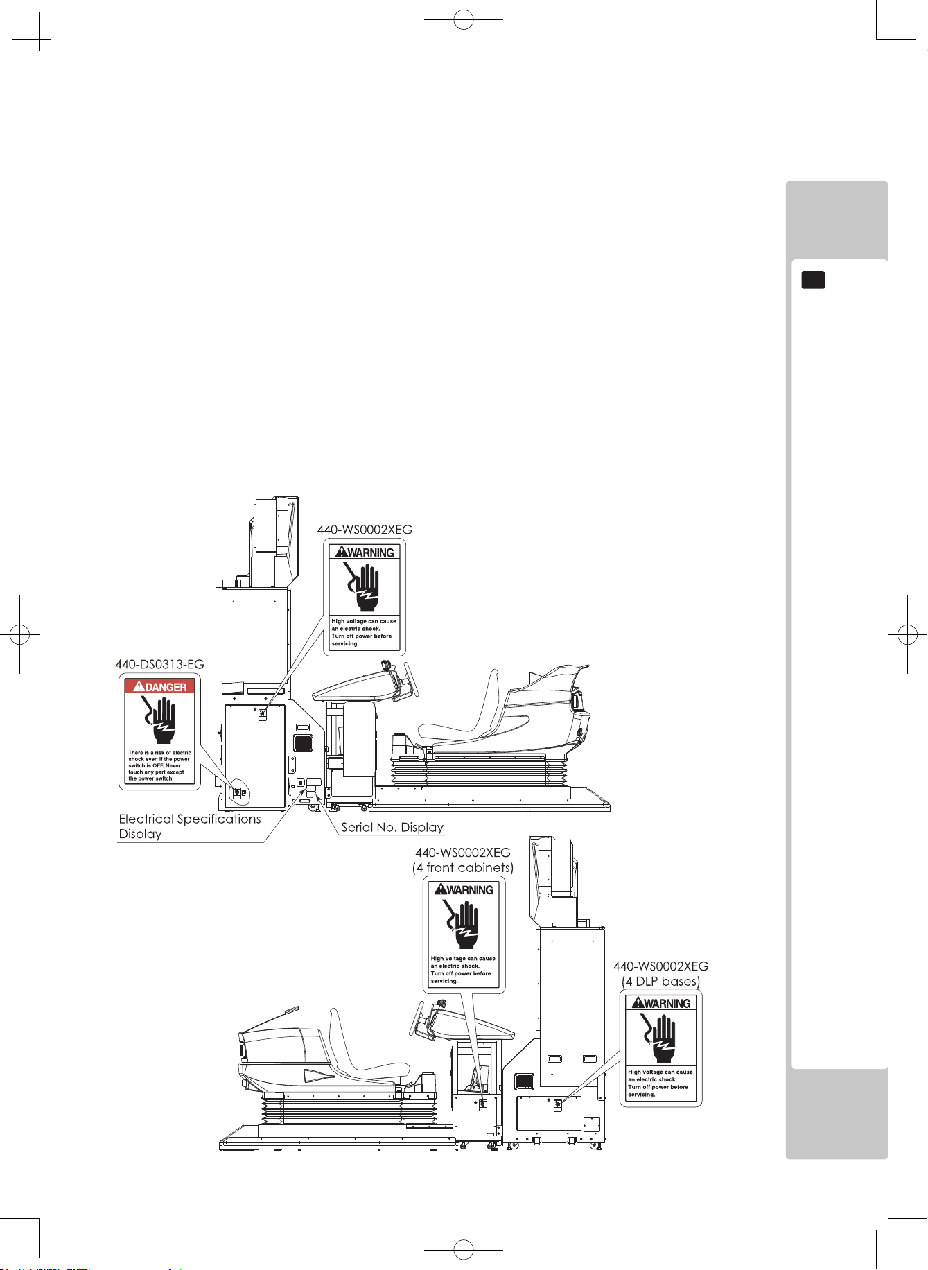
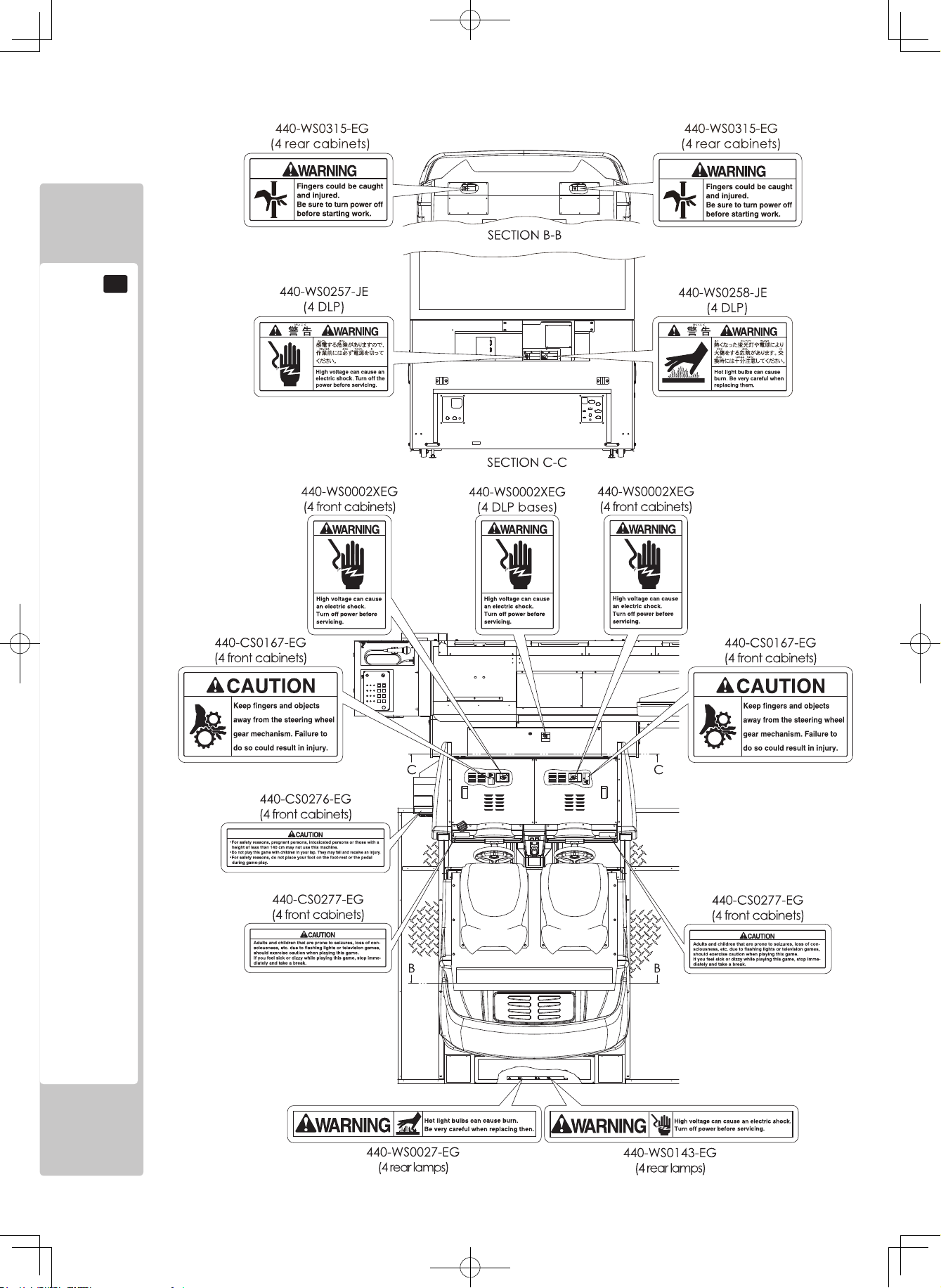
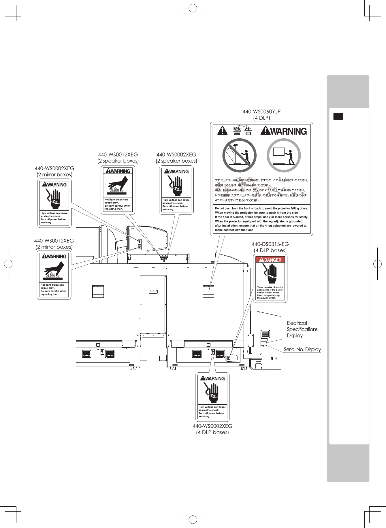
CONCERNING THE STICKER DISPLAY
This SEGA product has stickers attached describing
the product manufacture No. (Serial No.) and Electrical
Specifications. It also has a Sticker describing where to
contact for repair and for purchasing parts.
When inquiring about or asking for repairs, mention
the Serial No. and Name of Machine indicated on
the Sticker. The Serial Number indicates the product
register. Identical machines could have different
parts depending on the date of production. Also,
improvements and modifications might have been made
after the publication of this manual. In order to ensure
you order the correct parts, mention the Serial No. when
contacting the applicable places.
CONCERNING WARNING DISPLAYS
This SEGA product has warning displays on stickers,
labels and/or printed instructions adhered/attached to or
incorporated in the places where a potentially hazardous
situation could arise. The warning displays are intended
for accident prevention for customers and for avoiding
hazardous situations relating to maintenance and
servicing work. Some portions of the cabinet contain
high voltage and may cause accidents if touched. When
performing maintenance, be very careful of the warning
displays. It is especially important that any complex
repair and replacement work not mentioned herein
should be performed by those technical personnel who
have knowledge of electricity and technical expertise.
In order to prevent accidents, caution any customer
ignoring the warnings to cease and desist immediately.
Page 9
4
HANDLING PRECAUTIONS
1
Page 10
HANDLING PRECAUTIONS
5
1
Page 11
6
PRECAUTIONS REGARDING INSTALLATION LOCATION
2
2 PRECAUTIONS REGARDING INSTALLATION LOCATION
This product is an indoor game machine. Do not install it outside. Even indoors,
avoid installing in places mentioned below so as not to cause a fire, electric
shock, injury and/or malfunction.
- Places subject to rain or water leakage, or places subject to high humidity in
the proximity of an indoor swimming pool and/or shower, etc.
- Places subject to direct sunlight, or places subject to high temperatures in the
proximity of heating units, etc.
- Places filled with inflammable gas or places in the vicinity of highly inflammable/
volatile chemicals or hazardous matter.
- Dusty places.
- Sloped surfaces.
- Places subject to any type of violent impact.
- Places in the vicinity of anti-disaster facilities such as fire exits and fire extinguishers.
- Areas where the temperature exceeds the applicable temperature (ambient
temperature) range of 5 to 30 degrees centigrade.
● Be sure to che ck t he E lectrical Specifi cations. Ensure tha t this product
is compatible wit h the location’s power supply, voltage and frequency
requirements. A plate describing Electrical Specifications is attached to the
product. Non-compliance with the Electrical Specifications can cause a fire
and electric shock.
● A dedicated breaker and grounding mechanism are necessary for the control
tower and each cabinet of this product. Failure to heed this warning can cause
a fire or electric shock.
● Use wires of the following capacity for the indoor power wiring. The use of wires
of different electrical specifications can cause a fire or electric shock.
Control tower: Single phase AC 200-240 V, 15 A min.
Per cabinet: Single phase AC 200-240 V, 15 A min.
● Be sure to use an independent power supply equipped with an earth leakage
breaker. Using a power supply without an earth leakage breaker can cause an
outbreak of fire if a power surge occurs.
● Putting many loads on one electrical outlet can cause generation of heat and a
fire resulting from overload.
● Use cable as rated below for the power cable. Use of a rated cable that does
not satisfy the prescribed rating can cause fire and electric shock.
Single phase AC 200-240 V, 15 A min.
Electricity Consumption:
[Billboard, Control tower]
MAX. 5.0 A (Single phase AC 200 V, 50/60 Hz Area)
MAX. 4.1 A (Single phase AC 220 V, 50 Hz Area)
MAX. 4.1 A (Single phase AC 220 V, 60 Hz Area)
MAX. 3.9 A (Single phase AC 240 V, 50 Hz Area)
[Per cabinet]
MAX. 4.5 A (Single phase AC 200 V, 50/60 Hz Area) MAX. 4.3 A (Single phase AC 220 V, 50 Hz Area)
MAX. 4.6 A (Single phase AC 220 V, 60 Hz Area)
MAX. 4.1 A (Single phase AC 240 V, 50 Hz Area)
2-1 LIMITATIONS OF USAGE
Page 12
PRECAUTIONS REGARDING INSTALLATION LOCATION
7
2
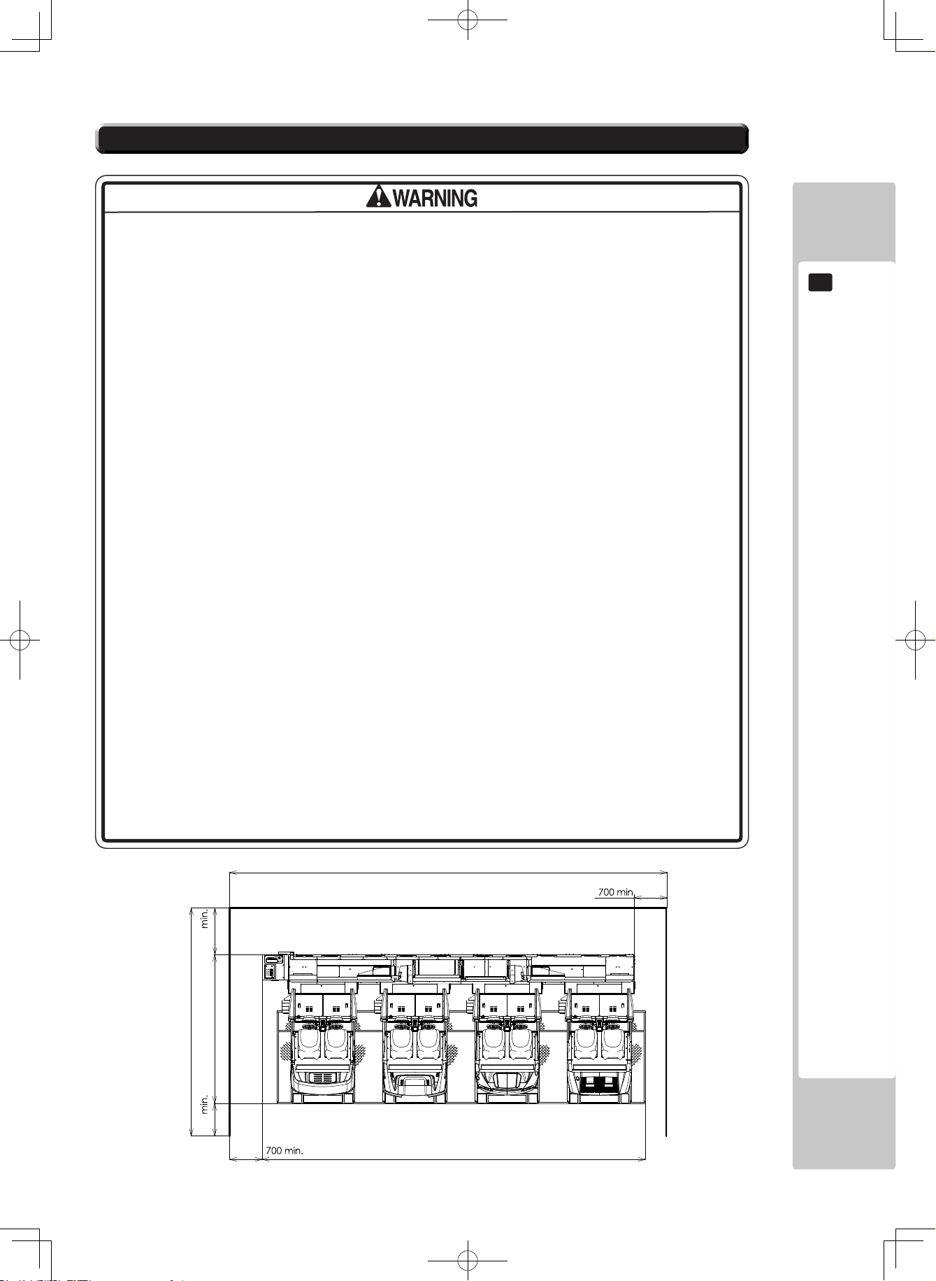
● For the operation of this machine, secure a minimum area of 9.4 m (W) x 4.9 m
(D). These dimensions are necessary to enable the customer to walk around the
machine and also to provide adequate ventilation. This machine is a ride, so
there is a possibility of a player falling off. In such an event, if a player strikes his
or her head, a serious accident may occur, so be sure to secure the minimum
area around the machine specified in this manual.
● Be sure to provide sufficient space specified in this manual. Do not allow objects
to block the ventilation ports. It can cause generation of heat and a fire.
● SEGA shall not be held responsible for damage or compensation for damage to
a third party, resulting from the failure to observe this instruction.
● If the machine does not fit through the entryway to the installation location, do
not disassemble it without first consulting the instructions. The machine should
only be disassembled in accordance with the instructions listed in this manual;
do not attempt to disassemble it in any other way. Specific tools and adjustment
procedures are required to assemble and disassemble the mechanical parts.
Attempting to assemble or disassemble the machine without consulting the
instructions may result in accidents during assembly/disassembly and electric
shock, short circuits, and/or personal injury during operation. If the machine still
does not fit through the entryway after following the procedures in this manual,
contact your retailer or the office listed in this manual.
● If the machine is still too large to fit through the entryway after following the
procedures listed in this manual, do not tip the machine on its side. Attempting
to transport the machine while it is tipped on its side may cause accidents. It
may also damage or warp parts of the machine, resulting in accidents during
operation.
● To install this product, the entrance must be at least 1.4 m in width and 1.45 m in
height. If the entrance is too narrow, do not tilt the product carelessly. If all the
product weight is put on the casters at one side only, there could be damage
or deformation, causing serious accidents such as workers getting caught
underneath.
● Secure a space of at least 0.7 m at the front of the control tower. Unless there
is sufficient space to allow the attendant to move freely in front of the control
tower, it will be impossible to guarantee safety in the event of an abnormality.
FIG.2 Operation area (Unit: mm)
(9400)
0001
8250
00
7
)0094(
0023
2-2 OPERATION AREA
Page 13
8
PRECAUTIONS REGARDING PRODUCT OPERATION
3
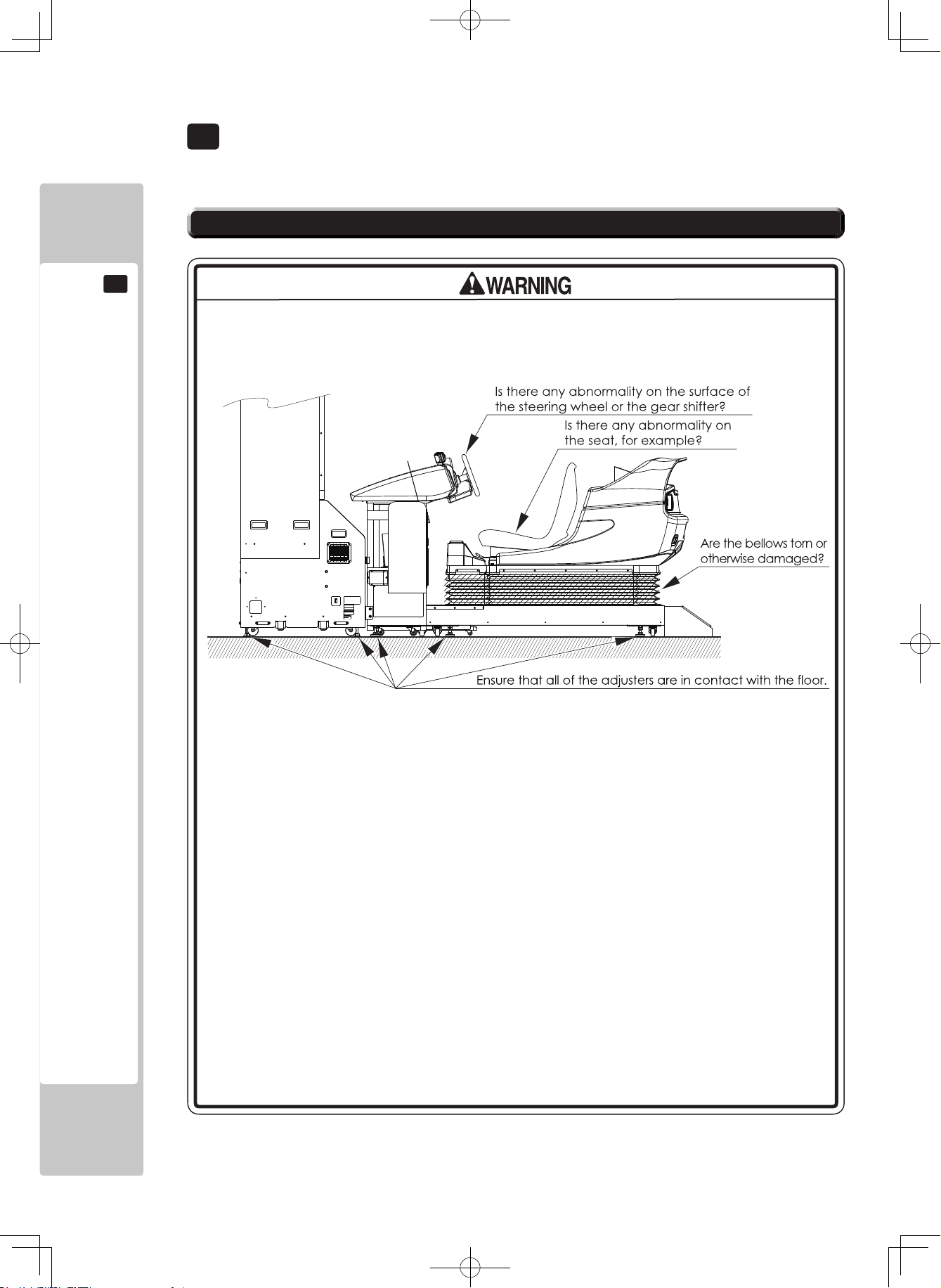
3 PRECAUTIONS REGARDING PRODUCT OPERATION
To avoid injury and trouble, be sure to pay attention to the behavior of visitors and players.
● Check if all of the adjusters are in contact with the surface. If they are not, the
cabinet can move and cause an accident.
● To ensure safety, carry out a trial run before starting operation, and be sure to check
the safety devices. Each ride moves, so each is equipped with safety devices. Be
sure to check that these safety devices function normally.
- Can you play a game when the motion of the ride has been stopped with the
motion selector switch on the control tower?
- When ride motion has been selected, can you stop the motion of the ride with
the motion selector switch on the control tower after the game has started?
- Does the ride stop when the MOTION STOP button at the center of the control
panel is pressed?
● Check each safety device and also check to see if any of the rides move
abnormally. Abnormal motion may cause an accident, so do not operate the
machine until the cause of the abnormality has been removed.
- Does the ride move in the direction corresponding to the direction of operation?
- Does the ride move smoothly?
- Is there any undesirable looseness in the ride?
- Is any unusual noise emitted while the ride is operating?
- Is any unusual vibration emitted while the ride is operating?
- Does the ride stop at an even position when the game is over?
3-1 BEFORE OPERATION
Page 14
PRECAUTIONS REGARDING PRODUCT OPERATION
9
3
● If an abnormality occurs in the ride mechanism, immediately stop operation, turn off
the power, and contact the office indicated in this manual or the point of purchase.
If you continue to operate the machine while there is an abnormality in it, a serious
accident such as an electric shock, short circuit, fire, or a fall may occur.
● The motion of the ride will not stop when the ride is touched by anybody other than
a player. Be sure to monitor the machine during a game.
● If a part related to the actuator of the ride mechanism breaks or deforms, for
example, necessitating replacement or repair of the part, request the office
indicated in this manual or the point of purchase to carry out this work. Specialized
knowledge, technical expertise, and tools are necessary for carrying out this work. If
you attempt to carry out this work yourself, an accident may occur.
● Be sure to perform appropriate adjustment of the projector. For operation of this
machine, do not leave monitor’s flickering or deviation as is. Failure to observe this
can have a bad influence upon the players’ or the customers’ physical conditions.
● It is suggested to prepare a rest space for players who feel sick after playing the
game.
● Do not put any heavy item on this product. Placing any heavy item on the product
can cause an accident fall or parts damage.
● Do not climb on the product. Climbing on the product can cause an accident fall.
To check the top portion of the product, use a step ladder.
● To avoid electric shock, check to see if door & cover parts are damaged or omitted.
● To avoid electric shock, short circuit and/or parts damage, do not put the following
items on or in the periphery of the product.
Flower vases, flowerpots, cups, water tanks, cosmetics, and receptacles/containers/
vessels containing chemicals and water.
● Inspect for the following items during a trial run. If there is any type of error, use the
Test Mode, etc., to resolve the problem. If you continue use with an error, it can
cause an accident or irreparable parts damage.
- Do the steering wheel and the ride move smoothly during the initialization
operation? (See Chapter 7.)
- Is there any strangeness in the operability of the steering wheels or the pedals?
- Is there any abnormality in the steering wheel reaction mechanism?
- Is there any improper adjustment of the projector screen?
- Are the bellows torn or has a screw dropped out of them?
● During daily cleaning, be sure to check the surface of the steering wheel, gear
shifter, and other parts that the player touches with his hands for damage, cracks,
or loose screws. If a player uses the machine while it is damaged, cracked, or has a
loose screw, the player may become injured.
● During daily cleaning, be sure to check the seat for any abnormality, wetness,
etc. Failure to do this may result in deliberate tampering or negligence being left
undetected.
Page 15
10
PRECAUTIONS REGARDING PRODUCT OPERATION
3
● Players directly hold the controller with their bare hands so it is recommended
that wet towels (paper towels) be provided.
● Endeavor to clean the steering wheel and seat frequently.
● Provide a container or space for storing the customers’ hand luggage, etc. To
help prevent an accident and also protect parts, establish measures so that
customers do not bring raingear, such as umbrellas, on rainy days, or juice or
other beverages, into the area where the machine is installed.
● During network play, if communication is interrupted for some reason, each
game will continue independently. Also, if communication is interrupted while in
Customer Welcome Mode, the Test Screen will appear.
● When one cabinet connected for network play enters the Test Mode, the other
cabinets will move to the Test Screen. For this reason, do not needlessly put a
cabinet in the Test Mode while a customer is playing a game, even if the cabinet
is not being used.
● You can make game settings and coin/credit (fee) settings individually, even
for cabinets that are connected for network play. You can also change the
settings of an individual cabinet to those for advanced players or beginners, for
example. Normally, however, set all of the cabinets to the same settings. If you
make a mistake in the fee setting, it is likely that the balance of payments and
other items will be adversely affected.
In order to prevent an accident or unnecessary trouble, the attendant or operator must endeavor to always pay
attention to the behavior of the players and customer. This machine has movable rides of about the same size as an
automobile. Sometimes a player or a customer may behave in an unexpected way. Be adequately aware of safety,
and stop any behavior that is considered dangerous.
● For safety, do not allow any of the following people to play the game.
- Those who have high blood pressure or a heart problem.
- Those who have experienced muscle convulsion or loss of consciousness
when playing video games, etc.
- Those who have neck or spinal cord problems.
- Those who are intoxicated or under the influence of drugs.
- Pregnant women or those who could be pregnant.
- Those who are not in good health.
- Those who do not follow the attendant’s instructions.
- Those who cannot grasp the Control Unit securely because of immobility in
fingers, hands or arms.
- Persons who disregard the product’s warning displays.
The game cannot be played while sitting in a wheelchair.
3-2 DURING OPERATION (PAYING ATTENTION TO CUSTOMERS)
Page 16
PRECAUTIONS REGARDING PRODUCT OPERATION
11
3
● For safety’s sake, a person of less than 140 cm in height cannot play games on
this machine. Because of the dimensions of the seat and the place where the
player puts his or her feet, there is a risk that when the ride moves the player
may fail to support their weight, causing the player to fall off the ride.
● Even players who have never been adversely affected by light stimulus might
experience dizziness or headache depending on their physical condition when
playing the game. Small children are especially likely to experience these
symptoms. Caution guardians of small children to keep watch on their children
during play.
● Instruct those who feel sick during play to have a medical examination.
● To avoid injury from falls and electric shocks due to spilled drinks, instruct the
player not to place heavy items or drinks on the product.
● To avoid electric shocks and short circuits, do not allow customers to put
hands and fingers or extraneous matter in the openings of the product or small
openings in or around the doors.
● For safety’s sake, warning indicators such as stickers are placed on the
machine. However, a careless player will generally fail to read these warnings.
The attendant must point out steps and level differences on the ride in order to
prevent the occurrence of an accident.
● To avoid falls and resulting injury, immediately stop customers from leaning
against or climbing on the product, etc.
● No more than 2 persons should sit on each ride of this machine. Instruct
customers that 3 or more players must not sit on a ride. Failure to observe
this precaution may result in players striking their bodies against each other,
causing them to receive blows, fall over, or fall off the ride.
● Instruct customers not to get on or in any ride part, such as the rear of the ride or
behind the back of the seat, other than the seat. Failure to observe this precaution
may results in players falling over, falling off, or catching body parts in the ride.
● Entering the cabinet with a wet umbrella or wet shoes is strictly forbidden. There
are electrical parts and wiring underneath the cabinet floor. If these become
wet, this can cause an electric shock or short circuit. Be especially careful in
managing the product on rainy days.
● Take care not to place a heavy object on a ride or seat. This may cause the
object to strike the player when the ride moves.
● Instruct customers not to play a game with a child on their knees. This may cause
an accident such as the child becoming caught between the control panel and the
player or the child falling off the ride.
● Instruct players not to stand during a game in which the ride moves. This may
result in the player falling off the ride or falling over.
● Instruct persons other than players to keep away from the machine while a game is
in progress. If a person touches the moving ride, this may result in an accident such
as the person falling over or getting his or her fingers caught in the bellows.
● An infant is unable to recognize danger, so instruct the guardian of the infant to be
attentive and ensure that the infant does not approach the machine.
Page 17
12
PRECAUTIONS REGARDING PRODUCT OPERATION
3
● Immediately stop such violent acts as hitting and kicking the product. Such
violent acts can cause parts damage or cause the cabinet to fall over, resulting
in injury.
● Items such as large finger rings can cause injury to the fingers while playing.
Instruct players to remove all accessories that could cause an accident before
playing.
● Take care to ensure that two persons do not attempt to play a game by
grasping a single steering wheel. Failure to heed this precaution may result in a
minor or a major collision.
● Explain that the MOTION STOP button can be pressed to stop play whenever the
player feels ill.
● Explain that the attendant will stop the game if he or she judges that a situation
is dangerous.
● Take care to ensure that other customers do not touch operating devices during
a game. Failure to heed this precaution may result in an accident or cause
trouble between customers.
● There are steps and level differences on each ride, so instruct players to be
careful when getting on or off the ride.
● Do not allow players to extend their hands or feet out from the ride during play.
Otherwise there could be bruises, sprains or other accidental injuries.
● Instruct the player to adjust the seat in the front-rear direction to match his or
her body size. If a player plays a game in an unreasonable posture, he or she
may sustain an injury or incur discomfort.
● The load limit on one ride of the machine is 300 kg. If you allow a person or
persons weighing more than the load limit to get on a ride and operate it, the
ride may break down or wear considerably.
● If a player carries hand luggage or other items onto a ride, objects may fall off or
roll over, for example, when the ride moves, resulting in injury or damage. Also,
instruct players not to take breakable items, etc., onto the ride.
● After the end of a game, check to ensure that the player has not forgotten or
dropped any belongings.
Page 18
PRECAUTIONS REGARDING PRODUCT OPERATION
13
3
3-3 PRECAUTIONS FOR TICKET OPERATION
When carrying out ticket operation, ensure that an attendant (operator) is present. Note, however, that it is assumed
that different operation methods are employed for each installation facility. Consequently, in this manual, common
precautions and handling procedures for operating this product are described. Individual precautions for operation are
the same as those set out in 3-1.
● To ensure safe operation, the attendant must pay attention to the behavior of the
players and also the performance of the ride and other machine parts. The points to
which the attendant must pay particular attention are as follows.
- Ensuring that the player watches his or her step when getting on or off the ride
- Paying attention to any belongings that the player takes onto the ride
- Checking the number of persons
- Explaining the precautions to be observed for preventing accidents
- Watching the players during a game
- Stopping the motion of the ride if an abnormality or accident occurs
- Prohibiting access by customers other than players
- Guiding the players off the ride at the end of the game
- Checking for forgotten or dropped items
- Checking the seat, steering wheel, gear shifter, etc.
- Guiding evacuation in the event of a fire or an earthquake
● To prevent the possibility of an accident, the following persons must play without
any ride motion. In order to prevent unnecessary trouble, explain this to the players
before the start of the game.
- Persons susceptible to motion sickness.
- Those who require supporting devices, etc., to walk.
- Those who cannot bend their knees because of illness, etc.
- Those who have fractures or other bone abnormalities anywhere in the body.
● Before leaving the control tower, the attendant must lock the cover of the service
panel. This is to prevent the possibility of a serious accident resulting from somebody
tampering with the controls.
● To operate the machine through ticket operation, unify the settings in the Test
Mode of the four cabinets by entering the GAME ASSIGNMENT MENU and
selecting TICKET1 (or TICKET2) for the OPERATION MODE.
● Set the main switch on the service panel of the control tower to ON. If it is not in
the ON position, the control tower cannot be operated.
● For the TICKET1 or TICKET2 setting, use a ticket, token, etc. A coin cannot be used.
Page 19
14
PRECAUTIONS REGARDING PRODUCT OPERATION
3
Control tower operation
The control tower has various switches and lamps, and a microphone. By controlling them, it is possible
to manipulate the CCD camera and each cabinet’s entry status, and also carry out a multi-cabinet start, PA
announcements, etc.
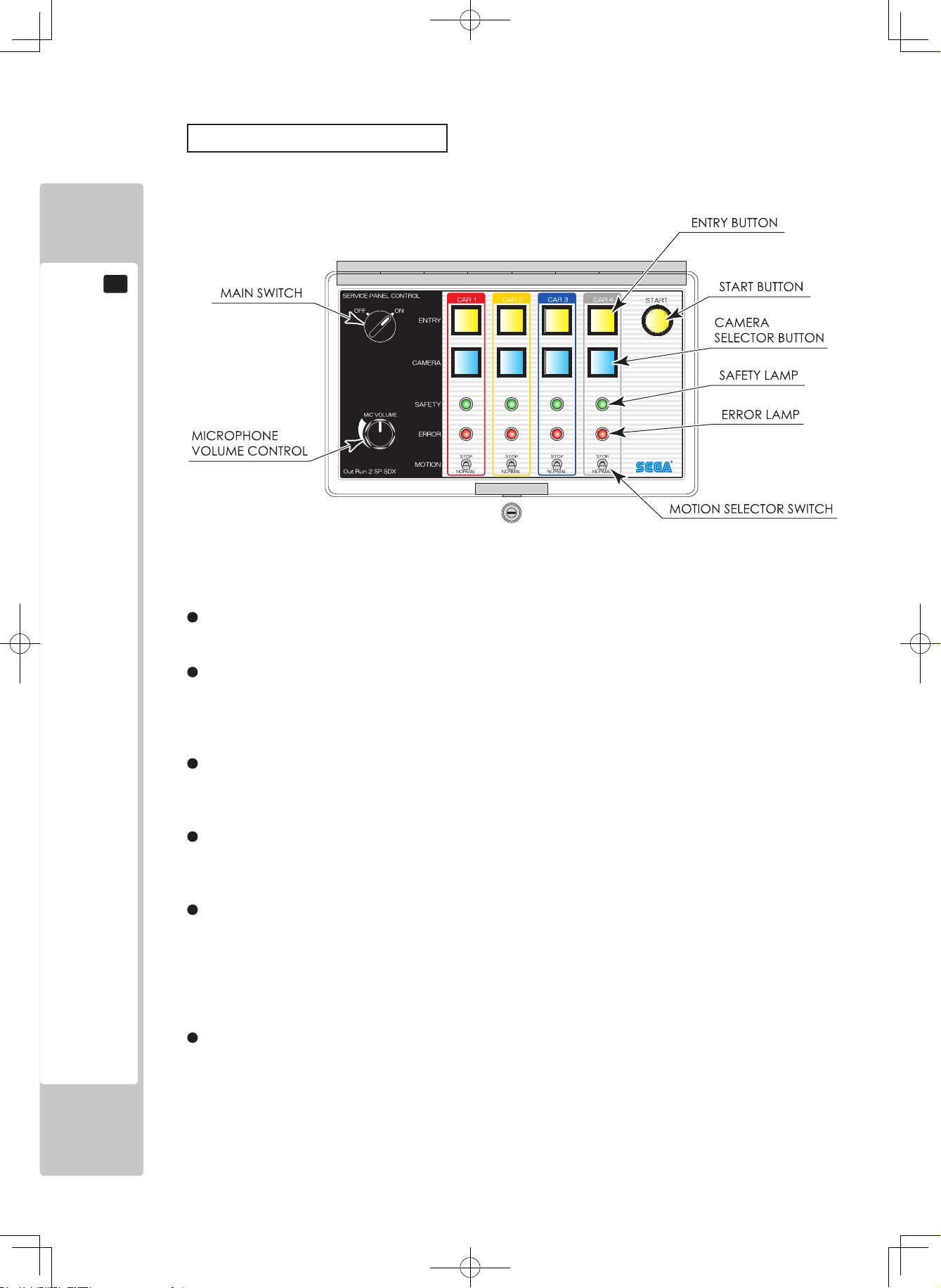
FIG. 3-2 Service panel
Main switch
This switch permits manipulation of the service panel. If it is not ON, the service panel cannot be manipulated.
ENTRY button
These buttons enable any desired cabinet (seat) to be entered into a game. When the button flashes, the
corresponding cabinet is in an entered status. It is possible to cancel the entered status by pressing the same
button once again.
START button
When this button is pressed, the status of cabinets entered into the game is finalized and the game starts.
While the game is in progress, ENTRY buttons remains lit until the game is over.
CAMERA selector button
These buttons enable any desired CCD camera image to be selected. The CCD camera image of the seat
corresponding to the button that is lit is displayed on the LCD screen on the billboard.
SAFETY lamp
While this lamp is lit, the motion operation of the ride is enabled. When the lamp is out, the ride is in a stopped
condition.
Lit: Motion takes place normally.
Out: The motion selector switch on the tower side is in the STOP position.
Flashing: The motion stop switch on the cockpit side has been pressed.
ERROR lamp
Flashes when an error occurs. The content of the error is indicated below.
Out: Communication takes place normally.
Flashing: There is abnormal communication between the tower control board and the actuator control board.
Page 20
PRECAUTIONS REGARDING PRODUCT OPERATION
15
3
MOTION selector switch
This switch selects either no motion (STOP) or motion (NORMAL) during a game. If this switch is in the STOP
position at the start of a game, motion will not take place until after the game is over.
It is also used to stop motion if NORMAL is selected and an abnormally occurs after the game starts.
MOTION STOP button at center of control panel
This button stops the motion of the ride during a game.
Immediately after the start of a race, an input can be made, and once this button is pressed the ride returns to its
initial position, and motion stops.
Unless the game is over, the motion stop condition cannot be canceled, and the ride cannot move.
Microphone volume control (MIC VOLUME)
Used to adjust the volume of the microphone that the attendant uses (for making announcements).
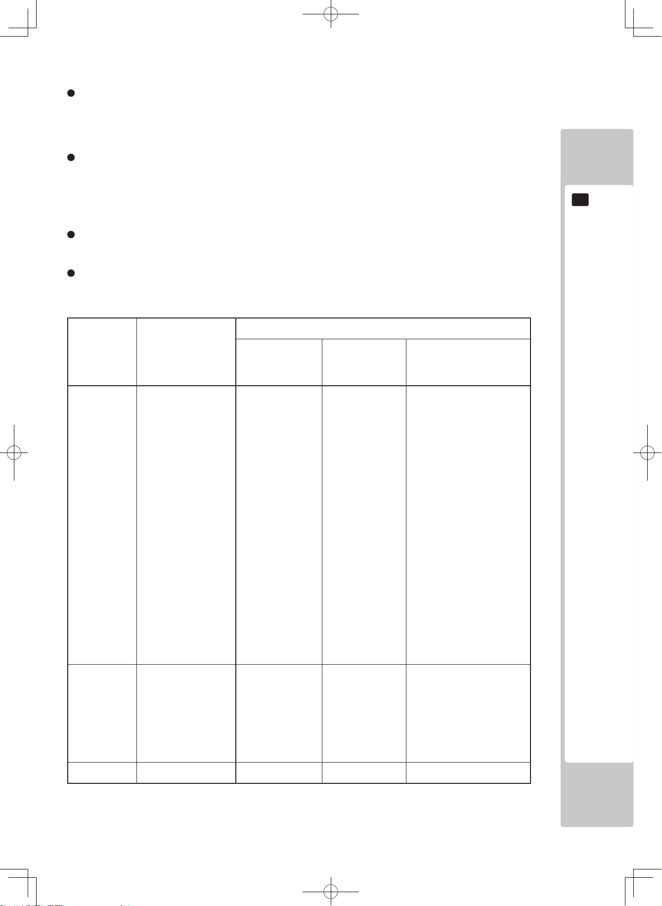
OPERATION MODE Settings
Attendant operation of the control tower is affected by each setting as shown below.
TABLE 3-2
OPERATION
MODE
Operation of
control tower
Work procedure
Operation 1
Entry method
Operation 2
Game start
method
Operation 3
Selection of
number of drivers
TICKET 1 Yes:
Entry and game start
operations can be
performed from the
control tower, and
any incorrect input,
which was made
when deciding the
number of drivers,
can be canceled, and
a selection made once
again.
Press the
ENTRY button
corresponding to
the cabinets that
you wish to enter
into a game.
Upon completion
of the entry,
press the START
button.
Once the players have
determined the number
of drivers, the screen
pauses temporarily, and
the machine waits for
input from the attendant.
Provided that there is no
problem with the selection,
the attendant should briefly
press the ENTRY button of
the desired cabinets. Then,
the next selection screen
appears.
If a mistake was made in
the selection of the number
of drivers, pressing the
ENTRY button of the
desired cabinets for an
extended period (at least
3 seconds) will cause the
previous screen to reappear.
TICKET 2 Yes:
Entry and game start
operations can be
performed from the
control tower.
Press the
ENTRY button
corresponding to
the cabinets that
you wish to enter
into a game.
Upon completion
of entry, press the
START button.
This completes
the work of the
attendant.
No
COIN No No No No
Page 21
16
PRECAUTIONS REGARDING PRODUCT OPERATION
3
If the power is turned off when the actuator that moves the ride is in an elongated condition, noise will be emitted
when the ride contracts.
Although there is no concern about wear or overloading, this occurrence is likely to cause apprehension. The
following is an explanation of how to turn the power off quietly by adhering to a certain set of steps.
Note, however, that this power off procedure cannot be conducted while a game is in progress.
1
Turn OFF the main switch on the service panel of the control tower. (See Fig. 3-2.)
2
When you wish to turn OFF the power switches of the four cabinets, press the START button on the service
panel for an extended period. Press the START button continuously for at least 3 seconds until the rides start
to move.
3
Each ride will move to its bottommost point and then stop.
4
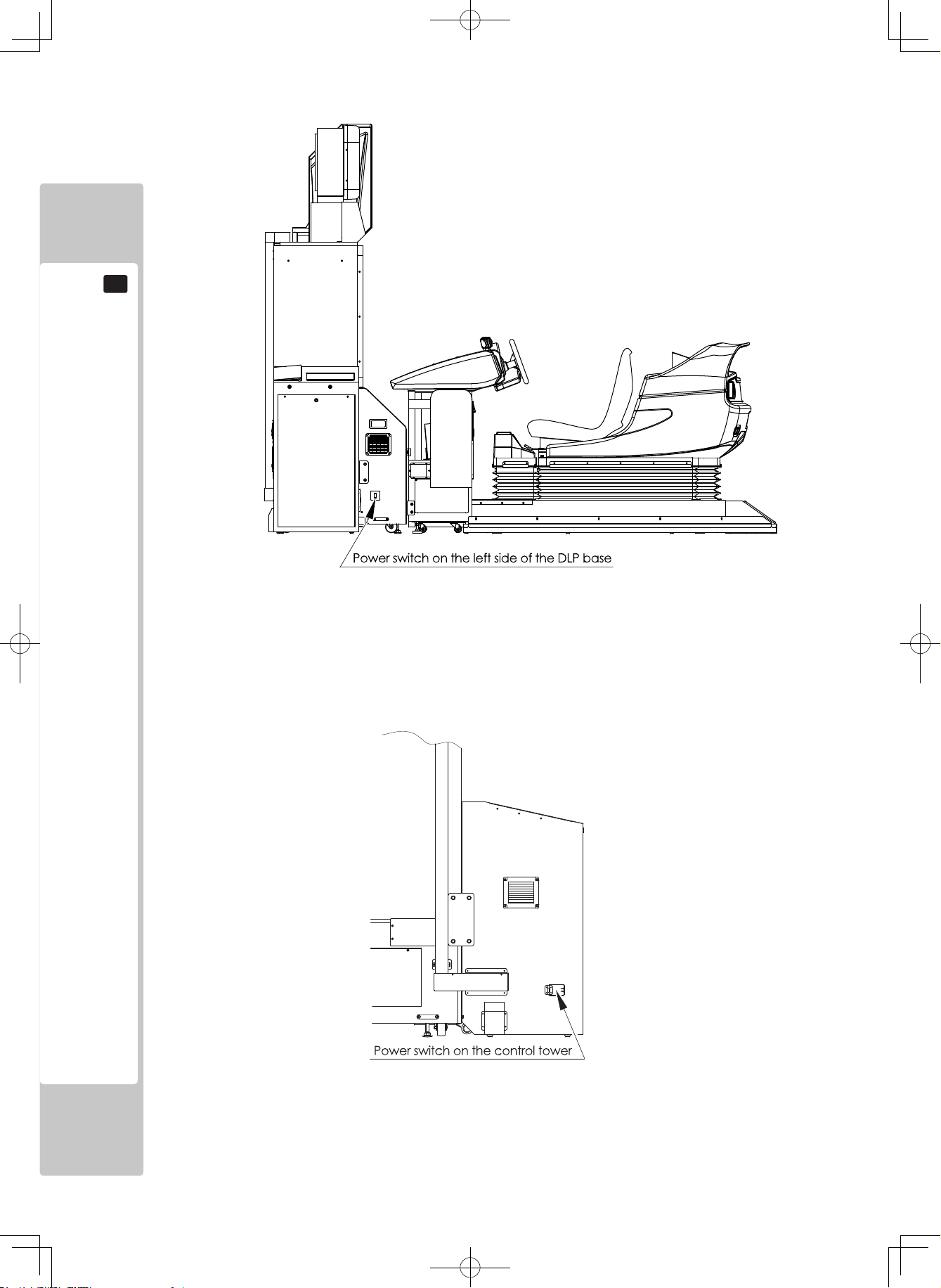
Turn OFF the power switch on the control tower. This switch is behind the lid on the left side seen facing
the control tower. (See Fig. 4c.)
If you turn OFF the power without carrying out the above procedure, the ride will descend a little at a time while
emitting a noise. This is the noise of the elongated actuator contracting.
Although the actuator will not wear due to this operation, you should carry out the above procedure before turning
OFF the power.
5
Before carrying out maintenance on a particular cabinet and cockpit, turn OFF the power switch on the side
of the DLP base of the target cabinet. (See Fig.4b.)
To turn OFF only the target cabinet, press the ENTRY button for the target cabinet on the service panel for an
extended period.
Press the button continuously for at least 3 seconds until the ride starts to move.
Only the ride of the target cabinet will move to its bottommost point and then stop.
3-4 SWITCHING OFF THE POWER
Page 22
PART DESCRIPTIONS
17
4
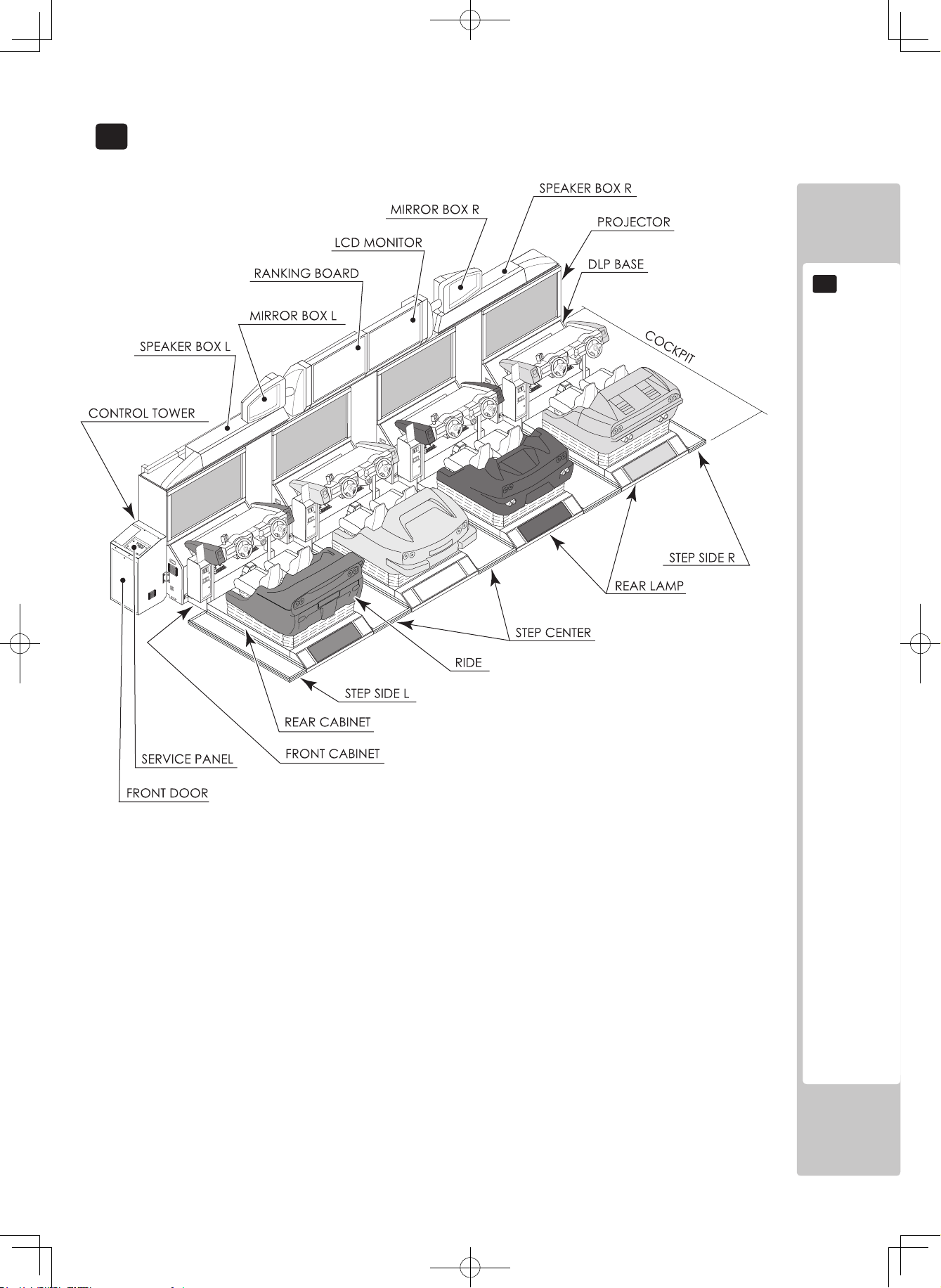
4 PART DESCRIPTIONS
FIG. 4a Overall Diagram
Page 23
18
PART DESCRIPTIONS
4
FIG. 4b
FIG. 4c
Page 24
PART DESCRIPTIONS
19
4
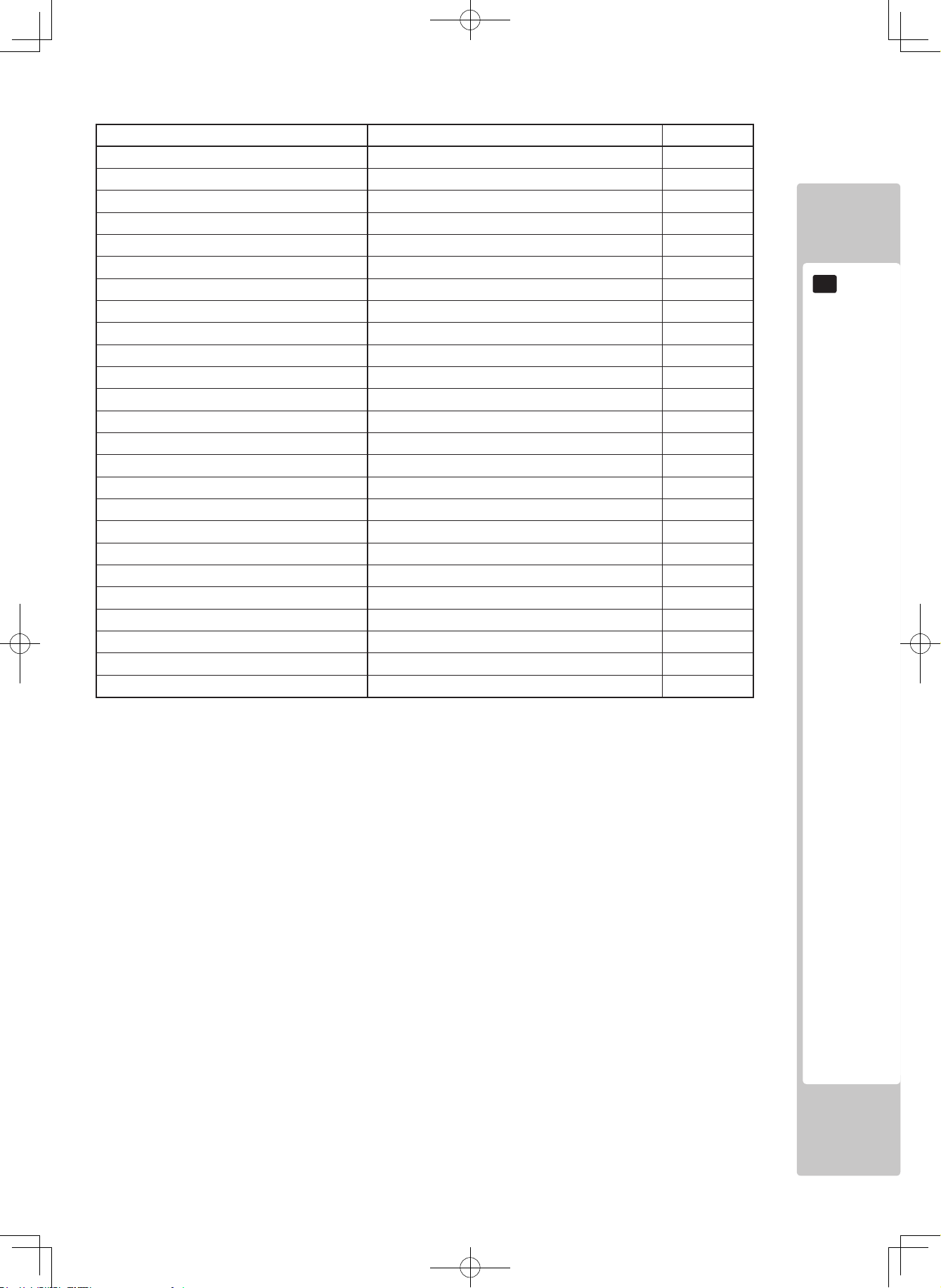
Name (quantity) Width × Depth ×
Height (mm)
Mass (kg)
REAR CABINET (4) W 1,400 × D 1,850 × H 1,170 363
FRONT CABINET (4)
W 1,620 × D 880 × H 1,250 177
DLP BASE (4) W 1,510 × D 850 × H 920 152
PROJECTOR (4)
W 1,510 × D 570 × H 1,400 110
REAR LAMP (4)
W 1,310 × D 360 × H 210 23
CENTER STEP (3) W 665 × D 1,990 × H 62 29
SIDE STEP L (1) W 332 × D 1,990 × H 62 18
SIDE STEP R (1)
W 332 × D 1,990 × H 62 18
CONTROL TOWER (1) W 565 × D 555 × H 1,065 87
RANKING BOARD (1) W 1,400 × D 620 × H 775 84
RANKING BASE W 1,400 × D 580 × H 115 -
RANKING BOX W 1,045 × D 180 × H 650 -
LCD UNIT (1)
W 1,400 × D 620 × H 775 68
LCD BASE W 1,400 × D 580 × H 115 -
LCD MONITOR
W 980 × D 95 × H 590 -
SPEAKER BOX L (1)
W 1,810 × D 580 × H 765 71
SPEAKER BASE L W 1,710 × D 580 × H 275 -
MIRROR BOX L W 935 × D 285 × H 500 -
SPEAKER BOX R (1) W 1,810 × D 580 × H 765 71
SPEAKER BASE R W 1,710 × D 580 × H 275 -
MIRROR BOX R W 935 × D 285 × H 500 -
Page 25
20
ACCESSORIES
5
5 ACCESSORIES
Confirm that the accessories listed in the table below are present when setting up the product.
Accessories marked “Spare” in the note column are consumable items but included as spares.
If there are an insufficient number of game play manuals, request the point of purchase or the office indicated in this
manual to supply additional manuals.
TABLE 5a
DESCRIPTION:
OWNER’S MANUAL
Part No. (Qty.):
420-6958-01 (1)
Note:
This manual
Figures:
Parts not labeled with part numbers are as yet
unregistered or cannot be registered. Be sure to handle
all parts with care, as some parts are not available for
purchase separately.
SERVICE MANUAL
420-6990-01 (1)
Explanation of software
PARTS CATALOG
420-6991-01 (1)
Parts list
LINDBERGH SERVICE MANUAL
420-6921-01 (1)
Explanation of built-in game board
KEY MASTER
220-5793-2-A001 (2)
For operating/closing the doors
The key master is shipped with the manual
packed together with the accessories.
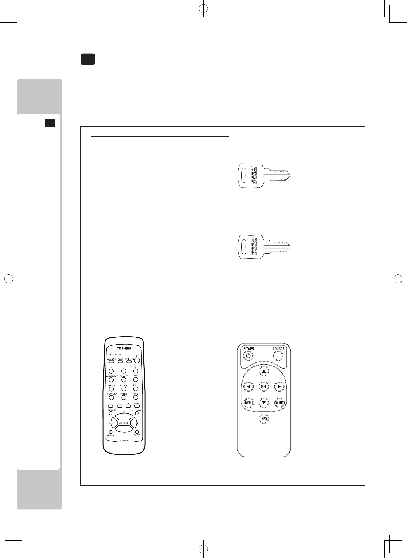
KEY
(2 each)
Each key is used for opening and closing the
coin chute door of a seat. The key for each seat
is different. The keys are placed inside the coin
chute doors for shipping.
PROJECTOR REMOTE CONTROLLER
200-6023 (4)
For making adjustments. (See Chapter 8.)
LCD REMOTE CONTROLLER
200-6060 (1)
For making adjustments. (See Chapter 9.)
Located inside the LCD packing box.
Page 26
ACCESSORIES
21
5
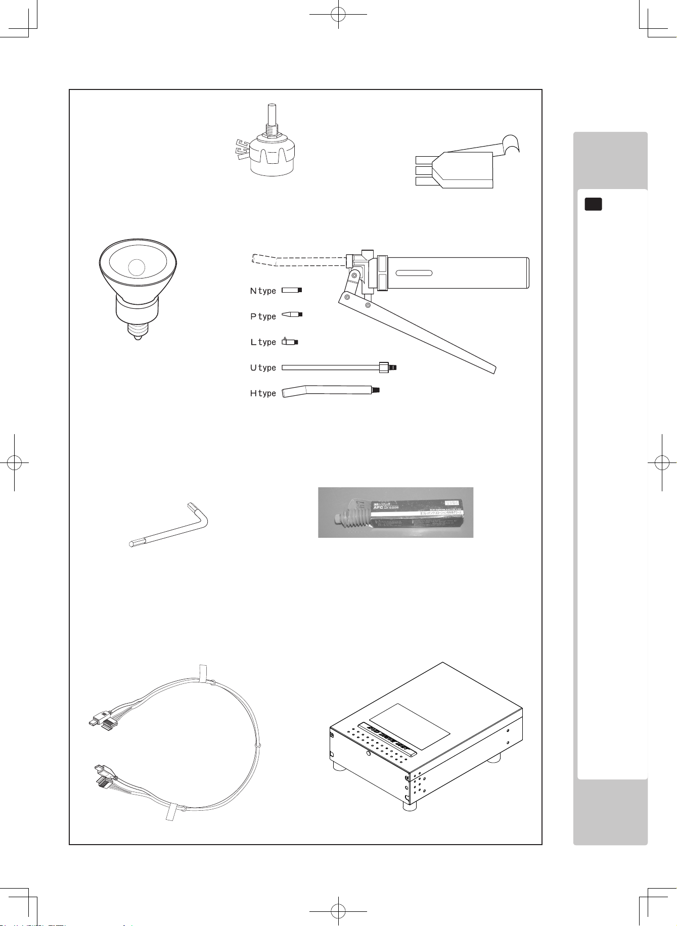
HALOGEN LAMP
390-6732-40M (5)
Spare. (See Chapter 15.)
Attached to the machine during
installation and assembly. An
additional 14 identical lamps
are packed together with the
machine.
GREASE GUN
090-0083 (1)
For greasing up. (See Chapter 14.)
GREASE
090-0289 (1)
For greasing up. (See Chapter 14.)
スポットランプ110V35W
390‑6730‑W(16)
アームに取付、
残り2個がスペア
6章、12章参照
TAMPERPROOF SCREW WRENCH
540-0007-01 (1)
Tool. (See Chapter 11.)
SERVICE MANUAL DVP ENG
420-6923-01 (1)
DVD DRIVE
610-0719-01-91 (1)
For software installation.
(See Chapter 18.)
ASSY WIRE DVD
605-0094 (1)
For software installation.
(See Chapter 18.)
VOLUME
220-5753/220-5484 (2)
Spare. (See Chapters 10 and 12.)
MICROSWITCH
509-5704 (2)
Spare. (See Chapter 11.)
Page 27
22
ACCESSORIES
5
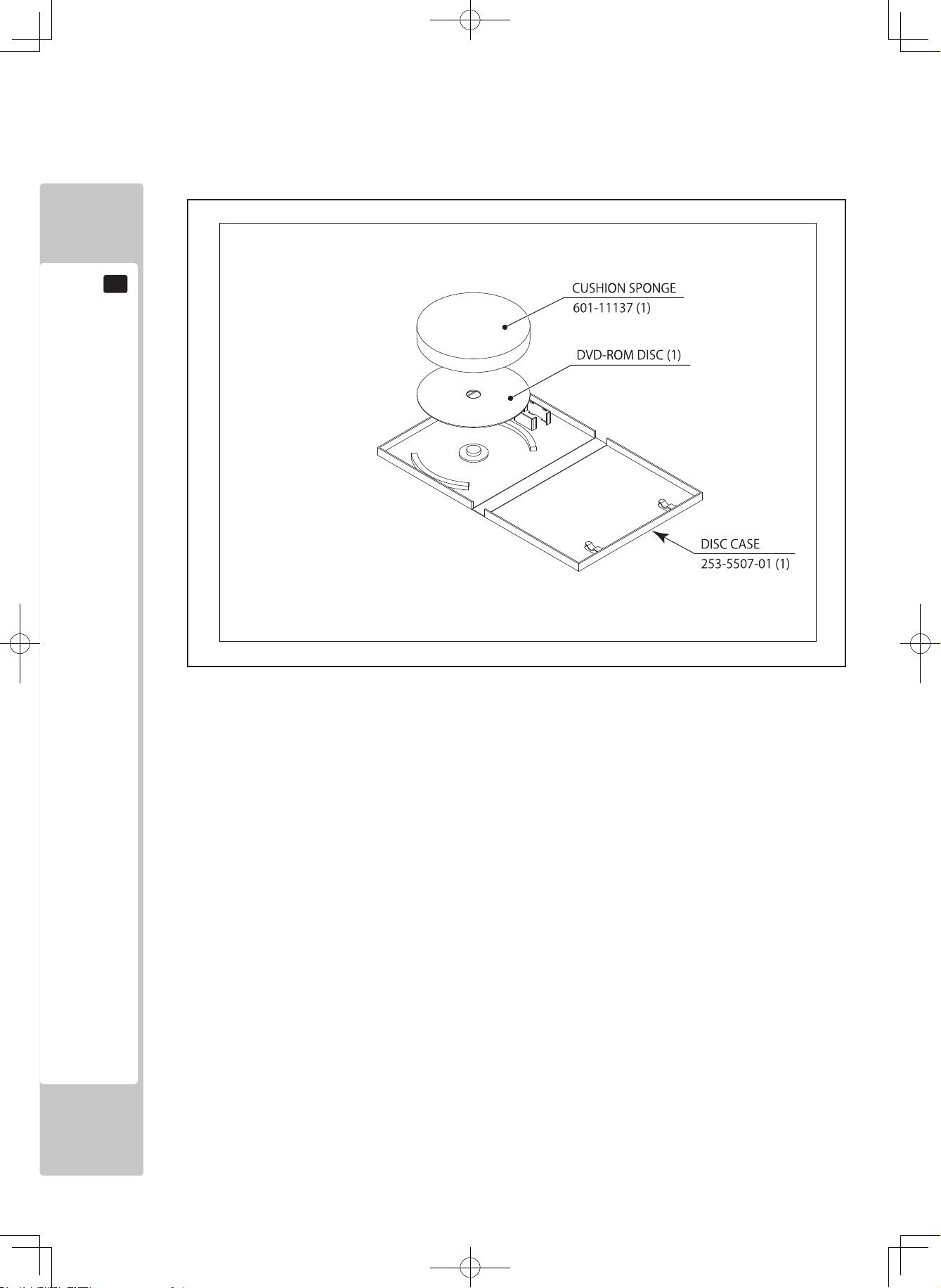
The parts shown in TABLE 5b are not used for normal maintenance. They are used to reinstall software that was
inadvertently uninstalled.
TABLE 5b
DVD SOFTWARE KIT
(1)
Software media.
(See Chapter 18.)
NOTE:
When you order the DVD-ROM disc only,
specify the part number 610-0726-0015 (DVD SOFT ORA).
Page 28
ACCESSORIES
23
5
● Perform assembly work by following the procedure herein stated. Failure to
comply with the instructions can cause electric shock.
● Perform assembling as per this manual. Since this is a complex machine,
incorrect assembling can cause an electric shock, machine damage and/or
improper functioning as per specified performance.
● When assembling, be sure to use plural persons. Depending on the assembly
work, there are some cases in which working by one person alone can cause
personal injury or parts damage.
● Adhere strictly to all of the work procedures stipulated in this document. If two
or more workers are working at the same time, exercise special caution. If
sequences are carried out erroneously, accidents can result. There might also
be cases in which the assembly cannot be completed.
● Pay special attention to the surroundings when a multiple number of workers
are working at the same time. There is always the danger that a worker might
be injured. In assembly and installation of this product, there are procedures in
which a stepladder is used, procedures in which heavy objects are attached,
and procedures involving connection of a rated power supply of 15 amperes.
Carelessness in doing work could lead to grave injuries and even fatalities.
● Ensure that connectors are accurately connected. Incomplete connections can
cause electric shock.
● This work should be carried out by the site maintenance personnel or other
qualified professionals. Work performed by non-technical personnel can cause
a severe accident such as electric shock. Failing to comply with this instruction
can cause a severe accident such as electric shock to the player during
operation. If no one with proper technological expertise is available, request
service from the office indicated in this document or the point of purchase so as
to ensure safety.
● Be careful not to damage the wires. Damaged wires may cause electric shock
or short circuit or present a risk of fire.
● Do not leave power cable or earth lines exposed over passageways. Exposure
could lead to damage, electric shock or short circuit. Wherever wiring has been
laid out on a floor surface, use a wiring protection cover. (Wiring diameter:
Power cable, approx. Ø18)
● Persons who connect indoor power supplies must be qualified electricians.
Do not allow anyone without proper qualifications to make such connections.
Otherwise there could be electric shock.
6 ASSEMBLY AND INSTALLATION
Page 29
24
ASSEMBLY AND INSTALLATION
6
● Provide power cables for connecting the indoor power supply to the product.
Four cables are needed for the cabinets, and one for the control tower. The
rating of each power cable must be at least 15 amperes. The cables must
conform to this requirement and also be of sufficient length to enable the indoor
power supply to be connected to the product without difficulty. Use of a cable
that does not meet the requirements can result in a fire or electric shock.
The recommended dimensions of the power cable terminal for cabinet use
are a hole diameter of 8.4 mm and width of 15 mm, and the recommended
dimensions of power cable terminal for control tower use are a hole diameter of
6.4 mm and width of 12 mm.
● Provide an earth wire for connecting the indoor earth terminal to the product
earth terminal. Unless grounding is secure, there could be electric shock,
damage to parts, or faulty operation.
The recommended dimensions of the terminal to be connected to the cabinet
earth terminal are a hole diameter of 8.4 mm and width of 15 mm, and those of
the control tower earth terminal are a hole diameter of 4.3 mm and width of 9.5
mm.
● For the sake of safety and workability, use 3 core coaxial cabtire cables for
the power cables. Note, however, that it is necessary to change the earth wire
terminal on the power cable for the control tower as indicated above.
● When inserting or removing a connector, always hold it by its main part. If you
hold it by anything else while doing so, the connections between wire and
connector terminal fixtures could be damaged; and there could be a short
circuit or fire.
● Make sure that all the adjusters are resting on the floor. The cabinet may move
and cause an accident if the adjusters are not laid out properly.
● Whene ver any fas teners (e.g. screws, nut s) have bee n lost, alw ays use
replacement fasteners with proper dimensions as specified in this document.
If fasteners of any other dimensions are used, it could cause damage and/or
separation of parts that result in secondary accidents.
● In order to perform the work of assembling this product reliably and safely,
provide a number of stepladders. If there is only one step ladder, it will be
difficult to carry out the work.
● Exercise due caution when using stepladders while working. If anyone stumbles
or falls, it could cause a serious accident. In locations where the ceiling is low, a
head injury could occur.
● Be careful when aligning, attaching or mounting parts so that your head, hands,
fingers, etc., do not get caught in anything. If two or more workers are working
at the same time, exercise special caution. Failure to be cautious could result
in accidental bone fractures or amputation. Check the surroundings carefully
before proceeding.
● When connecting wires inside the cabinet, there may be instances in which the
indoor lighting does not reach that location. Have a flashlight or other auxiliary
lighting equipment on hand. If wires are connected carelessly, there could be
an accidental short circuit, fire, etc.
Page 30
ASSEMBLY AND INSTALLATION
25
6
● After installing the step, be careful. If you trip over the step and fall over, you
may seriously injure yourself.
● When tightening bolts and screws, ensure that other parts are suspended
properly and bolts and screws are fastened tightly. Be sure to take accident
prevention measures such as having another worker support parts. If a part
drops or topples over during this work, a serious accident may result.
● When removing or attaching the door or parts, be careful that your hands or
fingers do not get caught in anything.
● Support and hold parts in place securely and fasten them with screws and/or
bolts. Use two workers, one to support the part and another to fasten it in place.
If a part is not supported securely, it might fall down, resulting in an accident.
● Wear appropriate work clothing so that work can be performed safely. Use
gloves and safety shoes to prevent accidents or injuries.
● When installing a wire protection cover over a floor, use a material shaped
so that no one passing by will stumble over it. Using a material that could be
stumbled over might lead to an accidental fall.
● Be careful in handling plastic parts. Be sure not to tighten screws or nuts
too tightly. If such parts are exposed to excessive loads or impact, they
might become damaged, resulting in fragments or cracks that could cause
accidental injury.
Page 31

26
ASSEMBLY AND INSTALLATION
6
1 Removing the shipping brackets
2 Assembling the projector and the DLP base
3 Joining the DLP projectors
4 Installing the DLP projector
5 Assembling the ranking board
6 Assembling the LCD monitor
7 Assembling the speaker box
8 Assembling the billboard
9 Assembling the cockpit
10 Joining the cockpit and DLP projector
11
Installing the cockpit
12 Attaching the step and rear lamp
13 Connecting the billboard wiring
14 Attaching the control tower
15 Connecting the power cable and earth
16 Attaching the play instructions stickers
17 Turning on the power
18 Checking assembly
This product consists of four cabinets, a billboard, and a control tower. The cabinet consists of a projector, DLP base,
cockpit (front cabinet and rear cabinet), and rear lamp assembled together.
Of the component parts of the cabinets, only the projectors are common to each other. The external body cover,
internal wiring, etc, are different.
The sequence in which the four cabinets are arranged is fastened. The sequence is 1P, 2P, 3P, and 4P seen facing the
projector screens when the cabinets are assembled. This sequence cannot be changed.
If you assemble the cabinets with the component parts set out incorrectly or with the cabinets in the wrong sequence,
the machine may fail to operate normally. Before assembly, carefully verify that all parts are to be set in the right
place.
The number sticker of each DLP base is on the rear of that DLP base.
● There are parts of similar shape, so carefully check the shape of each part.
● Confirm the direction of installation for a part before proceeding. Make sure you
understand the part’s orientation in terms of up or down, left or right, front or rear,
etc.
● Be careful in handling the projector screens. They can easily be damaged, and
if they are damaged, it might not be possible to service or repair them.
Page 32

ASSEMBLY AND INSTALLATION
27
6
The body color of each cabinet and the rear lamp nameplate are shown below.
1P: Red F50
2P: Yellow Dino246GTS
3P: Blue 360Spider
4P: Silver 512BB
FIG. 6a Component parts of cabinet
FIG. 6b No. indication on DLP base
Page 33

28
ASSEMBLY AND INSTALLATION
6
Tools necessary for work
- Philips screwdrivers (for M4, M5, and M8)
- Short Philips screwdriver or ratchet handle with Philips screwdriver tip (for M4)
- Socket wrenches or hexagon screwdrivers measuring distances of 10 mm, 13 mm, and 17 mm to opposite side (for
M6, M8, and M10 hexagon bolts and nuts)
- Spanner with measuring distance
of 24mm to opposite side
- Master key (accessory)
- Flashlight or other supplementary lighting
- Stepladder (height must be 1.5 meters min.)
24mm
Page 34

ASSEMBLY AND INSTALLATION
29
6
HEXAGON BOLT (4 ea.)
M6x16, w/spring washer,
flat washer used
1 REMOVING THE SHIPPING BRACKETS
Store the shipping brackets and fastening bolts carefully, because they are used to
prevent the product from becoming damaged while moving the product.
There are red-painted shipping brackets at the bellows at the rear part of the rear cabinets.
Remove the four hexagon bolts from each shipping bracket, and remove the shipping bracket. The bracket uses flat
washers with bolts that have spring washers attached.
FIG. 6-1a
FIG. 6-1b SHIPPING BRACKET
Page 35

30
ASSEMBLY AND INSTALLATION
6
2 ASSEMBLING THE PROJECTOR AND THE DLP BASE
● Be sure to have at least four persons lift the projector. Do not perform this work
using three or fewer persons. Failure to heed this warning may result in an
accident or injury to a worker.
● Be careful not to get your hands or fingers caught. Hold the projector by the
handles on the side, and also at the bottom part at the rear face. Failure to follow
this precaution may result in broken bones or amputation.
● In addition to the workers who carry the projector, have another worker support
the DLP base. This will prevent the base from moving and causing an accident.
● Once the projector has been mounted on the DLP base, promptly fasten it in
place. If it is left in an unfastened condition, an unforeseen accident may occur.
The screen of the projector is easily damaged, so try not to touch it during the
above work.
FIG. 6-2a
Mount the projector on the DLP base. Employ a total of at least five workers, four for carrying the projector, and one
for supporting the DLP base.
The DLP base has notches to enable the casters on the projector to pass into the DLP base. Mount the projector from
the side of the DLP base that has the notches.
1
Have at least four persons lift the projector, and place it on the DLP base.
Page 36

ASSEMBLY AND INSTALLATION
31
6
2
Align the projector and the DLP base so that their sides are in the same plane, and then push them together
so that there is no opening between them.
Be careful not to get your hands or fingers caught.
3
Remove the two fastening screws from the DLP front door.
4
Unlock the DLP front door using the master key, and then remove the door.
FIG. 6-2b
FIG. 6-2c
Page 37

32
ASSEMBLY AND INSTALLATION
6
5
Attach each of the two front holders (U-shaped rectangular sheet metal parts) with two hexagon bolts to the
inside of the DLP front door. The holders use flat washers with bolts that have spring washers attached.
When attaching the front holder, join the projector to the DLP base.
6
Attach joint A (L-shaped sheet metal part) to the rear corner of the projector. Fasten each joint A with four
hexagon bolts. Joint A use flat washers with bolts that have spring washers attached.
During this work, do not attach joint A on the left side of projector 1P. The same bolt holes are used to attach
the control tower. (See 14 .)
FIG. 6-2f JOINT A FIG. 6-2g
FIG. 6-2e
FIG. 6-2d FRONT HOLDER
Page 38

ASSEMBLY AND INSTALLATION
33
6
7
Attach two caster lids on the back of the DLP base, and fasten each of them with four screws. The screws
have flat washers and spring washers attached.
8
Connect the two wiring connectors inside the DLP base to the projector connectors. There are fastening
screws on both sides of the metal D-SUB connector. Secure the connectors with the screws after they are
connected.
9
Using a screw, fasten the round terminal at the tip of the earth wire already connected inside the DLP base.
Be sure to use a flat washer and spring washer with the screw.
10
Fasten the wiring of the connected connector using the cord clamp inside the DLP base.
11
Attach the DLP front door, lock it and fasten it with the two truss screws.
FIG. 6-2h CASTER LID FIG. 6-2i
FIG. 6-2j
Page 39

34
ASSEMBLY AND INSTALLATION
6
3 JOINING THE DLP PROJECTORS
Arrange the four DLP projectors consisting of the projectors mounted on their DLP bases alongside each other, and
join them together. Attach the following parts between the four projectors.
The parts to be attached between the four projectors are uniform. Note, however, that the wiring connections differ
according to the particular projectors.
JOINT UPPER (Total 3)
JOINT MIDDLE (Total 3)
JOINT HOLDER (Total 12)
JOINT LOWER (Total 3)
LAN JOINT (Total 10)
JOINT LOWER COVER (Total 3)
Page 40

ASSEMBLY AND INSTALLATION
35
6
DLP SIDE PLATE (Total 3)
JOINT WIRE COVER (Total 6)
Page 41

36
ASSEMBLY AND INSTALLATION
6
FIG. 6-3bFIG. 6-3a
3
Move the DLP projector so that the side of the DLP base and the side of the joint lower are firmly
connected.
Take care not to catch your hands or fingers.
Do not fasten the joint lower with the bolts at this stage. If you insert the bolts of the joint lower before
attaching the other parts, it will be difficult to then attach the other parts.
4
Temporarily fasten the two joint holders to the side of the projector using two hexagon bolts for each. The
joint holders use flat washers with bolts that have spring washers attached.
The mounting face is the side that faces the adjacent DLP projector. Do not attach joint holders on the left
side of 1P or the right side of 4P.
FIG. 6-3dFIG. 6-3c
1
Place the four DLP projectors alongside each other. The sequence is 1P, 2P, 3P, and 4P going from the left
seen facing the projector screens.
Check the sequence by observing the number stickers at the back of the DLP bases. (See FIG. 6b.)
2
Insert the rectangular pipe of the joint lower into the rectangular holes at the bottom of the side of the DLP
base. The side rectangular holes for the joint lower are towards the back of the DLP base (rear of screen).
Assemble the joint lower so that the rectangular holes in the DLP base still have remaining space (in the
shape of a rectangular hole) above the joint lower.
Attach a lid over the rectangular holes in the right side of the 4P DLP base.
Page 42

ASSEMBLY AND INSTALLATION
37
6
Inser t t he joint upper in to the op ening
between the joint holder and the projector
side. Fasten a hexagon bolt loosely so the
opening is kept intact.
5
Attach the joint upper in such a way that the sheet metal on the side of the joint upper is inserted into the
opening of the upper joint holder. The face that has a notch for passing the temporarily fastened bolts of the
joint holder is the side of the joint upper.
Also, the face with the rectangular holes is the screen side.
Do not tighten the temporarily fastened bolts at this stage.
FIG. 6-3e
RECTANGULAR HOLE
JOINT UPPER
FIG. 6-3f FIG. 6-3g
Page 43

38
ASSEMBLY AND INSTALLATION
6
6
Attach the joint middle in such a way that the sheet metal on the side of the joint middle is inserted into the
opening of the lower joint holder. The face that has a notch for passing the temporarily fastened bolts of the
joint holder is the side of the joint middle. Also, the face with the rectangular holes is the screen side.
Do not tighten the temporarily fastened bolts at this stage.
7
Fasten the joint lower to the DLP base. Tighten three hexagon bolts on one side of each side. The joint lower
uses flat washers with bolts that have spring washers attached.
FIG. 6-3h
FIG. 6-3i
Page 44

ASSEMBLY AND INSTALLATION
39
6
8
Tighten all of the temporarily fastened bolts of the joint holder.
9
Attach the DLP side plate (wooden board). Attach the upper and lower sheet metal parts so that they are
suspended from the rectangular holes in the joint upper and joint middle. Hoist the central sheet metal part
and attach it.
FIG. 6-3j FIG. 6-3k
FIG. 6-3l FIG. 6-3m
Page 45

40
ASSEMBLY AND INSTALLATION
6
10
Fasten the DLP side plate using six hexagon bolts. Use three bolts each for the joint upper and middle,
respectively. The joint upper and middle use flat washers with bolts that have spring washers attached.
11
Remove the 2 screws fastening the DLP back door at the back of the DLP base. The screws have spring
washers and flat washers attached.
FIG. 6-3n FIG. 6-3o
FIG. 6-3p
Page 46

ASSEMBLY AND INSTALLATION
41
6
12
Unlock the DLP back door with the master
key, and remove the door. Remove the doors of
all four DLP bases.
13
Connect the wiring between the DLP bases. Withdraw the wiring from the side rectangular hole, and
connect the connector to it inside the joint lower.
The wires and LAN cables have tags on them. Connect wires and LAN cables that have the same tags. Also,
use LAN joints to connect the LAN cables.
FIG. 6-3q
FIG. 6-3r FIG. 6-3s
FIG. 6-3t
Page 47

42
ASSEMBLY AND INSTALLATION
6
14
There is an earth wire in the wiring on the
left side facing the back of the DLP base. At
the bottom of the joint lower there is a screw
hole the vicinity of which is left unpainted.
There is a screw temporarily fastening the
earth wire. Remove the earth wire fastening
screw, and then fasten the round terminal of
the earth wire. Be sure to use a spring washer
and a flat washer with the screw.
15
Attach the joint lower cover on the joint
lower. Take care not to damage the wiring.
16
Fasten the joint lower cover using two screws.
Each screw has a flat washer and spring
washer attached.
FIG. 6-3u
FIG. 6-3v
FIG. 6-3w
Page 48

ASSEMBLY AND INSTALLATION
43
6
17
Attach the joint wire cover by the left and right rectangular holes of the joint lower cover, and fasten each
with seven screws. The screws have a flat washer and spring washer attached. Be careful not to damage the
wiring.
FIG. 6-3x
Page 49

44
ASSEMBLY AND INSTALLATION
6
4 INSTALLING THE DLP PROJECTOR
● Carefully check the surrounding area while moving the projector. If you get
caught between the product and the wall, a serious accident may occur.
● Be sure to ground the adjusters, and secure the product firmly to the installation
location. If the projector moves either during assembly work or during operation
after the completion of assembly, a serious accident may occur.
● Secure adequate space at the back of the product to enable workers to pass
by the product without problem. A confined space may result in an accident
during work. It will also prevent work from being carried out accurately and
reliably.
● When the adjusters are grounded and secured to the installation location, the
projector cannot be moved easily. Carefully check the distance between
nearby walls and other installed items when grounding the adjusters.
● If the floor where the projector is to be moved is made of carpet or decorative
sheeting, there is a risk of wear or staining.
Grasp the handles at the side of the projector or the side of the DLP base, or hold
at the bottom, and then either push or pull to move and change direction. Do not
push or hold the sheet metal part because this may result in injury.
Each DLP base has four casters and four adjusters. (See FIG. 6-4d.) Move to the installation position, directly ground
the adjusters, provide an opening of about 5 mm between the floor surface and the casters, and perform adjustments
so the machine is level to the ground.
The subsequent assembly work includes placing a ladder at the back of the product and the connecting of power
cables.
Be sure to secure enough space at the back of the product to enable workers to pass by the product easily.
Page 50

ASSEMBLY AND INSTALLATION
45
6
1
Move the four joined DLP projectors to the installation position. Grasp the handles at the side of the
projector or the side of the DLP base, or hold at the bottom, and then either push or pull to move and change
direction.
2
After moving the DLP projectors to the installation position, check the passageway for customers to ensure
that it has a width of at least 1.2 m, and that there is a clearance of at least 1 m behind the product. Attach
the control tower to the left side of the 1P DLP projector.
Secure at least 1.5 m at both sides.
FIG. 6-4a
FIG. 6-4b
Page 51

46
ASSEMBLY AND INSTALLATION
6
3
Ground all of the adjusters at the bottom of
the DLP base.
4
Adjust the height of the adjusters. Provide a clearance of about 5 mm between the casters and the floor
surface. After adjustment, tighten the nuts of the adjusters in the upward direction so as to secure the height.
FIG. 6-4c Ground adjusters
FIG. 6-4e Adjustment of adjusters
FIG. 6-4d Bottom view of four DLP bases joined together
Page 52

ASSEMBLY AND INSTALLATION
47
6
5 ASSEMBLING THE RANKING BOARD
Assemble the ranking board to be attached over the 2P DLP projector.
1
When the product is shipped, the ranking box and the front cover have already been assembled. Remove
four truss screws, and remove the front cover.
2
Remove two screws, and remove the billboard electric cover from the ranking base.
FIG. 6-5b FIG. 6-5c
FIG. 6-5a
Page 53

48
ASSEMBLY AND INSTALLATION
6
3
Have the ranking box lifted up by two persons, and then placed on the ranking base. Take care not to catch
the wiring.
4
Fasten the ranking box by its bottommost frame to the ranking base with a total of eight screws.
When fastening the screws, use either a short screwdriver or a ratchet handle with screwdriver tip. Each
screw has a flat washer and spring washer attached.
FIG. 6-5d FIG. 6-5e
FIG. 6-5f
FIG. 6-5g
Page 54

ASSEMBLY AND INSTALLATION
49
6
5
Attach the two base frames upper at the left and right of the back of the ranking box. Fasten each base frame
using four screws. Each screw has a flat washer and spring washer attached.
6
Connect the wire connector of the ranking
box to the board and connector panel inside
the billboard electric.
7
Return the billboard electric cover to its
initial position, and fasten it with two screws.
Take care not to damage the wiring.
FIG. 6-5h
FIG. 6-5i
FIG. 6-5j
Page 55

50
ASSEMBLY AND INSTALLATION
6
8
Attach the front cover.
Attach the front cover from the bottom so that the tab at the bottom of the ranking box hitches with the
bottom of the front cover. After hitching the tab, attach the front cover so as to cover the top part.
9
Fasten the front cover using four truss
screws.
FIG. 6-5k
FIG. 6-5l
FIG. 6-5m
FIG. 6-5n
Page 56

ASSEMBLY AND INSTALLATION
51
6
10
Attach the upper joint to side wood L. Fasten it with two screws. Each screw has a flat washer and spring
washer attached.
11
Attach side wood L.
Insert side wood L into the side of the ranking box, and fasten it to the ranking box and the ranking base
with five screws. Each screw has a flat washer and spring washer attached.
FIG. 6-5p FIG. 6-5q
FIG. 6-5o
Page 57

52
ASSEMBLY AND INSTALLATION
6
6 ASSEMBLING THE LCD MONITOR
Have at least two persons carry the LCD monitor. If the LCD monitor is carried by
only one person, it may drop or topple over, resulting in bodily harm. Also, the
worker is likely to injure his or her shoulder or back.
Assemble the LCD monitor to be attached over the 3P DLP projector. Attach the LCD monitor to the LCD base.
FIG. 6-6a LCD MONITOR
1
Before the product is shipped, the LCD frame and LCD holder are already assembled. Remove the four
hexagon bolts, and remove the LCD holder from the LCD frame. The LCD frame and LCD holder use flat
washers with bolts that have spring washers attached.
FIG. 6-6b
Page 58

ASSEMBLY AND INSTALLATION
53
6
2
Place the LCD frame on the LCD base, and fix it with four hexagon bolts. The LCD frame and LCD base
use flat washers with bolts that have spring washers attached.
3
Remove the four screws already fastened on the back of the LCD monitor. These screws are used to attach
the following parts. They have flat washers and spring washers attached.
Have one person support the LCD monitor, and another worker remove the screws.
FIG. 6-6c
LCD BASE LCD FRAME
FIG. 6-6d
Page 59

54
ASSEMBLY AND INSTALLATION
6
4
Atta c h the LC D ho l der ov er th e LCD
monitor, and fix it with two screws. Use the
two screws that you removed from the back
of the LCD monitor in the upper side screw
holes at the back of the LCD monitor.
5
Place the LCD monitor on the LCD frame, and hitch the LCD holder to the LCD frame. Be sure to have at
least two persons perform this work.
6
Fix the LCD holder with the LCD frame
with four hexagon bolts. The LCD holder
and the LCD frame use flat washers with
bolts that have spring washers attached.
FIG. 6-6e
FIG. 6-6f
FIG. 6-6g
Page 60

ASSEMBLY AND INSTALLATION
55
6
7
Fix the bottom of the LCD monitor to the LCD frame with two screws. Use the two screws that you
removed from the back of the LCD monitor in the lower side screw holes at the back of the LCD monitor.
8
Attach the LCD front cover to the front of the LCD monitor. Hitch the left and right rectangular holes at the
bottom of the LCD front cover, and then attach the cover so that it covers the LCD holder.
9
Fix the LCD front cover to the LCD frame
with three truss screws.
FIG. 6-6h
LCD FRONT COVER
FIG. 6-6i
FIG. 6-6j
Page 61

56
ASSEMBLY AND INSTALLATION
6
10
Fix the upper joint LCD to the LCD frame with two screws. The screws have flat washers and spring
washers attached.
11
Attach the upper joint to the side wood R. Fix the joint with two screws. The screws have flat washers and
spring washers attached.
UPPER JOINT LCD FIG. 6-6k
FIG. 6-6l
Page 62

ASSEMBLY AND INSTALLATION
57
6
12
Attach side wood R, and fix it with a total of five screws. The screws have flat washers and spring washers
attached.
13
Align the wire cover base with the depression at the center of the back of the LCD monitor, attach it, and
then fix it to the LCD frame with two screws. The screws have flat washers and spring washers attached.
FIG. 6-6m
WIRE COVER BASE FIG. 6-6n
Page 63

58
ASSEMBLY AND INSTALLATION
6
14
Connect the wiring to the LCD monitor. Connect the AC cable, which is included in the accessories of the
LCD monitor, to the connector at the back of the LCD monitor and also the outlet over the base.
Bundle the connected AC cable using the band that was used to pack it.
Of the accessories packed with the LCD monitor, the only ones used are the AC cable and the remote
controller.
15
Connect the video signal connector wired to the LCD base to the connector at the back of the LCD monitor.
AC CABLE FIG. 6-6o
FIG. 6-6p
Page 64

ASSEMBLY AND INSTALLATION
59
6
16
Fix the earth wire round terminal to the LCD frame using one screw. Be sure to fit a spring washer and a flat
washer over this screw.
17
Install the wire cover upper, and fix it with the two screws. The screws have flat washers and spring washers
attached. Be careful not to damage the wiring.
WIRE COVER UPPER FIG. 6-6r
FIG. 6-6q
Page 65

60
ASSEMBLY AND INSTALLATION
6
18
Fix the wire cover lower using four screws. The screws have flat washers and spring washers attached. Be
careful not to damage the wiring.
WIRE COVER LOWER FIG. 6-6s
Page 66

ASSEMBLY AND INSTALLATION
61
6
7 ASSEMBLING THE SPEAKER BOX
Assemble the speaker box to be attached over the DLP projector of 1P and 4P. Attach the mirror box to the speaker
box base.
The 1P side uses speaker box L, and the 4P side uses speaker box R. The parts on the L side and R side are different,
but the assembly method is the same. The following description applies to the assembly of the R side. Assemble the
L side using the same procedure.
1
Open the two halogen doors on the back of
the speaker box base R. Unfasten two screws
for each. The screws have flat washers and
spring washers attached.
2
Pull out the wiring inside the door through
the rubber grommet.
FIG. 6-7a SPEAKER BOX BASE R FIG. 6-7b SPEAKER BOX R
FIG. 6-7c
FIG. 6-7d
Page 67

62
ASSEMBLY AND INSTALLATION
6
3
Remove the fastening screw of the back door at the back
of the mirror box. The screw has a flat washer and a spring
washer attached.
Remove the back door, pulling it straight up.
4
Place the mirror box on the grommet, from which the wiring was pulled out, over the speaker box base.
Make sure that the speaker side of the speaker box base and the half-mirror side of the mirror box are facing
in the same direction. Be careful not to damage the wiring pulled from the grommet.
Tilt the mirror box. Pass the wiring brought out from the grommet into the inside of the mirror box through
the opening resulting from tilting of the mirror box.
FIG. 6-7e
FIG. 6-7f FIG. 6-7g
Page 68

ASSEMBLY AND INSTALLATION
63
6
5
Secure the mirror box with five screws.
The screws have flat washers and spring
washers attached.
6
Connect the two connectors on the ends of the wires passed to the inside of the mirror box, to the two
connectors inside the mirror box.
7
In order to prevent an accident during the work of placing the speaker box on the DLP projector, secure the
opened halogen door and the removed back door.
FIG. 6-7h
FIG. 6-7i
Page 69

64
ASSEMBLY AND INSTALLATION
6
8 ASSEMBLING THE BILLBOARD (ILLUMINATION UNIT)
Carry out this work using the number of persons and the tools specified in this
manual. If you work with fewer than the number of specified persons or without the
required tools, an accident may occur. Be sure to employ at least four persons to
lift the ranking board, LCD monitor, and speaker boxes L and R, and ensure that
they cooperate with a person standing on a step ladder and providing assistance.
● Take care not to get your hands or fingers caught when placing the various
parts on the DLP projector or when adjusting the positions of the parts.
● Place the ranking board, LCD monitor, and speaker box from the side of the
DLP projector. If you attempt to place these parts from the front, irreparable
damage, such as damage to the projector screen, may occur.
1
Attach the eight base hooks and the two side base hooks at the back of the top plate of the four DLP
projectors arranged alongside each other, and fix each of them with two hexagon bolts. The hooks use flat
washers with bolts that have spring washers attached.
Attach the side base hooks on both ends. The bolt holes used for attaching the base hooks differ according
to the base attachment position.
FIG. 6-8a
Page 70

ASSEMBLY AND INSTALLATION
65
6
FIG. 6-8b (Unit: mm)
(255)(530)(190)
3P4P
(175)
(530)(255)
(315)
1P
2P
(290)(175)
(190)
2
Place the ranking board on the DLP projectors from the 1P side. Employ five persons to do this work. Have
one of these persons stand in readiness at the top of a step ladder placed at the back of the DLP projector.
If the work space is confined, install the ranking board on the projector from the projector screen side,
taking care not to strike it against the screen.
FIG. 6-8c
Page 71

66
ASSEMBLY AND INSTALLATION
6
3
Move the ranking board to the fixing position. Align the right edge of the ranking board with the centerline
of the four DLP projectors. Take care not to catch your hands or fingers.
4
Secure the ranking board with three hexagon bolts. The ranking board uses flat washers with bolts that have
spring washers attached.
5
Place the LCD monitor on the DLP projectors from the 4P side. This work requires five persons. Have one
of these persons stand in readiness at the top of a step ladder placed at the back of the DLP projector.
If the work space is confined, install the LCD monitor from the projector screen side, taking care not to
strike it against the screen.
FIG. 6-8eFIG. 6-8d
FIG. 6-8f
Page 72

ASSEMBLY AND INSTALLATION
67
6
6
Move the LCD monitor to the fixing position. Align the left edge of the LCD monitor with the centerline of
the four DLP projectors. Take care not to catch your hands or fingers.
7
Secure the LCD monitor with five hexagon bolts. The LCD monitor uses flat washers with bolts that have
spring washers attached.
8
Attach the center vacuum units to the side wood R of the LCD monitor and also to the side wood L of the
ranking board, and secure each of them with four truss screws.
HEXAGON BOLT (5), black
M6x40, w/spring washer, flat washer used
FIG. 6-8g FIG. 6-8h
FIG. 6-8l
FIG. 6-8i CENTER VACUUM L FIG. 6-8j CENTER VACUUM R
FIG. 6-8k
Page 73

68
ASSEMBLY AND INSTALLATION
6
9
Place speaker boxes L and R on the DLP projectors. Place L on the left side of the ranking board, and R on
the right side of the LCD monitor. Employ five persons to do this work. Have one of these persons stand in
readiness at the top of a step ladder placed at the back of the DLP projector.
If the work space is confined, place the speaker boxes from the projector screen side, taking care not to
strike it against the screen.
10
Move the speaker box to the fixing position. Move until the protruding part of the mirror box touches the
billboard side cover. Be careful not to catch your hands or fingers.
11
Fix the speaker box with five hexagon bolts. The speaker box uses flat washers with bolts that have spring
washers attached.
FIG. 6-8n
FIG. 6-8o
FIG. 6-8m
Page 74

ASSEMBLY AND INSTALLATION
69
6
12
Place the L and R billboard side covers on
the DLP projector. Place L on the 1P side
and R on the 4P side.
Be sure to fix them securely to the ends of
each speaker box base.
13
Fasten the L and R billboard side covers using three hexagon bolts. The L and R billboard side uses flat
washers with bolts that have spring washers attached.
FIG. 6-8q
FIG. 6-8r
FIG. 6-8p
Page 75

70
ASSEMBLY AND INSTALLATION
6
14
Open the two halogen doors at the back of
the L and R speaker boxes. Unfasten two
screws for each. The screws have flat washers
and spring washers attached.
15
Five lamp sockets are located on the inside of
the open halogen doors. Attach the halogen
lamps into the sockets. Be sure to not touch
the surface of the glass at the front of the
lamps. It is possible that they will burn out if
oils from fingers are present.
16
Remove the back door fastening screw at the back of the
mirror box. The screw has flat and spring washers attached.
FIG. 6-8s
FIG. 6-8t
FIG. 6-8u
Page 76

ASSEMBLY AND INSTALLATION
71
6
17
Remove the back door by sliding it directly upwards.
18
Attach halogen lamps to each of the two lamp sockets on the
inside of the back door. Be sure not to touch the surface of
the glass at the front of the lamps. It is possible that they will
burn out if oils from fingers are present.
19
Close all of the open halogen doors and fasten each with two screws. Reattach all of the back doors and
fasten each with one screw.
FIG. 6-8v FIG. 6-8w
FIG. 6-8x
Page 77

72
ASSEMBLY AND INSTALLATION
6
9 ASSEMBLING THE COCKPIT
Assemble the four cabinets’ cockpits. Join the front cabinets and rear cabinets together, and connect the wiring. Be
sure that the color of the front cabinet parts matches the body color of the rear cabinet.
FIG. 6-9a Match the color of the front cabinet and rear cabinet
1
Remove the left and right floor sections of the
rear cabinet. Remove three truss screws for
each. The left and right floors are identical.
2
Join t he fro nt cabine t and rea r cabin et
together by inserting the two rectangular
pipes of the front cabinet into the U-shaped
rectangular hole on the underside of the rear
cabinet. Be careful not to get your hands or
fingers caught.
FLOOR
TRUSS SCREW (3 ea.), black
M5x12
FIG. 6-9b
FIG. 6-9c
Page 78

ASSEMBLY AND INSTALLATION
73
6
3
Fasten the front cabinet and rear cabinet
to gethe r w ith ei ght hexagon bol ts. Use
four bolts inside each of the left and right
floors. Check to ensure that all eight bolts
can be tightened properly before tightening
them fully. These bolts use flat and spring
washers.
4
Remove the two truss screws fastening the
motor driver door on the right side of the
front cabinet.
5
Unlock using the master key, and remove the motor driver door.
FIG. 6-9d
FIG. 6-9e
FIG. 6-9f
Page 79

74
ASSEMBLY AND INSTALLATION
6
6
Pass the rear cabinet wiring into the interior of the front cabinet, and connect the two connectors.
7
Inside the left side floor, pull the front cabinet wiring to the rear cabinet, and connect the connector.
8
Pass the m ot or dr iver wiring (the black
covered wiring with the L and R tags) and
the earth wire to the front cabinet.
FIG. 6-9g FIG.6-9h
FIG. 6-9i FIG. 6-9j
FIG. 6-9k
Page 80

ASSEMBLY AND INSTALLATION
75
6
9
Pull the motor driver wiring and the earth wire through to the front of the front cabinet. Connect the earth
wire to the earth terminal.
10
The two parts with the white casing at the front of the front cabinet is the motor driver. Connect the wiring
connector with the L tag to the near side of the motor driver, and the wiring connector with the R tag to the
far side of the motor driver.
11
Reattach the left and right floors to their
original positions, and fasten three truss
screws for each.
FIG. 6-9l
FIG. 6-9m FIG. 6-9n
FIG. 6-9o
Page 81

76
ASSEMBLY AND INSTALLATION
6
10 JOINING THE COCKPIT AND DLP PROJECTOR
Join each DLP projector and cockpit. The order of the cockpits is already determined. 1P is the red body, 2P is
yellow, 3P is blue, and 4P is silver.
1
Place the four cockpits in front of the DLP projectors. The sequence of body color is red, yellow, blue, and
silver going from the left seen facing the projector screens.
2
Fully attach the two temporarily fastened L-shaped joint brackets at the front left and right of the cockpit.
Remove the two hexagon bolts from each of the temporarily fastened joint brackets facing the corners. The
joint brackets use flat washers with bolts that have spring washers attached.
FIG. 6-10b
FIG. 6-10a
Page 82

ASSEMBLY AND INSTALLATION
77
6
3
Attach the joint brackets so that they extend
out to the left a nd right , re spec t ive l y.
Tempo r aril y faste n ea c h wi t h th e two
hexagon bolts that were removed.
4
Place the cockpit near the DLP projector. As the wiring is
not long, keep the distance between them at around 10 cm.
The connector panels are to the front left and right of the
DLP projector. Besides the connector panel connectors,
there is an earth wire inside the rectangular hole on the left
side. Inside the rectangular hole on the right side, there is a
wire for the yellow connector.
FIG. 6-10c
FIG. 6-10e LEFT SIDE CONNECTOR PANEL
FIG. 6-10f RIGHT SIDE CONNECTOR PANEL
FIG. 6-10d
Page 83

78
ASSEMBLY AND INSTALLATION
6
5
Remove one screw from the near side motor
driver terminal. The screw uses flat and spring
washers. Be careful not to misplace these
washers.
6
Fasten the round terminal of the earth wire
pulled from the DLP projector to the motor
driver terminal with the removed screw. Make
sure to always use flat and spring washers with
the screw.
7
Connect the two cockpit wiring connectors
to the connector panel on the left side of the
DLP base.
FIG. 6-10g
FIG. 6-10h
FIG. 6-10i
Page 84

ASSEMBLY AND INSTALLATION
79
6
8
Pull out the wiring for the yellow connector
from the inside of the right side rectangular
hole. Connect with the yellow connector of
the cockpit side wiring.
9
Connect the eight cockpit wiring connectors
to the connector panel on the DLP base right
side.
10
Completely align the cockpit with the front side of the DLP projector. Be careful not to catch the wiring.
11
Pass two hexagon bolts into the DLP projector side bolt holes of each of the joint brackets. Ensure that all
four bolts can be fully tightened, before temporarily fastening them. The joint brackets use flat washers with
bolts that have spring washers attached.
FIG. 6-10j
FIG. 6-10k
FIG. 6-10l
Page 85

80
ASSEMBLY AND INSTALLATION
6
12
Attach the motor driver door, lock it, and secure with two truss screws.
FIG. 6-10m
Page 86

ASSEMBLY AND INSTALLATION
81
6
11 INSTALLING THE COCKPIT
● Carefully check the surrounding area while moving the product. If caught
between the product and a nearby wall, a serious injury could result.
● Always ground the adjusters, and secure the product to the installation site. If
this is not done, a serious accident may result as the product may move during
assembly work, or during operation after assembly is completed.
● Make sure that there is enough space behind the product for workers to pass
by. During work, an accident may result if this space is too narrow. Also, it may
become too difficult to perform the work accurately and reliably.
Each cockpit has eight casters and six adjusters. (See FIG. 6-11b.) Directly ground the adjusters, provide a clearance
of about 5 mm between the floor surface and the casters, and perform adjustments so the machine is level to the
ground.
1
Ground all the adjusters on the underside of
the cockpit.
2
Adjust the height of the adjusters. Provide a
clearance of about 5 mm between the casters
and the floor surface. After adjustment,
tight en the nuts o f t he adj ust ers in an
upward direction so as to secure the height.
FIG. 6-11a Ground adjusters
FIG. 6-11b
Page 87

82
ASSEMBLY AND INSTALLATION
6
FIG. 6-11c Adjust the adjusters
3
Fully tighten the four fastening bolts for each of the cockpit joint brackets temporarily fastened to the DLP
projector side.
Page 88

ASSEMBLY AND INSTALLATION
83
6
12 ATTACHING THE STEP AND REAR LAMP
There are three kinds of board parts for the step. There is a step center, which is attached between cockpits, a step
side L, which is attached on the left side, and a step side R, which is attached on the right side.
When attaching the step, the rear lamp is also attached at the same time to the cockpit base rear part. Each rear lamp
is different. Match each rear lamp with the correct cockpit body color before attaching.
The following metal board parts are used when attaching the step and rear lamp.
REAR LAMP (Total 4)
STEP HOLDER R (Total 4) STEP HOLDER L (Total 4)
STEP LID L, R (4 each)
STEP CENTER (Total 3)
STEP SIDE L, R
Page 89

84
ASSEMBLY AND INSTALLATION
6
1
Temporarily fasten the left and right step holders to the step center, step side L and R, with two hexagon
bolts for each. Use only a step holder R for the step side L, and a step holder L for the step side R. The step
holders use flat washers with bolts that have spring washers attached.
2
Insert the step center between the cockpits,
and fasten to each cockpit with two hexagon
bolts. At that time, fully tighten the temporarily
fastened step holder bolts.
The step holders and step center use flat
washers with bolts that have spring washers
attached.
FIG. 6-12a STEP CENTER
FIG. 6-12b STEP SIDE R
FIG. 6-12c
Page 90

ASSEMBLY AND INSTALLATION
85
6
3
Secure the step side L and R in the same
way. Both step side L and R use flat washers
with bolts that have spring washers attached.
4
Remove the rear lamp lids on both sides.
Remove two truss screws from each. The left
and right lids are identical parts.
5
Align a rear lamp with each cockpit rear
part. At that time, pull out the fluorescent
light wiring and the earth wire from the hole
in the left rear area of the cockpit, and draw
them into the inside of the rear lamp. Be
careful not to catch the wiring.
Pay attention to the nameplate design in the
center of the rear lamp. The photo below
showing “F50” is for the 1P rear lamp.
FIG. 6-12e
FIG. 6-12d
FIG. 6-12f
TRUSS SCREW (2 ea.), black
M4×8
Page 91

86
ASSEMBLY AND INSTALLATION
6
6
Secure the rear lamp with two hexagon bolts.
The bolt hole for fastening the rear lamp is
visible from the hole that appears after the
lids are removed. The rear lamp uses flat
washers with bolts that have spring washers
attached.
7
Connect the connector to the inside of the
lid on the rear lamp left side and connect the
earth wire to the rear lamp.
FIG. 6-12g
FIG. 6-12h
Page 92

ASSEMBLY AND INSTALLATION
87
6
FIG. 6-12i
8
Reattach the removed lids at their original
positions. Secure each with two truss screws.
9
Attach the step lid L and R. The slanted side is for the rear lamp side. Use nine truss screws for each step
lid. The truss screws use flat washers.
FIG. 6-12j
Page 93

88
ASSEMBLY AND INSTALLATION
6
Connection of the wiring between the billboard and all corresponding parts (LCD monitor, ranking board, speaker
box L and R, billboard side cover L) will be conducted.
Work will be conducted from above the DLP projector at a high elevation. Make sure to use a step ladder. An
accident may result if a worker attempts to climb up the projector or hang onto the projector, etc.
As well as connecting the wiring connectors, attach an earth plate between the connectors and the adjacent parts’
metal parts (duct). The earth plate enables grounding, so always be sure to attach it.
1
Connect the wiring found between the speaker
box R and the LCD monitor. Remove the
duct cover on the rear of the speaker box R.
Remove two screws. The screws have flat
and spring washers attached.
2
Remove the LCD monitor duct cover. Remove
two screws. The screws have flat and spring
washers attached.
13 CONNECTING THE BILLBOARD WIRING
FIG. 6-13a
FIG. 6-13b
The earth plate used for grounding has a painted face and an unpainted face.
Attach so that the unpainted face faces the metal parts. If grounding is not
achieved, an accident such as an electric shock or short circuit may occur.
Page 94

ASSEMBLY AND INSTALLATION
89
6
3
Remove the screw to connect the earth wire,
and connect the earth wire. The screw has flat
and spring washers attached.
4
Connect the two connectors. Then, return
the duct covers to their original positions
and secure them. Be careful not to catch the
wiring.
5
Connect the wiring found between the LCD
monitor and the ranking board. Remove the
duct cover on the rear of the LCD monitor.
Remove two screws. The screws have flat
and spring washers attached.
FIG. 6-13c
FIG. 6-13d
FIG. 6-13e
Page 95

90
ASSEMBLY AND INSTALLATION
6
6
Rem ove the r ank ing board duc t cove r.
Remove two screws. The screws have flat
and spring washers attached.
7
Remove the screw to connect the earth wire,
and connect the earth wire. The screw has
flat and spring washers attached.
8
Connect four connectors. Then, return the
duct covers to their original positions and
secure them. Be careful not to catch the
wiring.
FIG. 6-13f
FIG. 6-13g
FIG. 6-13h
Page 96

ASSEMBLY AND INSTALLATION
91
6
9
Remove the duct cover adjacent to the duct
cover that was removed from the back of
the ranking board. Remove two screws. The
screws have flat and spring washers attached.
10
Connect the wiring found between the ranking
board and the speaker box L. Remove the
duct cover on the rear of the ranking board.
Remove two screws. The screws have flat and
spring washers attached.
11
Remove the speaker box L duct cover. Remove
two screws. The screws have flat and spring
washers attached.
FIG. 6-13i
FIG. 6-13j
FIG. 6-13k
Page 97

92
ASSEMBLY AND INSTALLATION
6
12
Remove the screw to connect the earth wire,
and connect the earth wire. The screw has
flat and spring washers attached.
13
Connect five connectors. Then, return the
duct covers to their original positions and
secure them. Be care ful no t to catch the
wiring.
14
Rem ove the spea ker box L d uct cover.
Remove two screws. The screws have flat
and spring washers attached.
FIG. 6-13l
FIG. 6-13m
FIG. 6-13n
Page 98

ASSEMBLY AND INSTALLATION
93
6
15
Remove the bi ll board side cover L duct
cover. Remove two screws. The screws have
flat and spring washers attached.
16
Remove the screw to connect the earth wire,
and connect the earth wire. The screw has
flat and spring washers attached.
17
Fasten the earth wire terminal of the wiring
inside the duct cover to the inside of the duct
cover using one screw. Make sure to use a flat
and spring washer with the screw.
FIG. 6-13o
FIG. 6-13p
FIG. 6-13q
Page 99

94
ASSEMBLY AND INSTALLATION
6
18
Pull out wiring from both sides of the vertical duct. Connect the longer of the wiring pulled from the vertical
duct to the billboard side.
Paying attention to the length of the wiring, attach the vertical duct to the rear of the 1P DLP projector.
Fasten with four screws. The screws have flat and spring washers attached.
Be ca reful not to damage the wi ring. Whi le
performing the work of fastening the screws,
make sure to support the vertical duct firmly. Also,
please note that the dimensions of the screws used
for this task are different than that of the screw
used for the earth wire terminal.
19
Connect the vertical duct wiring connector to the speaker box L wiring connector. There are four connectors.
20
Pass the wiring inside the billboard side cover L duct, and fasten with the cord clamp inside the duct.
Dead weight will be applied to the wiring inside the vertical duct. Secure the wiring firmly with the cord
clamp so that no dead weight is applied directly to the wiring.
Also, there is an earth wire inside the vertical duct wiring. This earth wire is connected to the back of the
ranking board.
Lower rear side of 1P DLP projector
VERTICAL DUCT
FIG. 6-13r Upper rear side of 1P DLP projector
FIG. 6-13s
Page 100

ASSEMBLY AND INSTALLATION
95
6
21
Attach the billboard side cover L duct to the end duct cover over the vertical duct. Secure with three screws.
The screws have flat and spring washers attached.
22
Remove the billboard electric cover on the
ba ck of the rankin g b oard. Remove tw o
sc rews. The scre ws ha ve flat and sprin g
washers attached.
END DUCT COVER
FIG. 6-13t
FIG. 6-13u
 Loading...