

Page 1
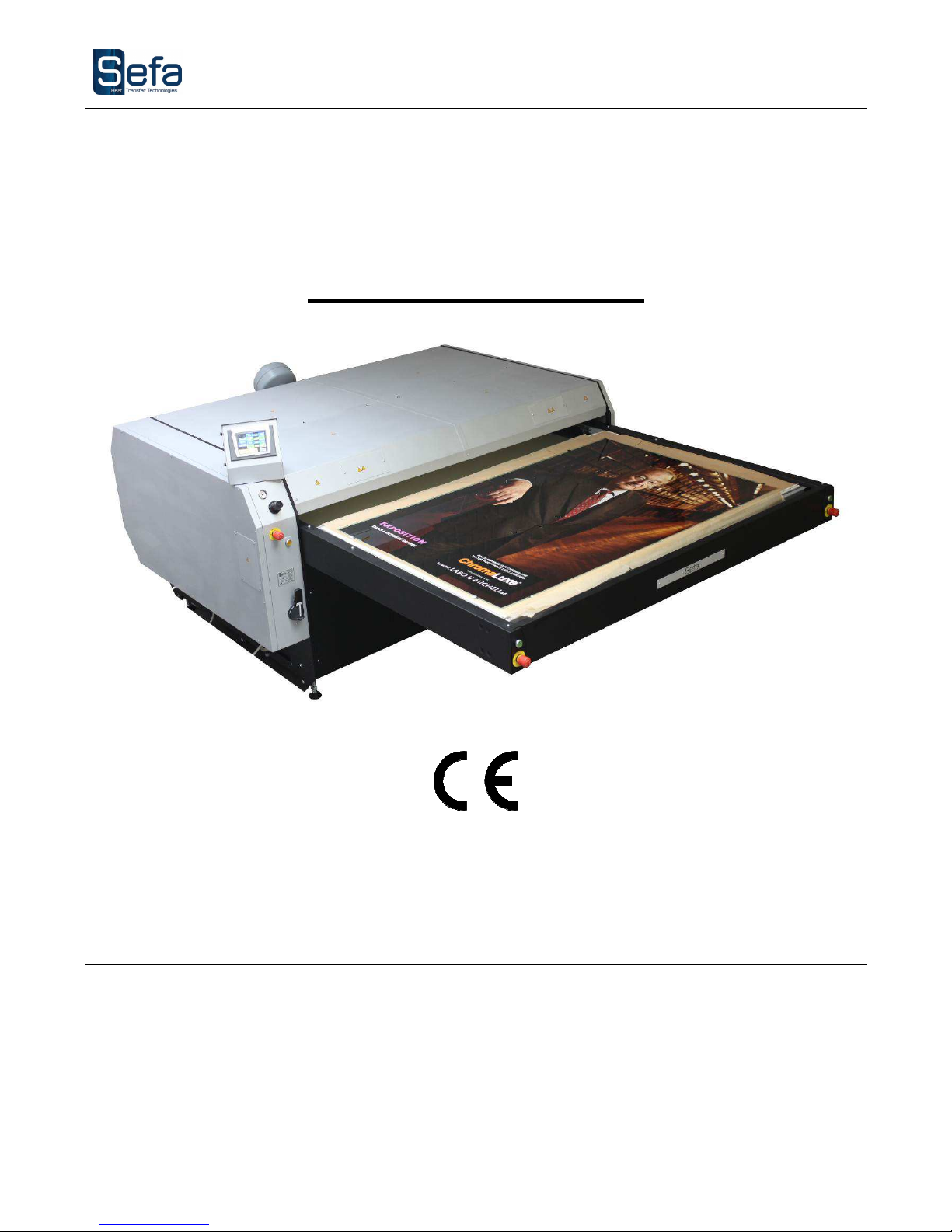
INSTRUCTION MANUAL
SUBLIMAX 1812
S.E.F.A®
Z.I PASTABRAC
11260 ESPERAZA
FRANCE
Tel: 33 (0)4.68.74.05.89 - Fax:33.(0)4.68.74.24.08
Email: [email protected]
Page 2

V0116
Page 2
INDEX
INDEX .......................................................................................................................................................... 2
I. CONDITIONS OF GUARANTEE ............................................................................................................ 3
II. SPECIFICATIONS ................................................................................................................................ 4
III.
OVERVIEW ..................................................................................................................................... 5
IV. USING THE MACHINE ......................................................................................................................... 6
1. SAFETY .................................................................................................................................................. 6
2. INSTALLATION ....................................................................................................................................... 8
A. Mounting arm assembly left .............................................................................................................................. 8
B. Mounting arm assembly right ............................................................................................................................ 9
C. Mounting the support bar ............................................................................................................................... 10
D. Removing motor pinion .................................................................................................................................. 10
E. Reassembly motor pinion ................................................................................................................................ 11
F. Mounting free pinion set ................................................................................................................................. 12
G. Mounting extraction fan .................................................................................................................................. 13
V. DESCRIPTION OF THE OPERATING CYCLE ....................................................................................... 14
1. COMPLETE CYCLE ................................................................................................................................. 14
2. OPERATING WITH THE TOUCH SCREEN ................................................................................................ 15
3. PRESS SETTINGS .................................................................................................................................. 18
A. TEMPERATURE SETTING ................................................................................................................................ 18
B. TIME SETTING .............................................................................................................................................. 18
4. PROPPING THE PRESS FOR START CYCLE CONFIGURATION ................................................................... 18
5. ASPIRATION TIMER SETTING ............................................................................................................... 18
VI. ELECTRIC DIAGRAM ......................................................................................................................... 19
VII.
PNEUMATIC DIAGRAM ................................................................................................................. 22
VIII. ELECTRICAL PANEL ...................................................................................................................... 23
IX. MAINTENANCE .................................................................................................................................. 24
1. SERVICING ........................................................................................................................................... 24
2. PARTS SUBJECTED TO WEAR AND TEAR ............................................................................................... 24
3. QUICK REPAIR ADVICES ....................................................................................................................... 25
4. MAINTENANCE LOG .............................................................................................................................. 26
Page 3
V0116
Page 3
I. CONDITIONS OF GUARANTEE
• The guarantee period starts the day of putting the equipment into service at the user’s place, materialized by the
return of the guarantee bill for a duration of two years, 8h per day meaning about 3000 hours.
• The guarantee is strictly limited to our equipments, against the defects of matter and execution, with the buyer’s
responsibility to prove the known defects.
• Our responsibility is limited to the obligation to rectify or replace free of charge the parts acknowledged as faulty
by ourselves, and there will no claim for any indemnity whatever the reason given.
• Parts replaced under the guarantee:
- remain our property
- are the subject of an invoicing of deposit
• A credit of cancellation is activated as soon as the faulty parts are returned.
The return will have to occur ONE MONTH MAXIMUM after the intervention
THE GUARANTEE DOES NOT COVER :
• The retail consumables such as:
- Fuses, bulbs, joints, flexible devices, covers, nozzles, filters.....
- The supplies, which are not our own manufacturing, undergo the guarantee of their manufacturer.
THE GUARANTEE DOES NOT APPLY :
• To replacements, nor repairs which would result from normal wear and tear of apparatus and machines, of
deteriorations and accidents coming from negligence, defect of monitoring and maintenance, defective use or
modifications without our written agreement.
• In case of vice coming from the material supplied by the buyer, or a design imposed by the latter.
• To repairs which would result from deteriorations or accidents occurred during transport.
• To operations of maintenance and adjustments inherent in the use of the machine, and indicated in the
maintenance manual, such as:
- adjustments of intermediaries
- screwing of piping, etc…
For the pneumatic machines, any trace of detergent oil in the pneumatic circuit inhibits
the conditions of guarantee previously mentioned.
For any technical information or spare parts orders,
please give the reference number of the machine as well as its serial number
Page 4
V0116
Page 4
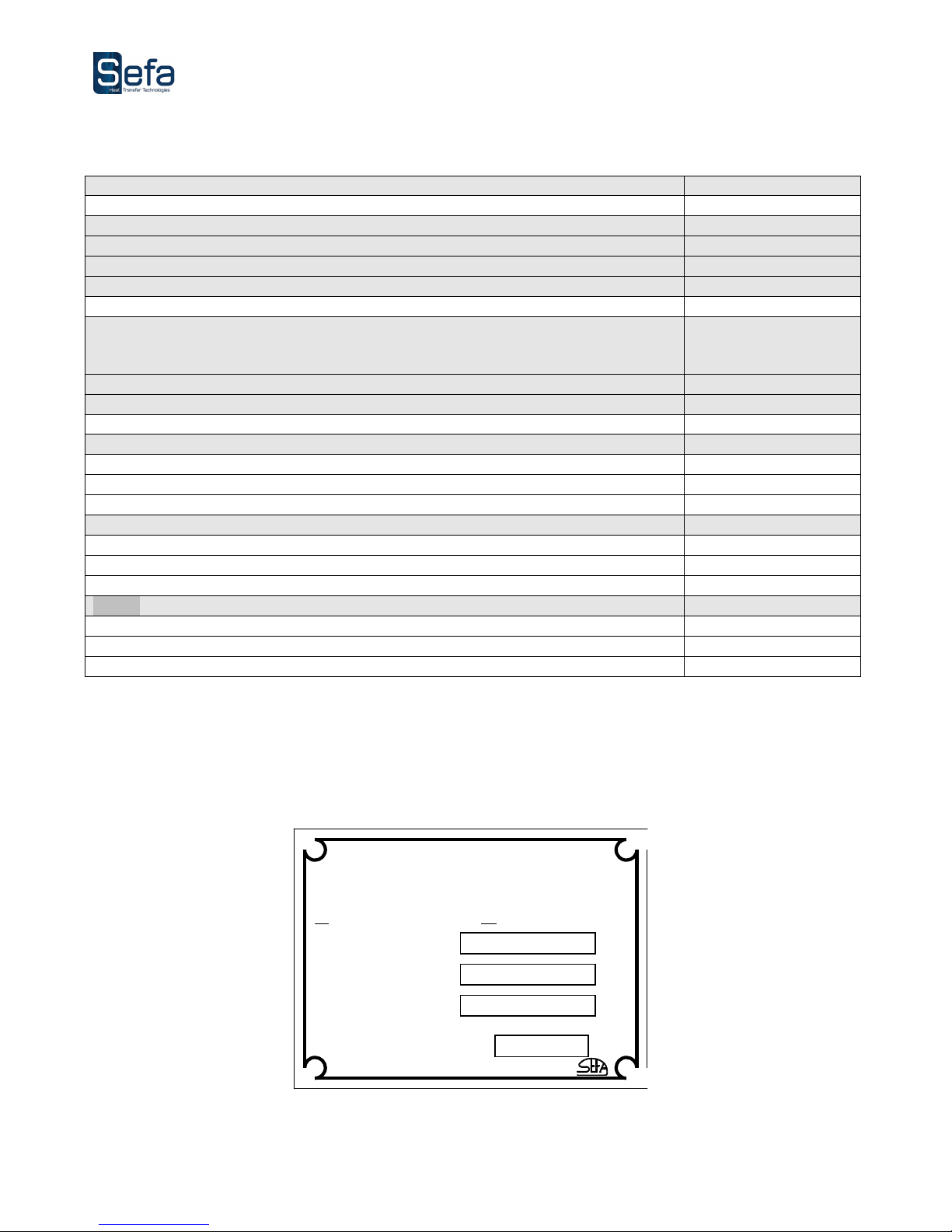
II. SPECIFICATIONS
Weight in running orde
r
1000 kg
Height
1370 mm
Depth
2990 mm
W
idth
1970 mm
Dimension of the heating plate
1800 x 1200 mm
Electric power supply
400 V +
neutral and
earth connections
50/60 Hz
Power
30 KW
Amperage
46 A
Working pressure
Mini
4 bars
Maxi
8 bars
Thermoregulator
Accurate to
+/- 5%
Range of control
0 à 220°C
Timer
Accurate to
+/- 2%
Range of control
1 à 30 mn
Non contractual document: according to the technical progress, we reserve the right to modify the characteristics of
our products.
Some of these characteristics are recalled on the nameplate you will find on the machine.
Made in France.by
MODELE
PUISSANCE
Tel
:+33.(0)4.68.74.05.89
Fax :+33(0)4.68.74.24.08
S.E.F.A ®
Z.I PASTABRAC
11 260 ES
PERAZA
–
(France)
N° de Série
Année de Fab.
Page 5
V0116
Page 5
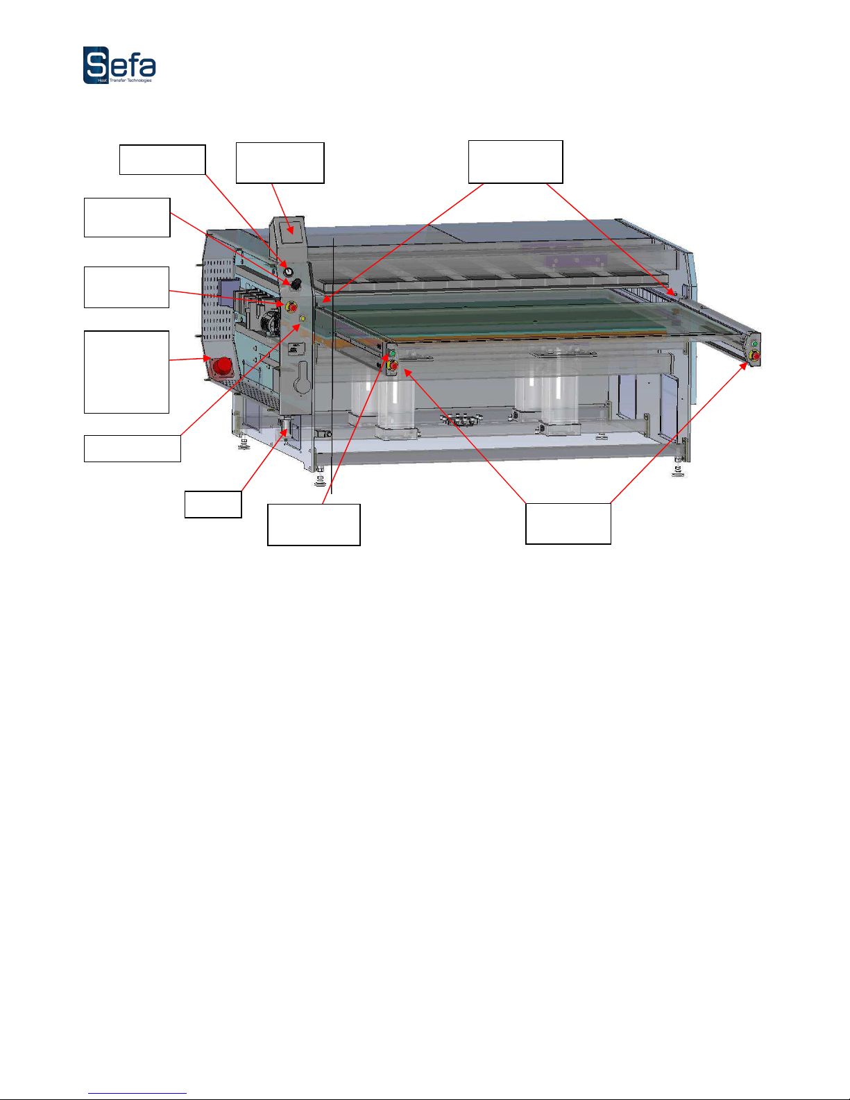
III. OVERVIEW
This heat press machine is standard to the labour laws to ensure the security of the user.
It is designed to ensure the production with total reliability.
This press was designed for an operator working in front of the machine.
Touch
screen panel
Reset
Cycle start
button
Emergency
stop
Pressure
regulator
Filter
Emergency
stop
Main plug
(400V)
Neutral and
earth
connections
Manometer
Safety cells
Page 6
V0116
Page 6
IV. USING THE MACHINE
The press SUBLIMAX 1812 was designed for the application of transfers of all grades.
This equipment has been tested in our workshops to get a one year warranty against manufacturing
defects.
Power settings, mechanical and pneumatic submitted by our technicians in the workshop as well as the
security established on the machine should never be changed. Otherwise, the SEFA ® company will
deny all responsibility on potential problems associated with said machine.
Before starting any pressing operation, it is recommended that you read the safety instructions and the
instructions for use.
The press should be used by an authorized person and having been informed of the risks that may be
caused by improper use of the equipment
1. SAFETY
THIS EQUIPMENT IS DESIGNED FOR SINGLE USE ONLY
USE BY QUALIFIED STAFF
ONLY
I
nternationa
l Symbols
O
OFF
HOT SURFACE
I
ON
ELECTROCUTION RISK
DANGER, WARNING
You will find most of these symbols on the SEFA equipment.
Important point for security :
Don’t touch the hot parts of the equipment while in use.
During handling action, ensure the operator does not take any risk in terms of burns, electrocution or
other.
Proceed with a daily inspection of the machine before starting the production .
Make sure nobody is around or near the machine before you start it up.
If the machine does not work properly, shut down immediately all energy supplies and search for the
cause by using the book’s « Maintenance » chapter.
Page 7
V0116
Page 7
Security devices installed on the machine
The protections and security devices should not be modified.
They should be restored in case of removal for maintenance work.
The must be maintained in good running order during the production.
The press SUBLIMAX 1812 is equipped with security systems preventing from pinching risk.
The main security devices are:
The emergency off
Located on the left side of the console of the machine as well as on both arms by pressing one of them the machine
is switched off and the cold plate goes down.
The photocell
Situated to the front of the heating plate, it ensures that the operator is remote from the heating plate during the
rise of the pressing plate.
Checking the operation of the safety device :
• Users have to verify the proper functioning of the various safety devices daily.
Page 8
V0116
Page 8
2. INSTALLATION
USE BY QUALIFIED STAFF
ONLY
• Lower the machine from its packaging with a forklift
• Place the machine on its operating location.
• Remove all items related to packaging: paper, cardboard, plastic film, wood, etc. ...
• Put the machine level (if necessary) by turning the adjustable feet in height.
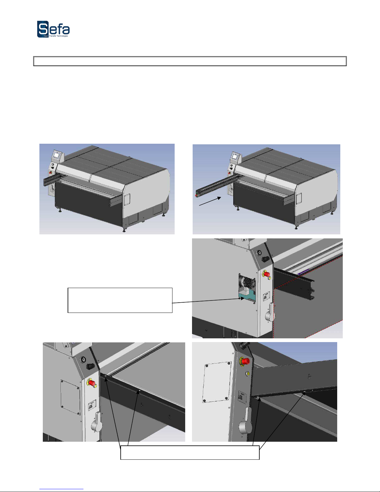
• Mount the machine as shown below
A. Mounting arm assembly left
Handing over the hatch for the arm
support cables within the enclosure
Screw and tighten
the 4 screws
M8-
12
curved
Page 9
V0116
Page 9
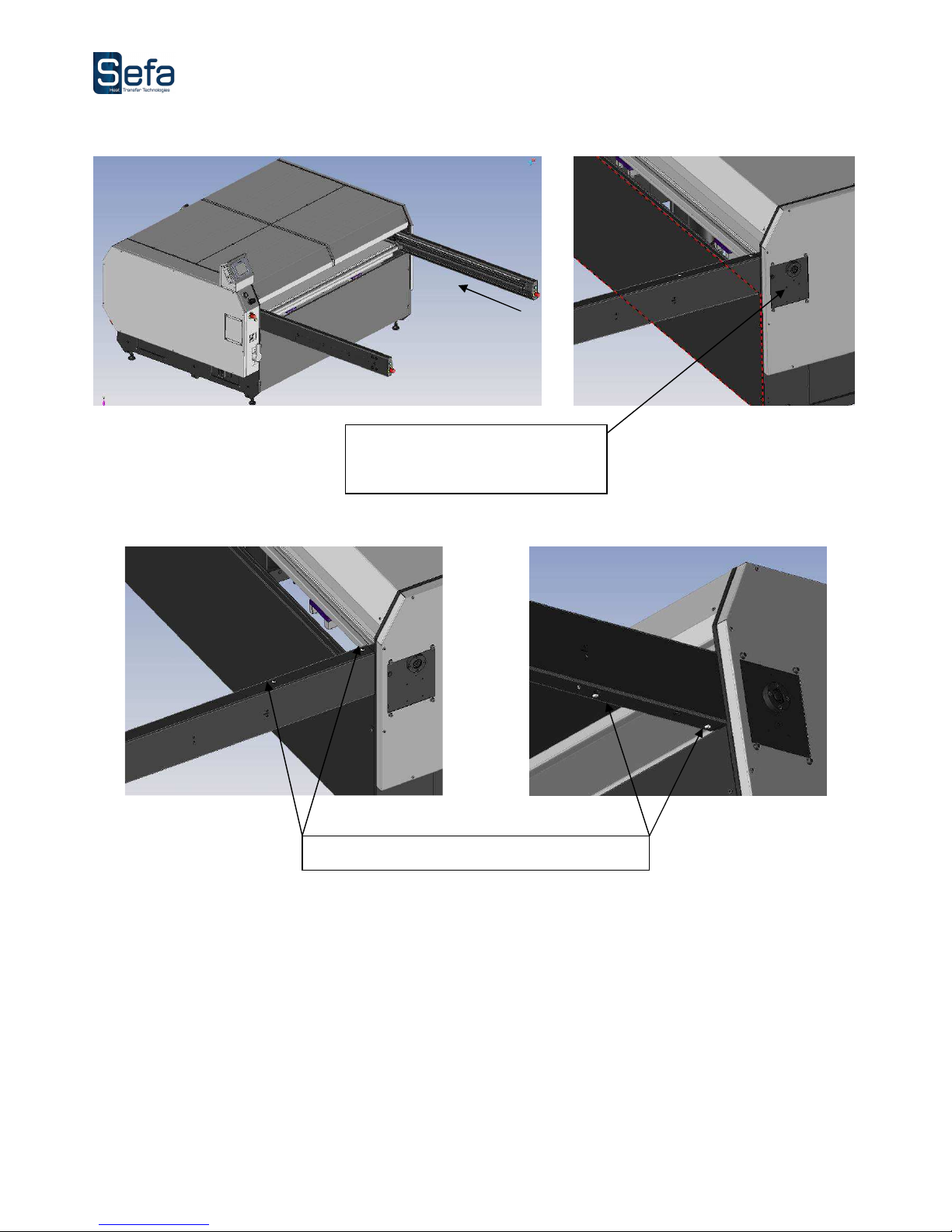
B. Mounting arm assembly right
Handing over the door to
accompany the cables to the arm
inside the cap.
Screw and tighten
the 4 screws
M8-
12
curved
Page 10
V0116
Page 10
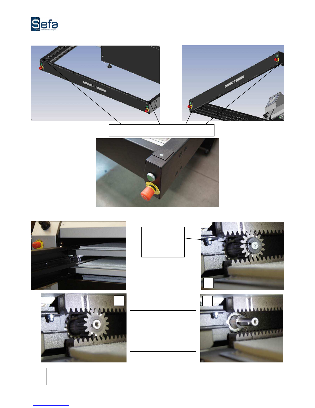
C. Mounting the support bar
D. Removing motor pinion
Unscrew and
remove the
screw TFM5-12
+ Washer.
Remove the motor pinion
pulling. If necessary,
relieve the weight of the
upper frame by slightly
raising.
The frames are now free to move. Manually move the frame over the entire course to ensure that
they slide properly.
1
2 3
Screw and tighten
the 4 screws
curved
M5-12
Page 11
V0116
Page 11
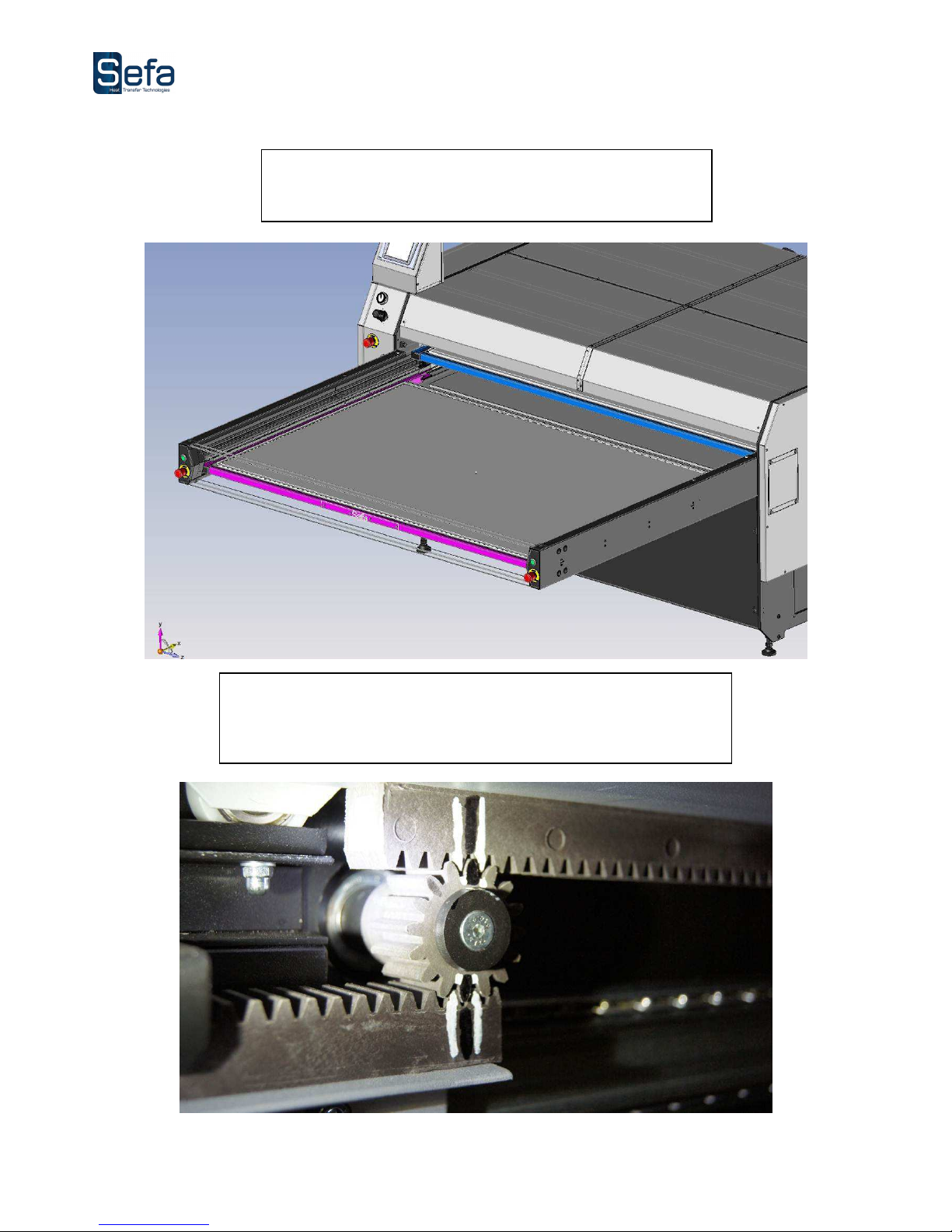
E. Reassembly motor pinion
Position
The upper rear frame (blue in the figure)
And the lower frame at the front (in pink on the drawing)
Reassemble the motor pinion ensuring continuity pins made on both the
pinion and the rack. If necessary, relieve the weight of the upper frame by
lifting slightly.
Then screw and tighten the screw TFM5-12 + washer (removed in step 4).
Page 12
V0116
Page 12
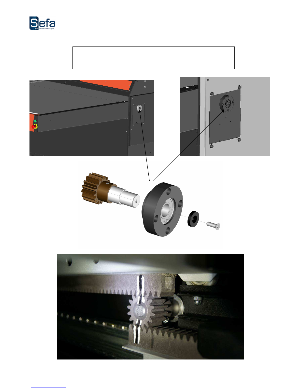
F. Mounting free pinion set
Reassemble the free pinion set through the right door. Ensure continuity
marks made on both the pinion and rack.
And screw the screw TF M5-16.
Page 13
V0116
Page 13
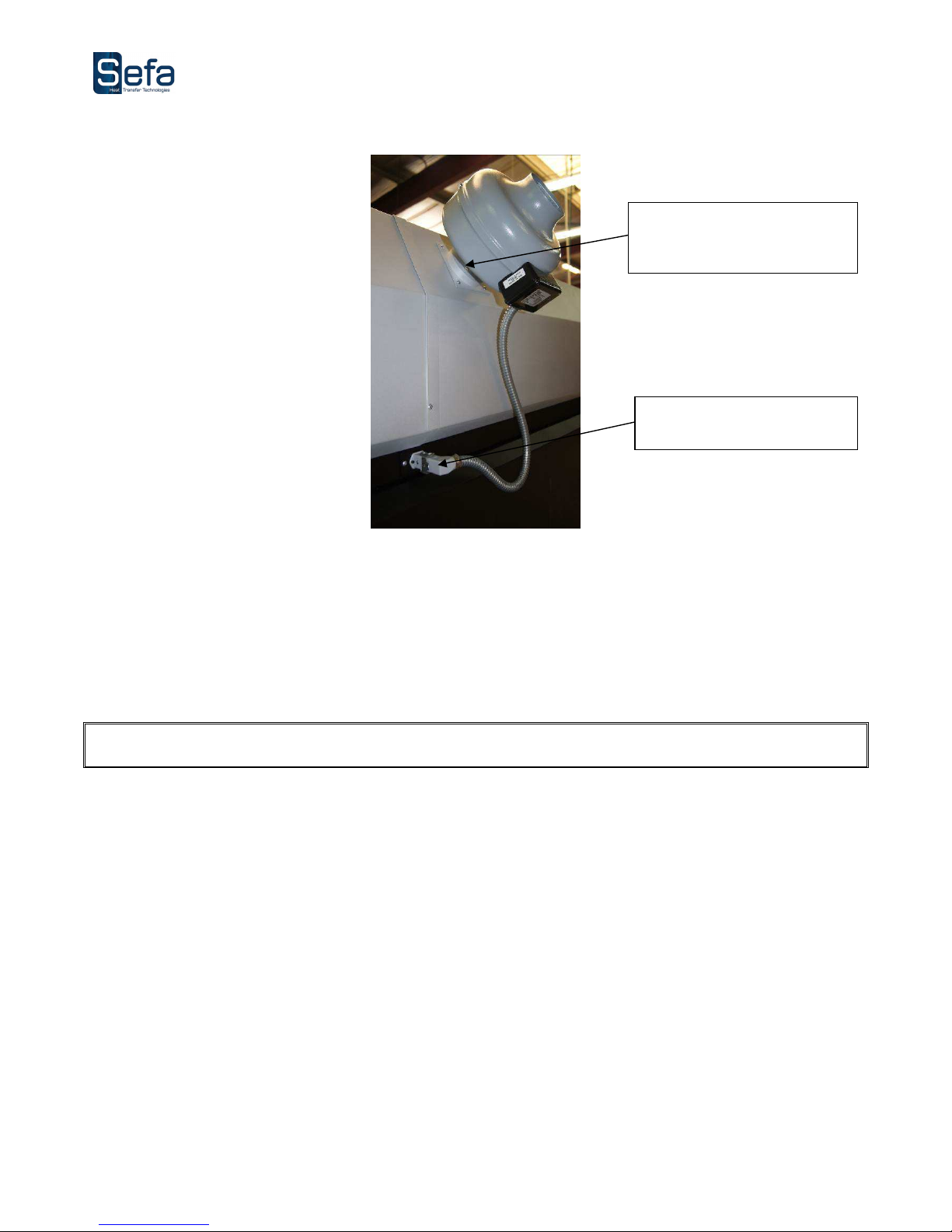
G. Mounting extraction fan
HAVING DONE CORRECTLY THE ASSEMBLY AND POSITIONING OF EQUIPMENT ON THE PLACE OF
OPERATIONS
:
• Electrically connect the press (380 Volt + Neutral + Earth / 50 or 60 Hertz). The red jack is located on the left side of the
machine.
• Connect pneumatic press your compressed air system (3 mini bar, 10 bar). Connect the air filter on the controller (left side
of the machine).
Place the fan on the flange and
screw the 3 screws curved M5-
12
Connect the ventilator plug
Page 14

V0116
Page 14
V. DESCRIPTION OF THE OPERATING CYCLE
1. COMPLETE CYCLE
1. Turn the machine by flipping the power switch located on the left side of the chassis. Press the push
button reset (screen lights up and displays the home page)
2. Press "control" to enter the temperature and time setting.
3. To start a cycle, carts must always lie in the extreme position, if that is the case, see SETTING MACHINE.
4. Set the temperature on the touch screen (to define the following type of application),
See § the TEMPERATURE ADJUSTMENT page 18
5. Set time pressing on the touch screen (to be defined for the type of application)
See § SETTING TIME page 18
6. Adjust the pressure by the regulator on the front of the electrical box (reading on the pressure gauge)
7. Place the item to be marked on the bottom plate,
8. Adjust the transfer sheet,
9. Press the "Cycle Start" and hold off the truck green button : the carriages move,
10. The cold plate rises and presses the heating, activating the timer board.
11. At the end of the timer countdown, cold plate descends down position.
12. Repeat the process from 6 if the settings do not change (except No. 3)
During the cycle: On the touch screen "Stop pressing" allows interrupt pressing and lowers the pressure plate
Pressing the button “cycle start” stops the pressing, lowers the pressure plate and reverse the tray carts.
Page 15
V0116
Page 15
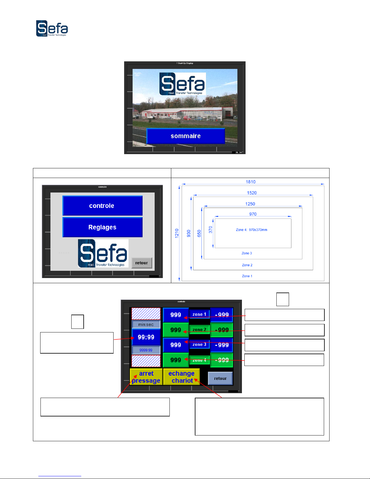
2. OPERATING WITH THE TOUCH SCREEN
Summary
Dimensions
of the
4 areas
Control
T° adjustment area 1
T° adjustment area 2
T° adjustment area 3
T° adjustment area 4
Pressing time adjustment
interrupt the pressing cycle without moving
decks
During pressing: interrupts the press and trade
decks.
Off pressing: exchange decks.
2
1
Page 16
V0116
Page 16
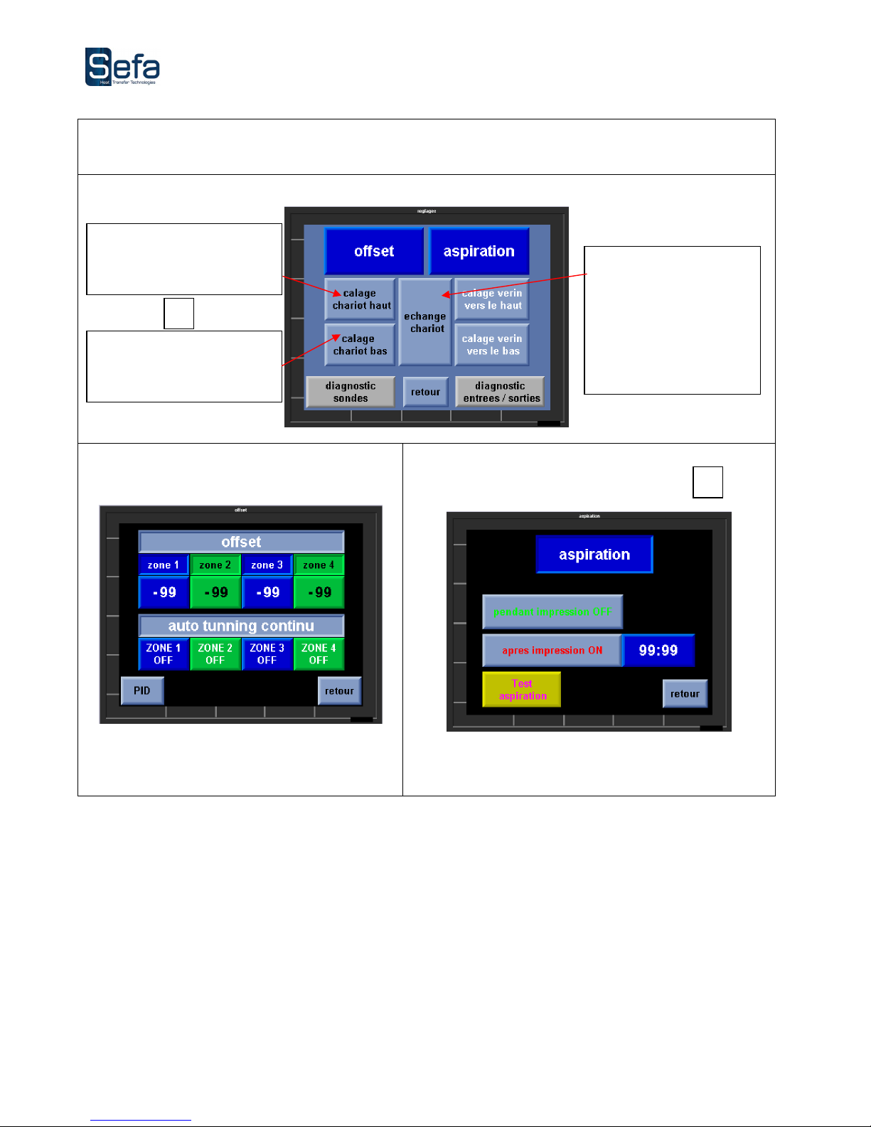
Settings
Offset
Allows the offset of each zone.
Aspiration
Allows the aspiration motor test and adjust its operation
during the cycle
During the pressing :
stops the pressing cycle
and switches decks.
Off pressing : switches
decks.
Allows to correctly reposition
the deck up under the
heating plate
Allows to correctly reposition
the deck down under the
heating plate
3
4
Page 17
V0116
Page 17
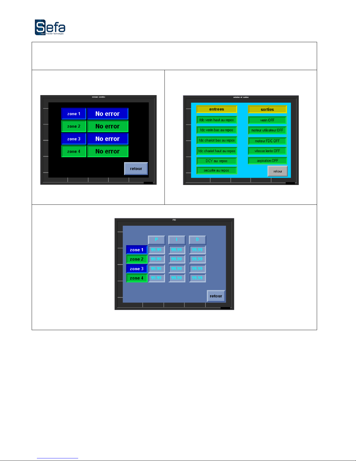
Diagnostics
Probe diagnostic
Indicates the faulty probe and the type of error
I/O diagnostic
Indicates the status of sensors and actuators
Shows the parameters used to control each area
Page 18
V0116
Page 18
3. PRESS SETTINGS
USE BY QUALIFIED STAFF
ONLY
A. TEMPERATURE SETTING
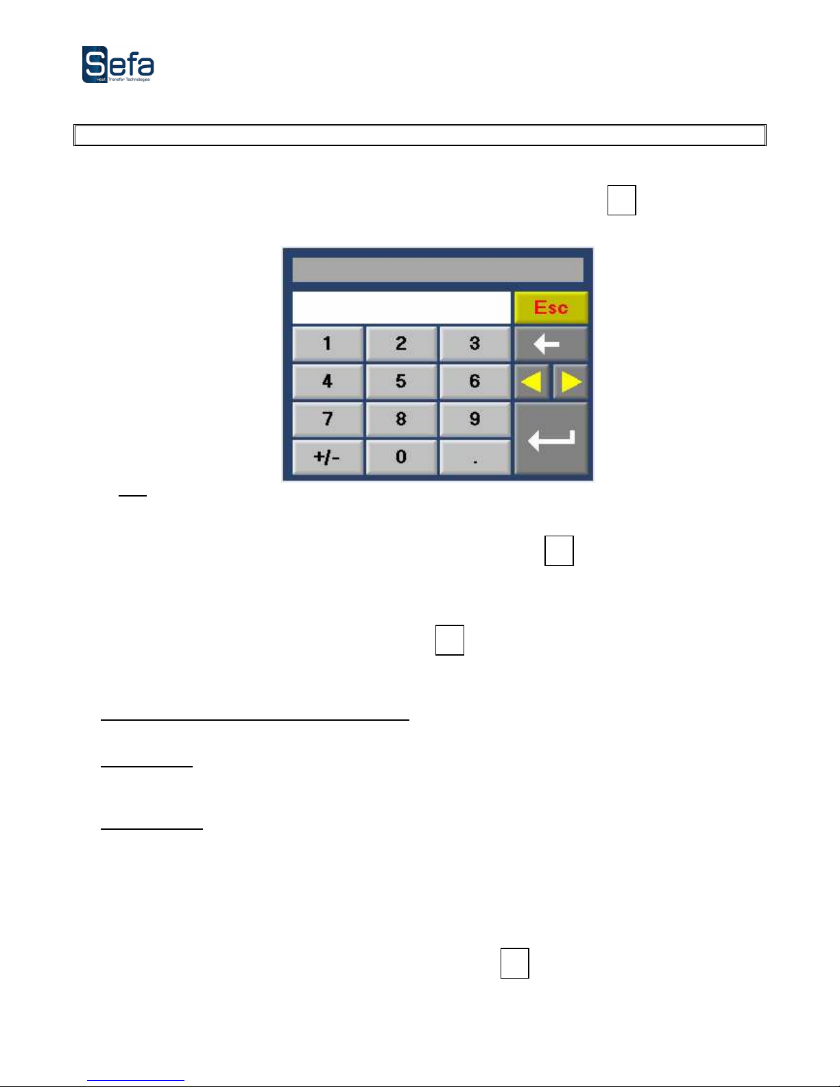
Set the temperature for each area, refer to the operation of the touch screen, § Controls, note
Pressing the control button brings up the following temperature display :
Nota : This screen is the same for all digital input.
B. TIME SETTING
Set the pressing time, refer to the operation of the touch screen, § Controls, note
Pressing the control key pressing time that appear identical to that of the temperature setting screen.
4. PROPPING THE PRESS FOR START CYCLE CONFIGURATION
Refer to the operation of the touchscreen § Settings, note
When first unpacking or after pressing one of the safety devices, the following points need to be validated before a
restart cycle :
Unlock 3 emergency stop buttons (if required) :
If an emergency stop button is pressed, you must unlock it by turning in the clockwise direction.
Reset button :
After pressing one of the safety devices, the machine is in "default position", it must be reset by pressing the
(bright yellow) reset button.
Prop the press :
To start a cycle, the decks must be in extreme position. On the touch screen, adjust the buttons "deck up" and
"deck down" for correctly reposition decks.
Nota : Return-is then made at a slow speed to avoid the risk of damage to the machine.
If these three points are validated, the machine is now in "start cycle" configuration.
5. ASPIRATION TIMER SETTING
Refer to the operation of the touch screen, § Aspiration, note .
The aspiration can be activated during the pressing cycle and / or for a time selected at the end of pressing.
4
3
2
1
Page 19
V0116
Page 19
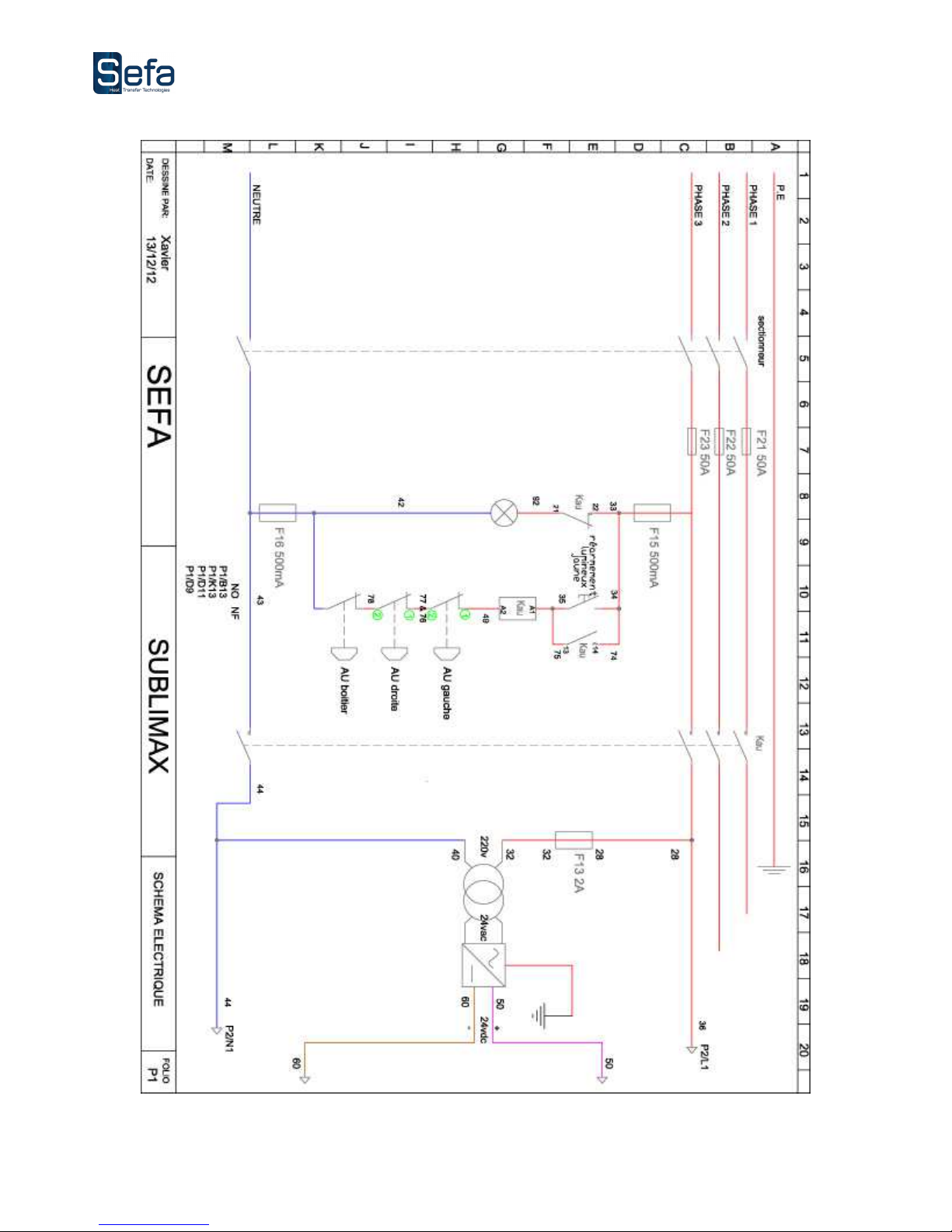
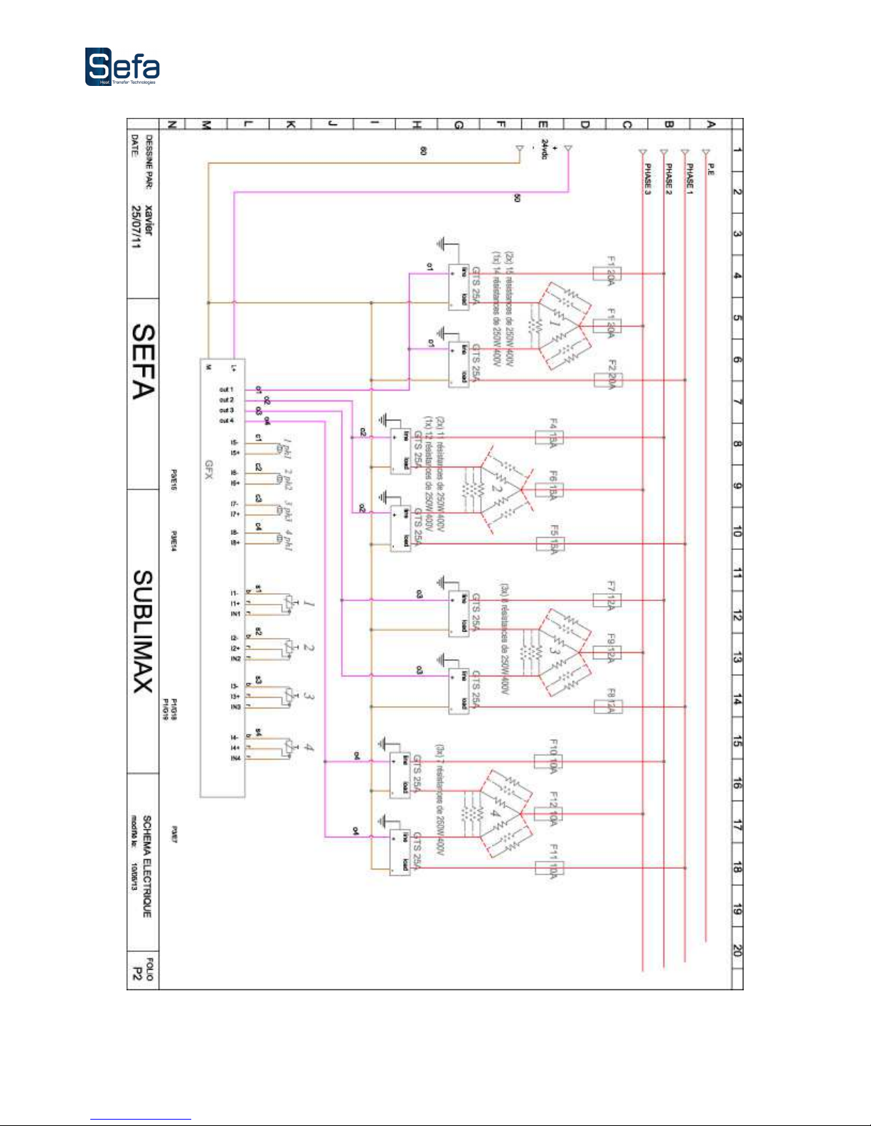
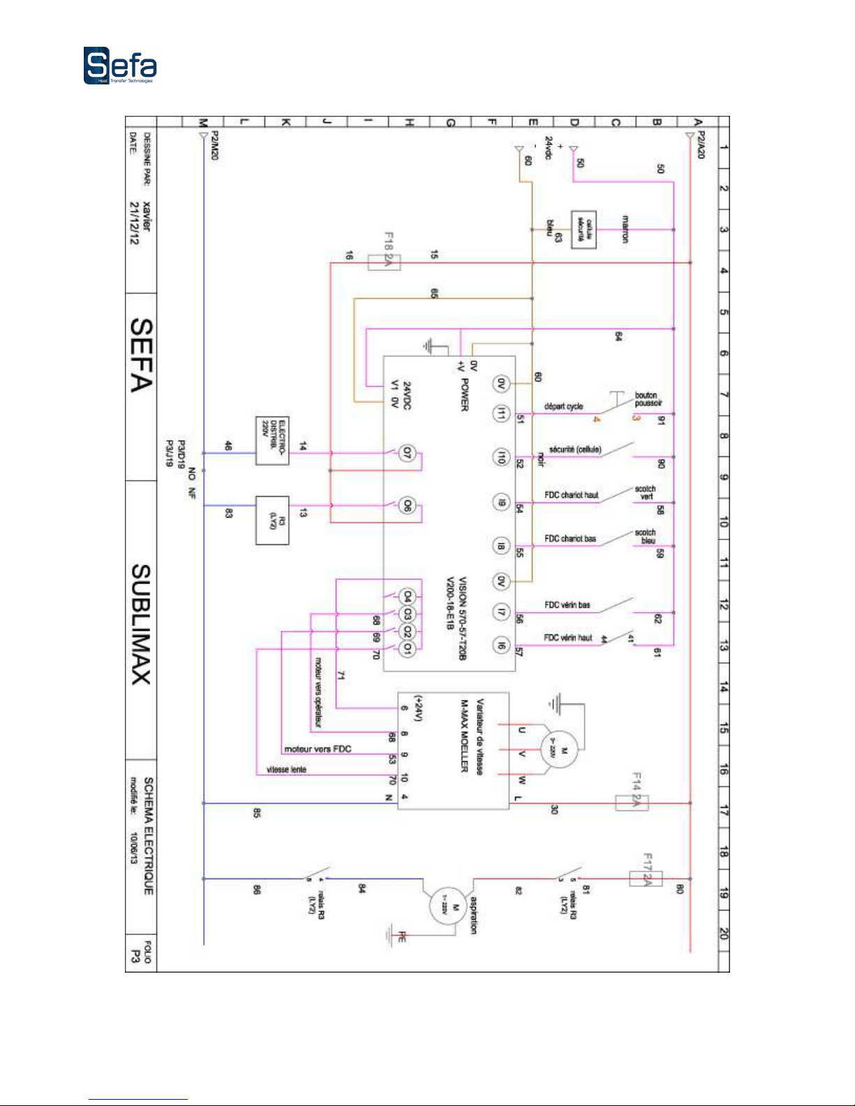
VI. ELECTRIC DIAGRAM
Page 20
V0116
Page 20
Page 21
V0116
Page 21
Page 22
V0116
Page 22
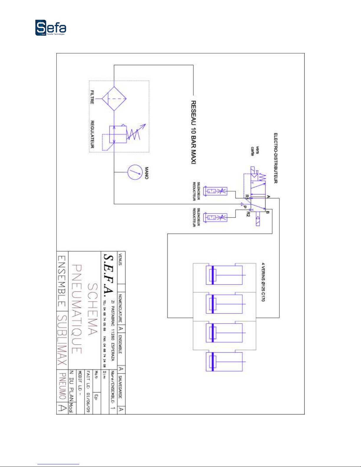
VII. PNEUMATIC DIAGRAM
Page 23
V0116
Page 23
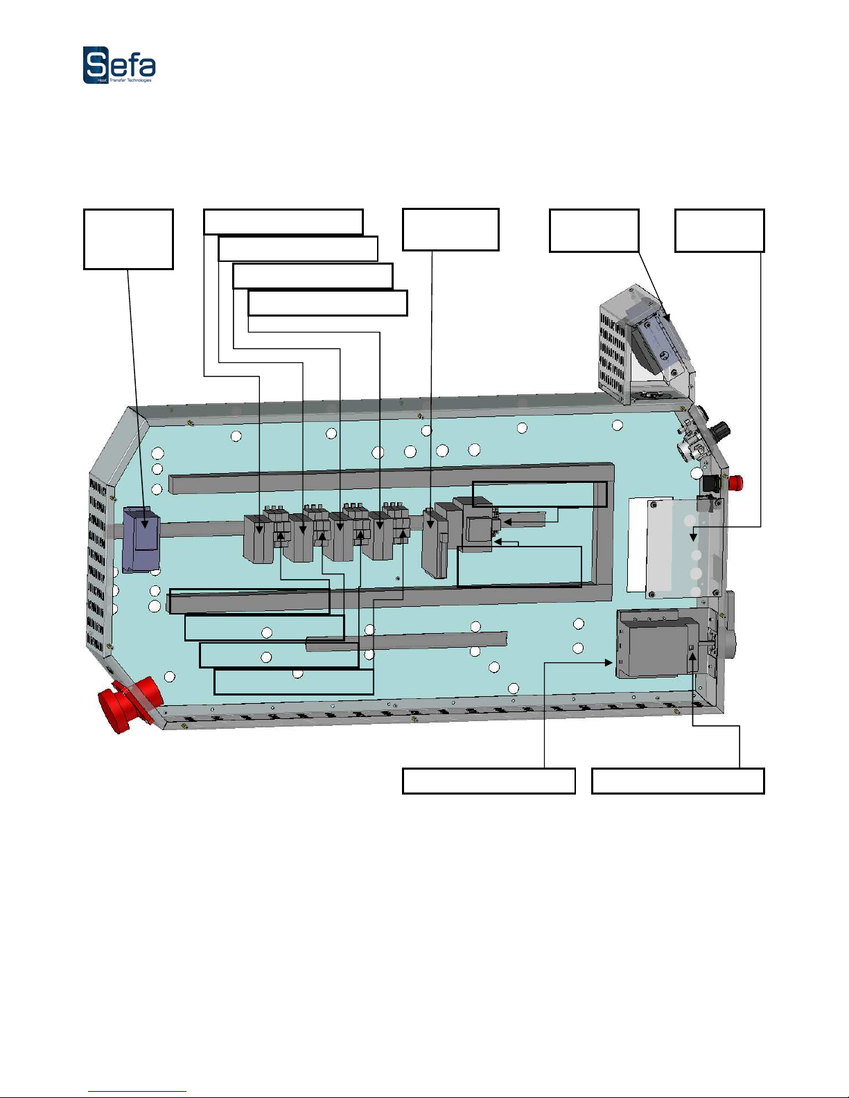
VIII. ELECTRICAL PANEL
Frequency
inverter
Static relay
zone 1
Static relay
zone 2
Static relay
zone 3
Static relay
zone 4
4 zone
regulator
Touch
screen
Moto
r
reducer
Fuseholder
zone 1
Fuseholder
zone 2
Fuseholder
zone 3
Fuseholder
zone 4
A
spiration
relay
Emergency stop
contactor
Disconnecting switch
Main fuses
Page 24
V0116
Page 24
IX. MAINTENANCE
USE BY QUALIFIED STAFF ONLY
ANY SERVICING INTERVENTION MUST BE DONE WHEN THE MACHINE IS OFF AND LOCKED
(ELECTRIC AND PNEUMATIC ENERGIES UNPLUGGED)
1. SERVICING
Heat transfer press SEFA ® require little maintenance. To ensure proper operation, follow the
preventive guidelines listed below.
Do not heat objects that could damage or even cut the silicon rubber or damaging the Teflon surface
DAILY
:
Check the air intake on the right side, the purge filter if there is too
much condensation.
MONTHLY
:
Check
and lubricate the
axes
if necessary
.
ACCORDING TO THE USE
:
Change
felt every 6 months
.
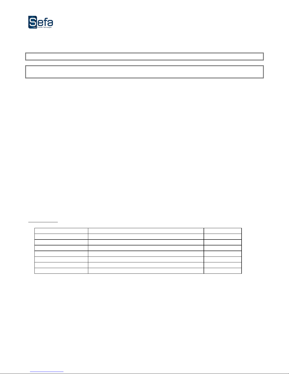
2. PARTS SUBJECTED TO WEAR AND TEAR
For all orders: specify the reference, description and the quantity you want.
Reference Description Quantity
FEU-006 NOMEX FELT Ep. 9mm width 2M 1600gr/M² sold by ML
FEU-030 NOMEX FELT Ep. 6mm width 2M 4000gr/M² sold by ML
TOI-001 NOMEX FABRIC 230gr/M² width 1,65M (ecru color) sold by ML
SON-PT100 PT100 CONTACT PROBE special Sublimax (fixing eyelet) 1
Page 25
V0116
Page 25
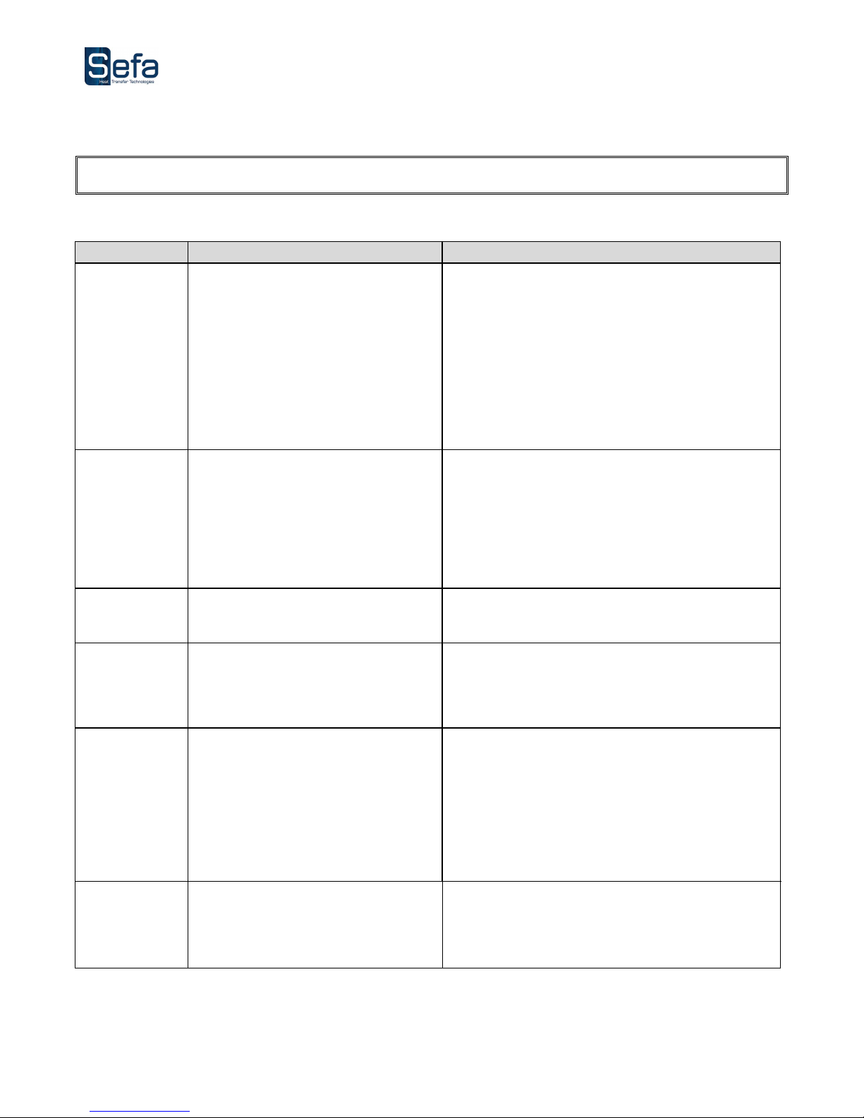
3. QUICK REPAIR ADVICES
ANY SERVICING INTERVENTION MUST BE DONE WHEN THE MACHINE IS OFF AND LOCKED
(ELECTRIC AND PNEUMATIC ENERGIES UNPLUGGED)
SYMPTOMS
POSSIBLE BREACKDOWNS REPAIRS
The machine will
not switch on
The plug is not connected
The switch is not on
Fuse out of order
Fuse board out of order
The is a fault in the display unit
Check the mains and see if the machine is
connected.
Put the main On/Off switch on 1.
Check the fuses in the fuse-holders located on the
bottom left of the control board (80mAT)
Check that the cabling is connected. In that case,
the display unit is out of order
The plate does
not heat
Faulty resistances
Problem with static relay
Temperature set too low
Check the connections and the state of the
electrical wiring. Contact your distributor for
disassembling the heating plate.
Check connections and the state of electrical wiring.
Contact your distributor.
In order to change this value, see Chapter
“Settings”
The plate is
overheating
Problem with the probe or the
mainboard
See the messages displayed on the touch screen.
Contact your distributor.
The timer does
not work
The « plate up » magnetic detector
has not been actuated or is faulty
Check state on touch screen « I/O ». Check
connections.
The cold plate
does not rise
Leak on the cylinders
The electro-distributor is faulty
Compressed air pressure is
insufficient
Check its state on the « diagnostic » screen.
Contact your distributor.
Check connections. Contact your distributor for
changing if it’s necessary.
Check if the pressure on your network is upper than
2 bars.
The cycle does
not start. The
carriages do not
move.
The carriages are not set in correct
position
Press the setting button until the carriages come to
a complete standstill.
Page 26

V0116
Page 26
4. MAINTENANCE LOG
The control and maintenance operations indicated in this table must be done regularly so as to check
the functioning state and the reliability of the press.
Date
Number
of hours
Pressure
control
Air filter
control
Air
Cylinder
control
Rubber
state
Resistors
control
Changed
parts
Observations
In order to facilitate the filling of the table, it may be useful to use the following code:
C: Control N: Clean R: Replace
 Loading...