

Page 1
INSTRUCTIONS MANUAL
iCAP 2 / iLOGO
BY SEFA
Distributors
SEFA
Z.I. Pastabrac 11260 Esperaza
Tel : +33(0)4 68 74 05 89
Fax : +33(0)4 68 74 24 08
email : [email protected]
www.sefa.fr
CHEMICA
8 rue Auguste Poncetton 42000 Saint Etienne
Tel : +33(0)4 77 49 20 90
Fax : +33(0)4 77 25 79 82
email : [email protected]
www.chemica.fr
Page 2

V0414
Page 2
INDEX
INDEX .......................................................................................................................................................... 2
I. CONDITIONS OF GUARANTEE ............................................................................................................ 3
II. ASSEMBLY DRAWING ......................................................................................................................... 4
III. Technical Parameters ..................................................................................................................... 5
IV. USING THE MACHINE ......................................................................................................................... 5
1. SAFETY .................................................................................................................................................. 6
2. INSTALLATION ....................................................................................................................................... 6
3. CAP HEATER AND PLAIN HEAT PLATEN EXCHANGE .................................................................................. 7
V. OPERATION PROCESS ........................................................................................................................ 8
1. SET TEMPERATURE REQUIRED ............................................................................................................... 8
2. SET TIME REQUIRED .............................................................................................................................. 8
3. SET PRESSURE REQUIRED ...................................................................................................................... 8
4. PRINTING METHODS .............................................................................................................................. 9
5. RECOMMENDATIONS .............................................................................................................................. 9
VI. CIRCUIT DIAGRAM ........................................................................................................................... 10
VII. MAINTENANCE ............................................................................................................................. 11
1. SERVICING ........................................................................................................................................... 11
2. QUICK REPAIR ADVICES ....................................................................................................................... 11
3. TROUBLE SHOOTING FOR TRANSFER PRINT QUALITY ........................................................................... 12
4. EXPLOSION VIEW ................................................................................................................................. 12
Page 3

V0414
Page 3
I. CONDITIONS OF GUARANTEE
The guarantee period starts the day of putting the equipment into service at the user’s place, materialized by the
return of the guarantee bill for a duration of one year, 8h per day or 2000 hours.
The guarantee is strictly limited to our equipments, against the defects of matter and execution, with the buyer’s
responsibility to prove the known defects.
Our responsibility is limited to the obligation to rectify or replace free of charge the parts acknowledged as faulty by
ourselves, and there will no claim for any indemnity whatever the reason given.
Parts replaced under the guarantee: remain our property are the subject of an invoicing of deposit
A credit of cancellation is activated as soon as the faulty parts are returned.
The return will have to occur ONE MONTH MAXIMUM after the intervention
THE GUARANTEE DOES NOT COVER :
The retail consumables such as:
- Fuses, bulbs, transformers, joint, flexible devices, covers, nozzles, filters.....
- The supplies, which are not our own manufacturing, undergo the guarantee of their manufacturer.
THE GUARANTEE DOES NOT APPLY :
To replacements, nor repairs which would result from normal wear and tear of apparatus and machines, of
deteriorations and accidents coming from negligence, defect of monitoring and maintenance, defective use or
modifications without our written agreement.
In case of vice coming from the material supplied by the buyer, or a design imposed by the latter.
To repairs which would result from deteriorations or accidents occurred during transport.
To operations of maintenance and adjustments inherent in the use of the machine, and indicated in the maintenance
manual, such as:
- adjustments of intermediaries
- screwing of piping, etc…
For any technical information or spare parts orders, please give the reference number of the
machine as well as its serial number
Page 4
V0414
Page 4
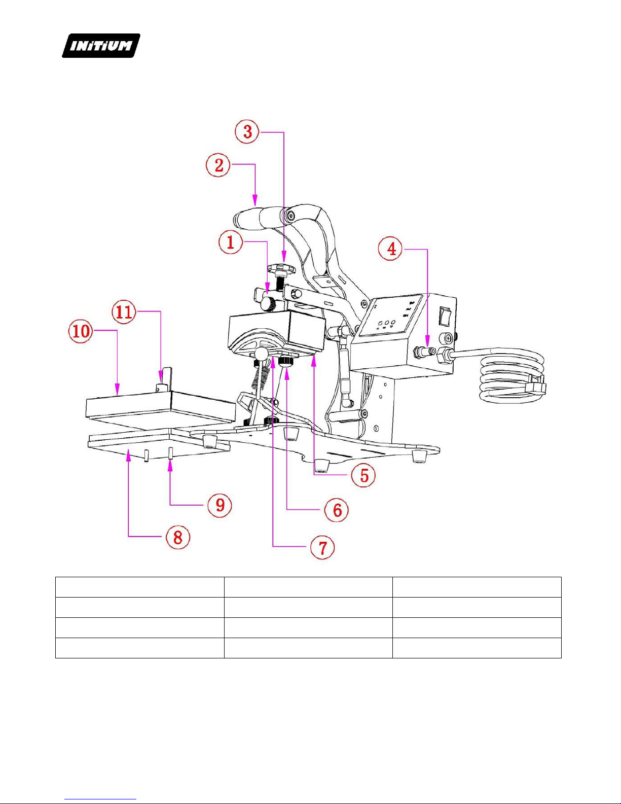
II. ASSEMBLY DRAWING
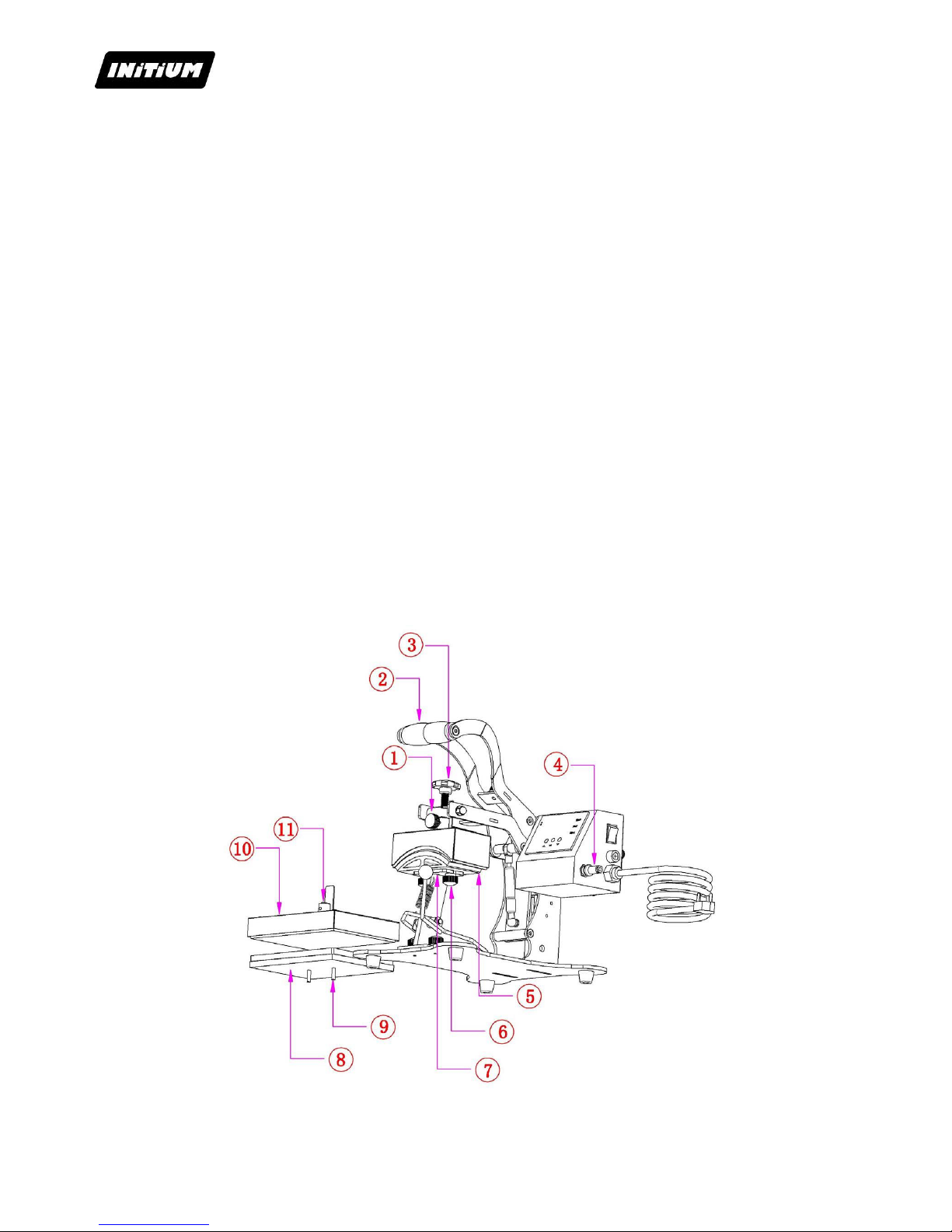
1 Upper Hand Wheel Screw
2 Handle Bar Grip
3 Adjusting Screw
4 Power Cord
5 Cap Heater
6 Under Hand Wheel Screw
7 Supporting Holder
8 Plain Under Plate
9 Fasten Screw
10 Plain Heat Platen
11 Fixing Fittings
Page 5
V0414
Page 5
III. Technical Parameters
Model No.
iCAP 2 / iLOGO
Machine Dimension
380*360*340mm
Heating Elements Size
one normal cap heater & one 15x 20cm heat platen
Printable Articles Max Size
150 x 80mm&150 x 20mm
Voltage
220V/1Phase
Power
0.5KW for cap press; 0.6KW for heat platen
Recommend Setting
180~190C°; 30~40s.
Time Range
0~999s
Maximum Temp
225 C°
Packing Size
48*32*39cm
Gross Weight
19.5kg
IV. USING THE MACHINE
iCAP 2/iLOGO press was designed for the application of transfers of all grades.
This equipment has been tested in our workshops to get a one year warranty against manufacturing
defects.
Power settings, mechanical and pneumatic submitted by our technicians in the workshop as well as the
security established on the machine should never be changed. Otherwise, INITIUM company will deny
all responsibility on potential problems associated with said machine.
Before starting any pressing operation, it is recommended that you read the safety instructions and the
instructions for use.
The press should be used by an authorized person and having been informed of the risks that may be
caused by improper use of the equipment.
Page 6
V0414
Page 6
1. SAFETY
THIS EQUIPMENT IS DESIGNED FOR SINGLE USE ONLY
USE BY QUALIFIED STAFF ONLY
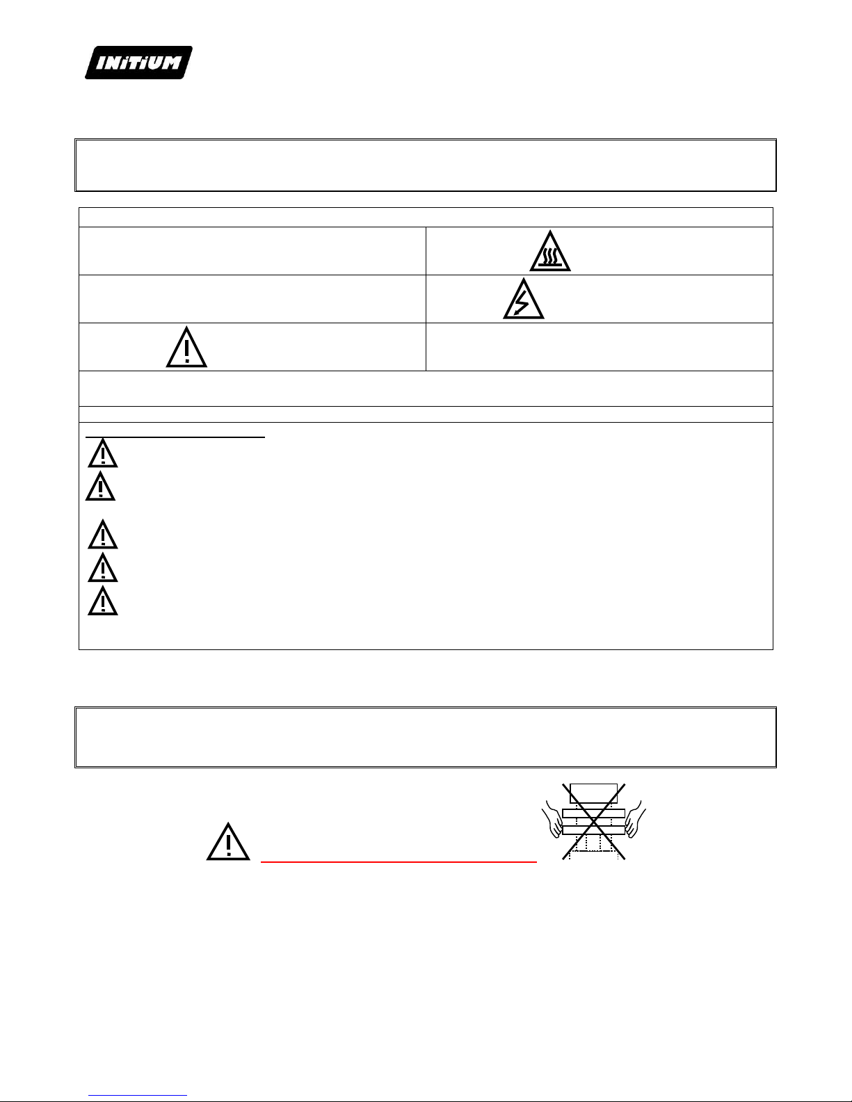
International Symbols
O OFF
HOT SURFACE
I ON
ELECTROCUTION RISK
DANGER, WARNING
You will find most of these symbols on the INITIUM equipment.
Important point for security :
Don’t touch the hot parts of the equipment while in use.
During handling action, ensure the operator does not take any risk in terms of burns, electrocution or
other.
Proceed with a daily inspection of the machine before starting the production .
Make sure nobody is around or near the machine before you start it up.
If the machine does not work properly, shut down immediately all energy supplies and search for the
cause by using the book’s « Maintenance » chapter.
2. INSTALLATION
USE BY QUALIFIED STAFF ONLY
Do not handle the machine by its plates !
Unpack the machine from the box.
Remove all packaging specific items: paper, cardboard, plastic film, wood, etc. ...
Put the machine level (if necessary) by acting on the feet of height adjustment.
Plug the machine electrically
Page 7
V0414
Page 7
3. CAP HEATER AND PLAIN HEAT PLATEN EXCHANGE
1. Unplug the power socket ④, press down the handle bar grip ② with left hand and release
screw bolt ① with right hand.
2. Leave the left hand and the cap platen is now lying on the cap under plate ⑤.
Release screw nut ⑥ to take out the cap press parts.
3. Fix two screws ⑨ in the flat under plate ⑧ and mount it to the support arm ⑦, fasten screw
nut ⑥ to fix the flat under plate ⑧.
4. Place flat heat platen ⑩ above the flat under plate ⑧, use left hand to press down the handle
bar grip ②, and adjust the heat platen mounts and adjustment bolt with right hand, then
tighten the screw ①.
5. Use left hand press down the handle bar grip ② again to make sure the flat heat platen ⑩ is
aligned with flat under plate⑧. Fasten the screw bolt ① and screw nut ⑥ tightly and plug the
power socket ④.
The exchange process is done.
Page 8
V0414
Page 8
V. OPERATION PROCESS
1. SET TEMPERATURE REQUIRED
Turn on power switch.
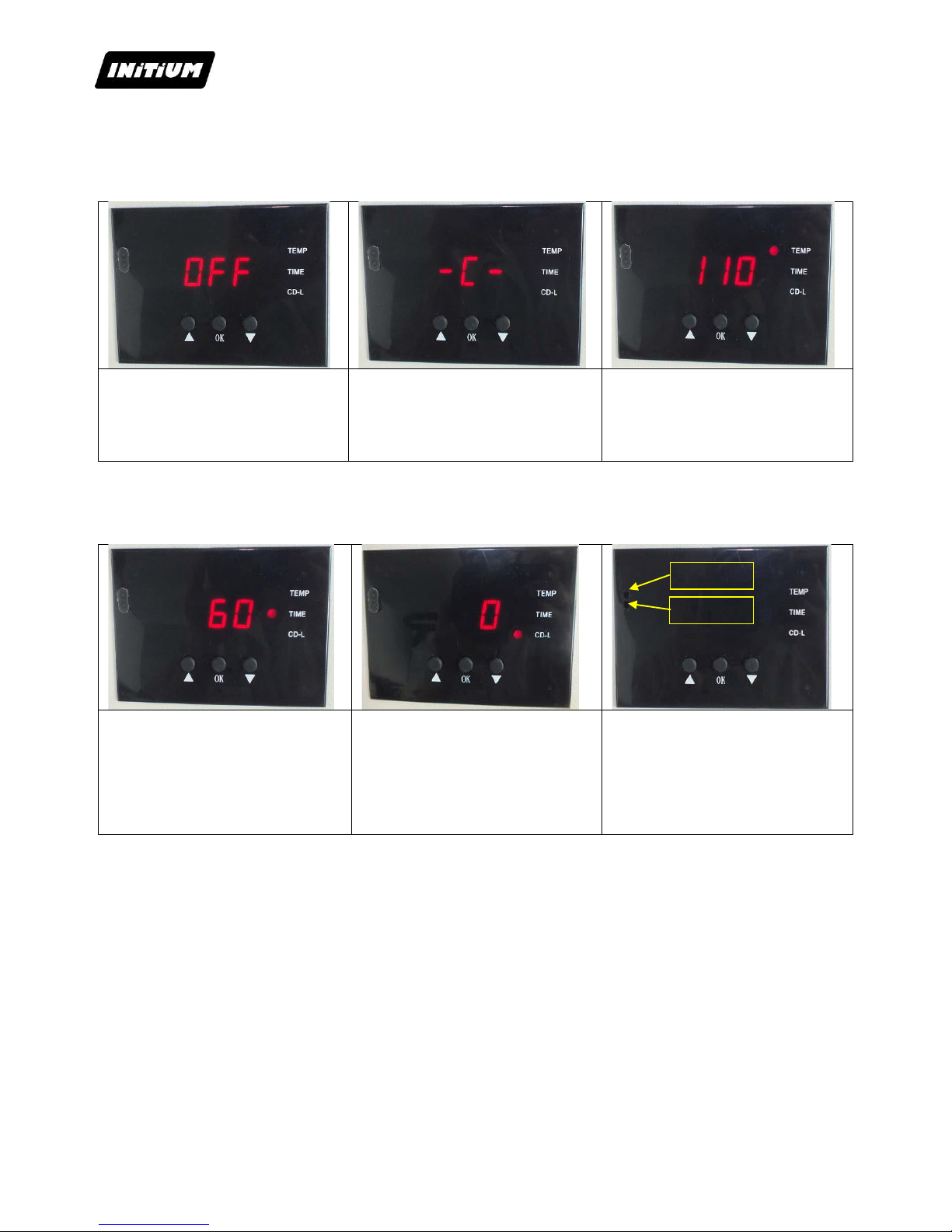
The digital display shows
Press button “OK” , the light is
on (C denotes Celsius). Press
arrows ۸ or ۷ to select “C” or
“F” (F denotes Fahrenheit)
according to your habits
Press button “OK”, the temp light
is on. Select with arrows the
temperature according to different
transfer material (Normally
180.~200° C.)
2. SET TIME REQUIRED
Press button after temperature
setting and the time light is
on. Select with arrows the time
according to different transfer
material
Press button after time setting;
the display shows the temperature
starts to rise. “CD-L” shows the
time counting down during your
transfer.
Note: There are two small port in
front side of the digital display.
If the real temperature is lower
than digital controller shown, you
can adjust the “hot port”; Clockwise
to raise temperature; anticlockwise
to reduce temperature.
3. SET PRESSURE REQUIRED
1) Gently lower the handle (without closing it) to put the heating element in contact with the lower plate tray,
2) Loosen the screws on the front ①,
3) Increase the pressure by turning in the direction of clockwise,
4) Decrease the pressure by turning anticlockwise
5) Tighten the screws on the front ①.
Hot Port
Cold Port
Page 9

V0414
Page 9
4. PRINTING METHODS
Step 1:
Make sure the cord is connected well to the wall socket. Place the cap in the cap heater, and transfer paper with
images facing down the cap, adjust moderate pressure, and power on.
P.S: use heat resistant tape to fix the transfer paper, make sure transfer paper is exactly attached to cap heater;
Step 2:
Set the temperature and time required, then temperature starts to rise.
Step 3:
When the temperature rises to the setting temperature, the buzzer sends out sounds; then press down the cap
heater, (meantime the sounds stop) and starts to transfer.
Step 4:
Then the time counter is on, once time is up, take out the caps. Transfer work finished.
Note: use the similar way when you need to transfer other substrates by using the plain heat platen.
But the printing parameters are different from different items. You can refer to below.
5. RECOMMENDATIONS
1) Cap transfer:
Set temperature: 180°C
Set time: 60 seconds
2) Ceramic Tile transfer:
Set temperature: 210°C
Set time: 240seconds
3) Key Chains & Pearlite Plate transfer:
Set temperature:180°C
Set time: 100~120seconds
4) Mirror (Pearlite plate) and Jigsaw Puzzle transfer:
Set temperature:180°C
Set time: 60~80seconds
5) Wallet (Waist pack) transfer:
Set temperature:180°C
Set time: 120~140seconds
NOTE:
1) Please switch off the machine and unplug the power cord when the machine is not in use.
2) The heater or heat platen will cool down to the room temperature, if heat press stays un-use for more than 30
minutes.
3) For better maintenance of heat press, the maximum setting temperature is 210 degrees C (410 degrees F).
4) To avoid re-heating the first transfer when printing double sided substrates, insert a sheet of cardboard in
between the item, adjust the height to less pressure, then press.
5) Heat platen may pivot slightly back and forth rotationally. This is due to movement allowance within the clamp
assembly, and is normal.
Page 10
V0414
Page 10
VI. CIRCUIT DIAGRAM
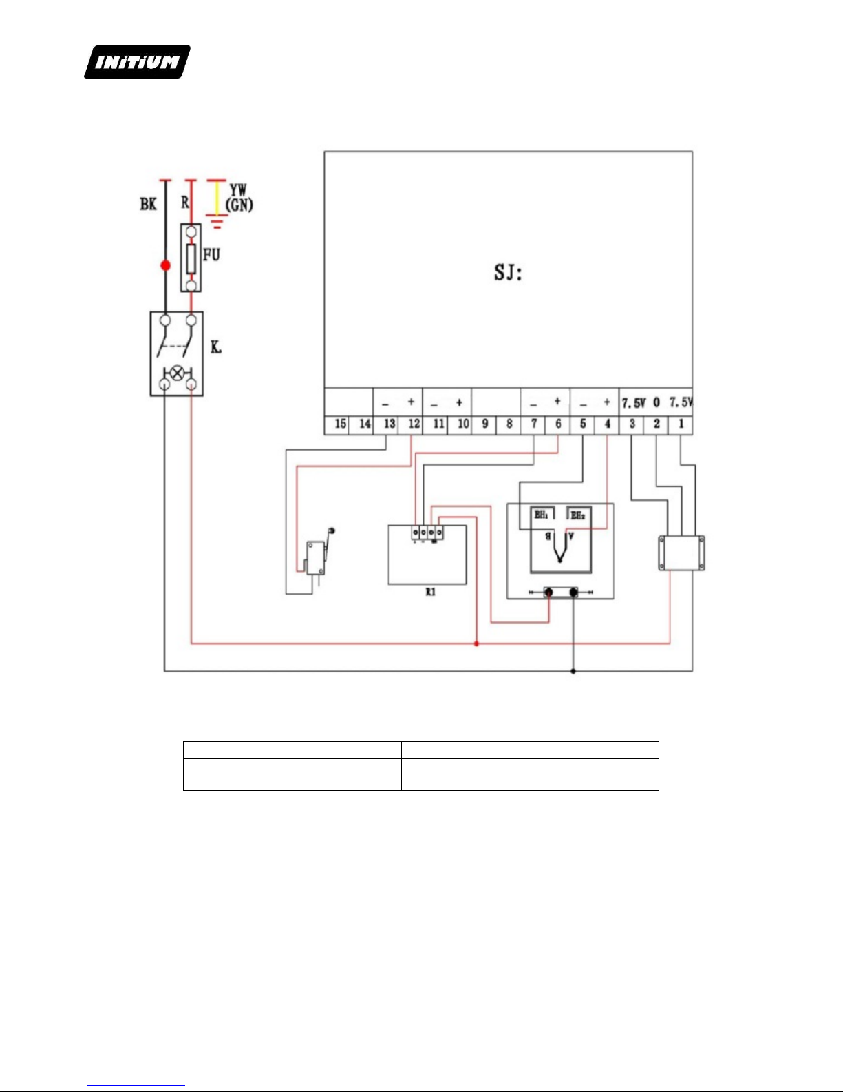
K0
Power Switch
EH1EH2
Heating Pipe
SJ
Digital Controller
T
Transformer
FU
Fuse
R1
Relay
Page 11
V0414
Page 11
VII. MAINTENANCE
USE BY QUALIFIED STAFF ONLY
ANY SERVICING INTERVENTION MUST BE DONE WHEN THE MACHINE IS OFF AND LOCKED
(ELECTRIC AND PNEUMATIC ENERGIES UNPLUGGED)
1. SERVICING
Heat transfer press INITIUM ® require little maintenance. To ensure proper operation, follow the
preventive guidelines listed below.
Do not heat objects that could damage or even cut the silicon rubber or damaging the Teflon surface
DAILY :
CHECK that the heating element is clean.
EVERY 3 MONTHS :
Put a few drops of oil onto the various pivot pins and the pressure
adjusting screw
2. QUICK REPAIR ADVICES
SYMPTOMS
REPAIRS
No action after turn on the machine
1). Check the plug whether it connects well or whether it is broken.
2). Check the power switch or digital controller whether it is broken.
3). Check the fuse whether it has been burnt out.
4). Indicating light is on, but no display on screen, check the 5 cable of
Railway transformer. If it’s loosening, showing the problem is poor
connection. If they connects well, showing that the Transformer is faulty
The display screen is working well, but
no temperature increasing on the
heating element.
1). Check whether the thermocouple of the heating element touches well.
If the thermocouple is loose, the display will show 255℃. and machine
keeps beeping.
2). Check if the indicating light of solid-state relay is on, if not, check if
the relay or digital controller is broken.
3). If you already changed the new solid-state relay but the heating
element still can’t heating up, check if the heating element is faulty or the
heating element power cable is loose, need to change by new mug
heater.
The display screen show 255℃ once
you power on
1). Check whether the thermocouple is loose or not.
2). If the thermocouple touches is not in loose state, but still show
255℃, then it is faulty.
The machine is heating during
0~180℃, but display number jumps to
above 200℃ or 300℃ suddenly, or the
numbers on display jumps irregularly
1). Check whether the thermocouple of the heating element touches well.
2). If the thermocouple is good, It shows that the program of digital
controller is broken, which namely IC or is broken, need to change by
new controller.
The temperature is out of control: Set
180℃,but the actual temperature is
above 200℃
1). It means the solid-state relay is broken, out of control, need to
change the relay.
2). Or the digital controller is faulty and it keeps conveying electric to
relay, need to change controller.
The setting temp and time becomes
abnormal after exchange the heating
element
1). Please reset the temp and time according the operation process
manual
Other notice
1). In order to prolong the machine service life, please add the
lubrication oil regularly on the joints.
2). In order to keep the heating element good transfer effect, please
protect it carefully whenever you are using or not.
3). Please keep the machine in dry place.
4). If you are not able to solve the electrical parts problem, please
contact the supplier
Page 12
V0414
Page 12
3. TROUBLE SHOOTING FOR TRANSFER PRINT QUALITY
If the print color is pale: the temperature is too low / the pressure is not correct / or not pressed long enough.
If the print color is too brown or the transfer paper is almost burnt: reduce the setting temperature.
If the print is blurring: too much transfer time causes proliferation.
If print color is different/ partial transfer effect is not good enough: the pressure is not enough / or not pressed
long enough / or poor quality transfer paper.
If transfer paper stick to the object after transfer: the temperature is too high/ or poor quality printing ink.
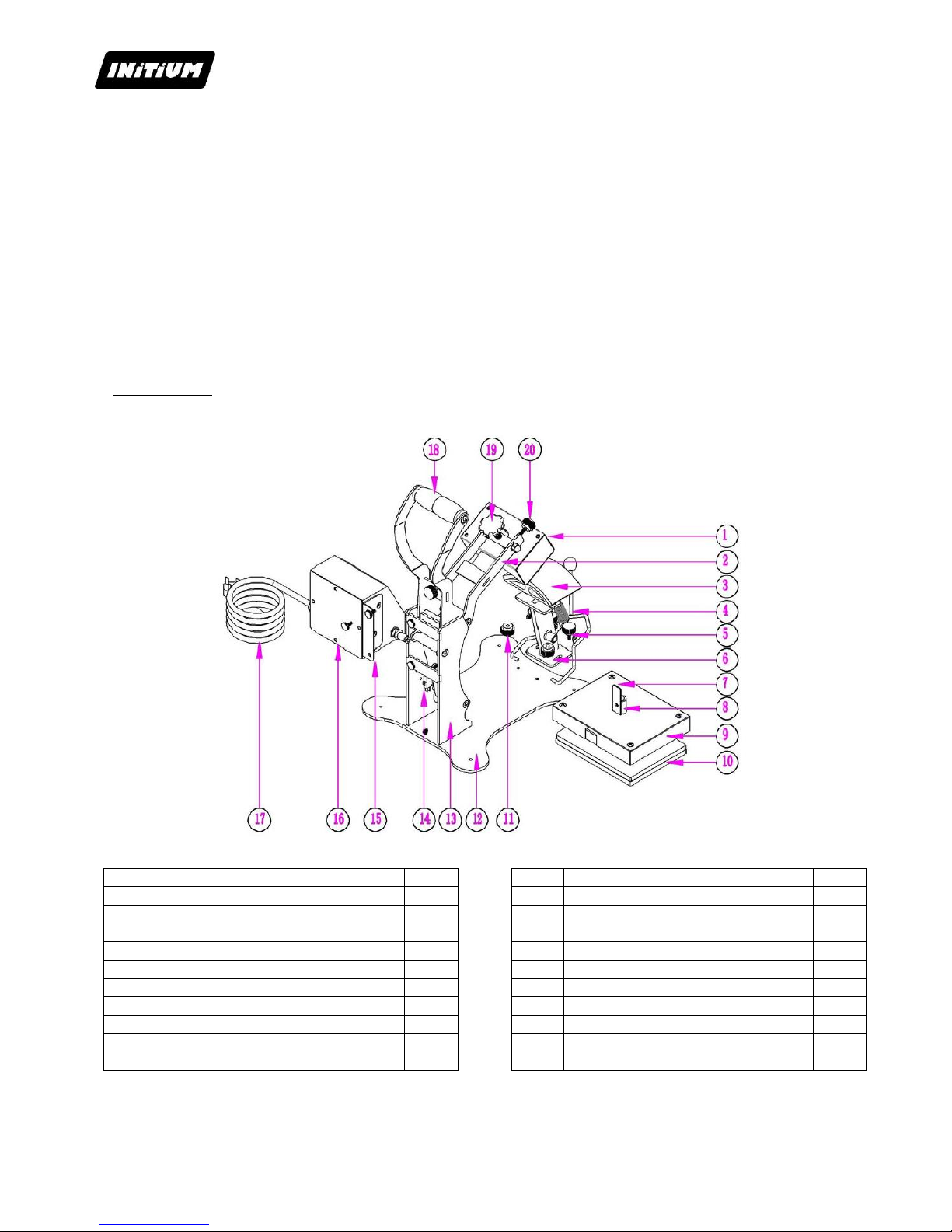
4. EXPLOSION VIEW
For any order : specify designation and quantity
Item
Parts Name
Qty
1
Cap Heater
1 pc
2
Handle Shaft
1 pc
3
Cap Under Plate
1 pc
4
Cap Presser
1 pc
5
Screw
2 pc
6
Supporting Holder
1 pc
7
Anti-swing Part
1 pc
8
Adapter
1 pc
9
Flat Heat Platen
1 pc
10
Flat Under Plate
1 pc
Item
Parts Name
Qty
11
Screw
2 pc
12
Machine Base
1 pc
13
Supporting Plate
2 pc
14
Limit Switch
1 pc
15
Electrical Parts Bracket
1 pc
16
Electrical Case
1 pc
17
Power Cord
1 pc
18
Handle Bar Grip
1 pc
19
Pressure Adjusting Screw
1 pc
20
Screw
1 pc
 Loading...