

Page 1
English version
INSTRUCTION MANUAL
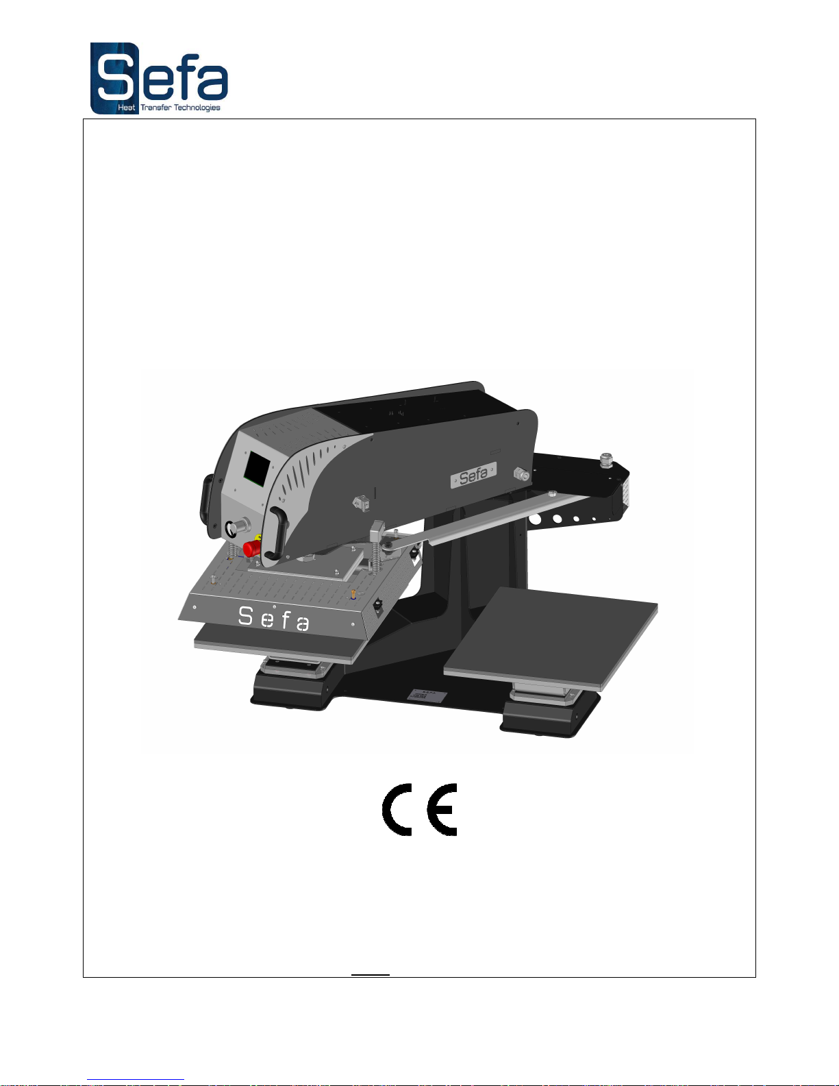
DUPLEX PRO
S.E.F.A
®
Z.I PASTABRAC
11260 ESPERAZA
FRANCE
Tel: 33 (0)4.68.74.05.89 - Fax: 33.(0)4.68.74.24.08
E Mail: [email protected]
Page 2

English version
V0516
Page no. 1
WARRANTY TERMS
The warranty period shall come into effect on the day on which the equipment is brought into service at the
user's premises, as attested on the returned warranty certificate and the delivery note, and shall run for
two years, based on a standard equipment operating schedule of 8 hours per day, i.e. 3,000 hours.
The warranty is strictly limited to our equipment, and covers faulty materials and workmanship, which the
purchaser shall be required to substantiate.
Our liability shall be limited to making good or replacing free of charge parts that are acknowledged by us to
be defective, and no claims for damages for any reason may be made against us.
Parts replaced under warranty shall:
remain our property
be invoiced on consignment
A credit note will be issued upon return of the faulty parts.
Returns must be made NO LATER THAN ONE MONTH after the work is performed under warranty.
THIS WARRANTY DOES NOT COVER:
Commercially sourced wearing parts, material and equipment such as:
- Fuses, bulbs, seals, hoses, nozzles, filters, etc.
- Material and equipment not manufactured wholly by us, which are covered by the warranty of the
manufacturer thereof.
THIS WARRANTY DOES NOT EXTEND TO:
Replacements or repairs arising from fair wear and tear of the appliances or machines, damage or accidents
arising from negligence, lack of supervision or maintenance, improper use or alterations made without our
written consent.
Defects arising from material provided by the purchaser or mandatory design requirements issued by the
purchaser.
Repairs made necessary by damage or accidents arising during carriage.
Normal maintenance and adjustment procedures required during use of the machine, as set out in the
maintenance instructions, such as:
- adjustment of intermediate components
- tightening of pipes, hoses, etc.
Any traces of detergent oil in the air system of pneumatic machines shall invalidate the
aforementioned warranty terms.
Quote the machine reference and serial number when making technical enquiries or
ordering spare parts.
Page 3

English version
V0516
Page no. 2
INDEX
WARRANTY TERMS ................................................................................................................................................................. 1
INDEX .......................................................................................................................................................................................... 2
TECHNICAL DATA .................................................................................................................................................................... 3
SETTING UP THE MACHINE .................................................................................................................................................. 3
OVERVIEW ................................................................................................................................................................................. 4
OPERATION ............................................................................................................................................................................... 4
1.
SAFETY .................................................................................................................................................................................. 5
a) International symbols ......................................................................................................................................................... 5
b) Important safety precautions.............................................................................................................................................. 5
c) Safety features .................................................................................................................................................................... 5
Safety system checks ............................................................................................................................................................... 6
After an emergency stop ......................................................................................................................................................... 6
Instructions and manuals ....................................................................................................................................................... 6
2. SWITCHING
ON ................................................................................................................................................................... 7
3. CONTROL
PANEL ................................................................................................................................................................. 7
4.
SETTINGS ............................................................................................................................................................................. 8
a) Temperature ....................................................................................................................................................................... 8
b) Timer .................................................................................................................................................................................. 8
c) Pressure ............................................................................................................................................................................. 8
d) Swing-away speed .............................................................................................................................................................. 8
5 .OPERATING
CYCLE .............................................................................................................................................................. 8
6. ELECTRONIC BOARD
SETTINGS ........................................................................................................................................ 9
a) Presets ................................................................................................................................................................................ 9
b) Settings menus .................................................................................................................................................................... 9
c) Sleep mode ....................................................................................................................................................................... 10
d) Machine settings .............................................................................................................................................................. 10
e) User comfort settings ....................................................................................................................................................... 11
f) Energy saving mode .......................................................................................................................................................... 11
7. FULL-AUTO MODE
(OPTIONAL) ....................................................................................................................................... 12
a) Cycle options: "foot pedal", "single workstation" and "full auto" .................................................................................. 12
b) Selecting a work mode: .................................................................................................................................................... 12
c) Setting the "post-press timer" (in automatic mode only): ................................................................................................ 12
PARTS LAYOUT ....................................................................................................................................................................... 13
WIRING AND PNEUMATIC DIAGRAM ............................................................................................................................ 14
SERVICING ............................................................................................................................................................................... 16
1. REPLACING WORN
PARTS ................................................................................................................................................ 16
a) Silicone foam pads ........................................................................................................................................................... 16
b) Other parts ....................................................................................................................................................................... 16
2. M
AINTENANCE
........................................................................................................................................................................ 16
3. ELECTRONIC BOARD
MESSAGES..................................................................................................................................... 17
WEAR PARTS ........................................................................................................................................................................... 17
TROUBLESHOOTING TIPS .................................................................................................................................................. 18
MAINTENANCE LOG .............................................................................................................................................................. 19
Page 4
English version
V0516
Page no. 3
TECHNICAL DATA
Non-contractual document: we reserve the right to alter our product specifications in line with advances in technology.
SETTING UP THE MACHINE
TO BE PERFORMED BY QUALIFIED PERSONNEL
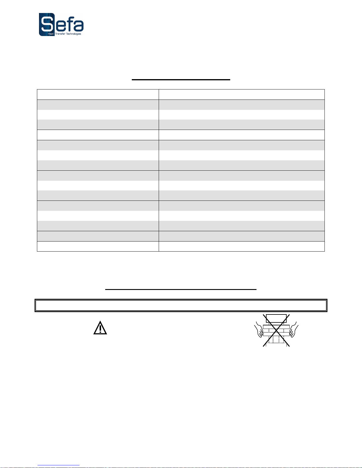
Do not hold the machine by the platens!
Remove the machine from its packaging. The machine is secured to a pallet.
Place the machine on a stable, level table using the carry bars.
Secure the machine to the table.
Place the foot pedal on the floor.
Plug in the press using the plug provided (230 Volt + Earth / 50 or 60 Hz).
Connect the press to your compressed air supply (min. 3.5 bar, max. 10 bar).
Weight in working order
150 kg
Height
713 mm
Depth 1005 mm
Width 1071 mm
Platen size 400 x 500 mm
Power supply
220/240 V Single phase + Earth 50/60 Hz
Power consumption
3200 W
Amp rating
14A
Electronic temperature controller
Accuracy
+/- 1%
Setting range
0 to 255 °C
Electronic timer
Accuracy
+/- 1%
Setting range
0 s to 11 min
Noise level Below 70 dB (A)
Maximum pressing force
925 daN
Page 5
English version
V0516
Page no. 4
OVERVIEW
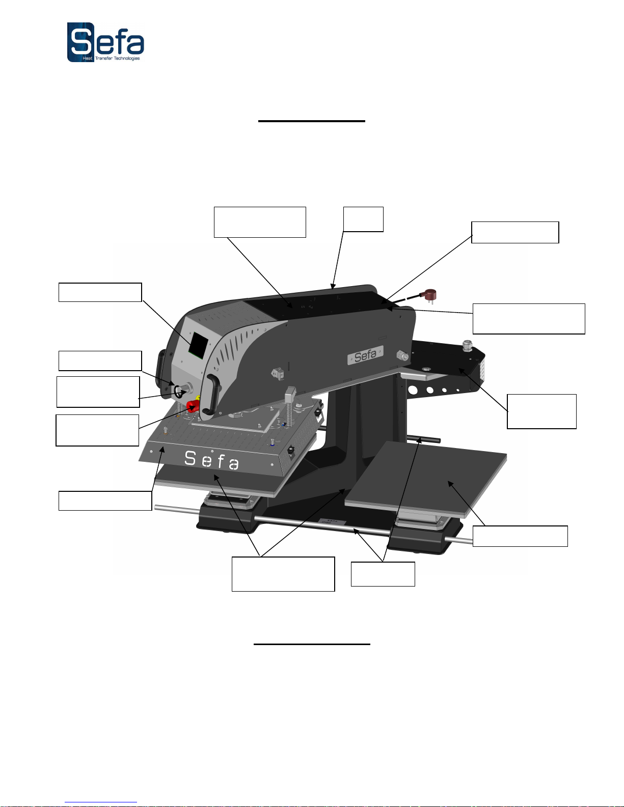
This heat press has been designed to operate at high output without risk to operator safety in accordance with
article L 233-5 of the French labour code.
It has been designed for use by a single operator positioned in front of the machine.
OPERATION
Please read the Operating Manual carefully before operating the press.
The press should be operated by a qualified person who is aware of the potential dangers arising from improper
use of the equipment.
The factory-installed pneumatic, electrical and mechanical settings programmed by our technicians and the safety
features must not be altered under any circumstances. SEFA accepts no liability for problems that may be caused
by the machine if such alterations are made.
Heat platen
Emergency
stop
Silicone foam pad
Detachable lower
platens
Filter
Touch screen
Cover +
electronic board
Plug + fuse
Air inlet connection
Pressure gauge
Auto-swing
cylinder
Pressure
adjustment dial
Carry bars
Page 6
English version
V0516
Page no. 5
1. SAFETY
THIS MACHINE IS DESIGNED FOR USE BY A SINGLE OPERATOR
FOR USE BY QUALIFIED PERSONNEL
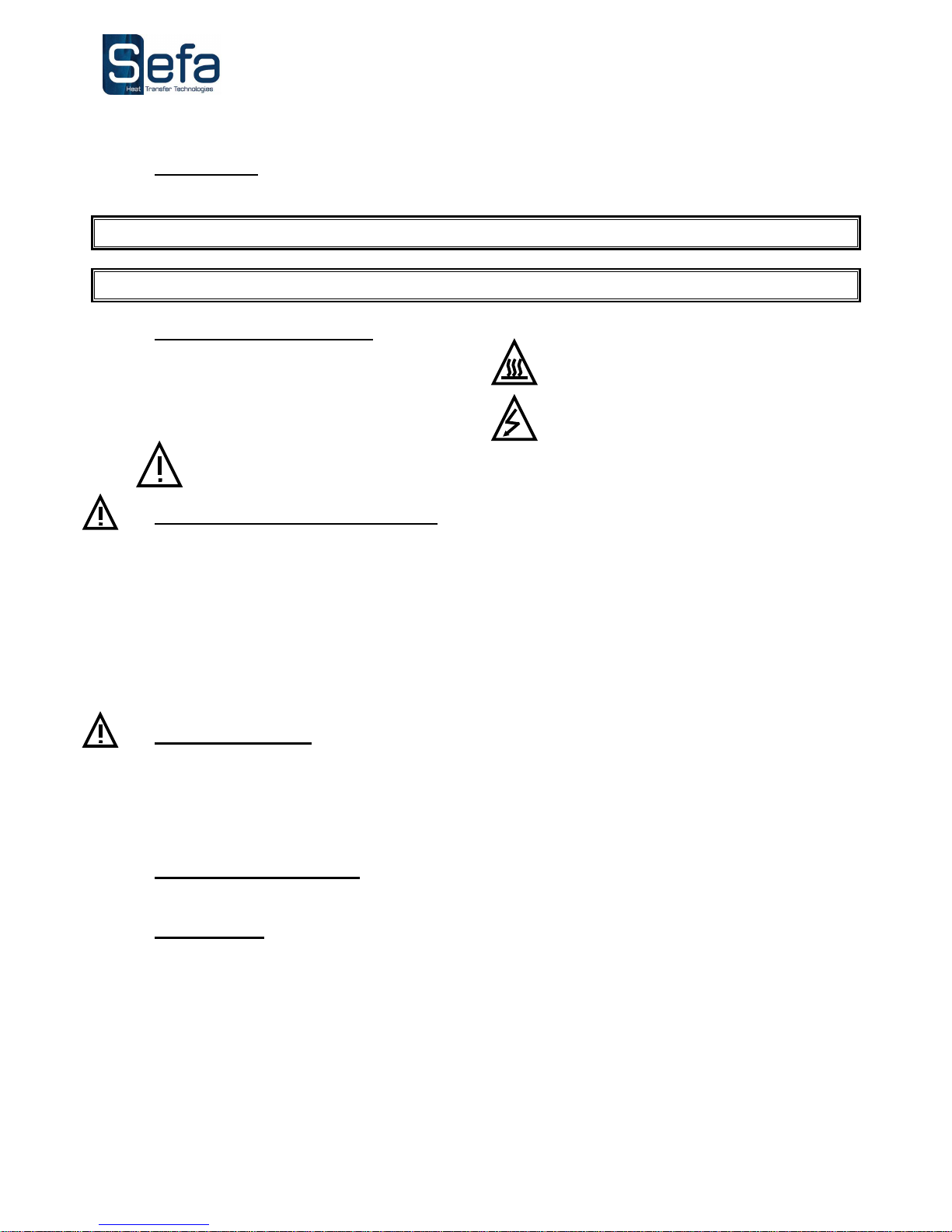
a) International symbols
b) Important safety precautions
Personal protective equipment should be worn (e.g. safety gloves and glasses).
Do not touch hot parts of the machine during use.
Do not place hands between the platens when the machine is switched on.
Make sure the operator is not exposed to risks of burns, electrocution or other hazards when handling the
machine.
Check the machine each day before use.
Make sure there is nobody in the vicinity of the machine before starting work.
If the machine malfunctions, cut the power supply and look for the cause of the problem (see the Servicing
section).
c) Safety features
No changes must be made to the safety covers and safety systems.
They must be refitted if they are removed for servicing work.
They must be held securely in place and kept in good condition during normal use.
DUPLEX PRO presses are fitted with safety systems to protect the operator from pinch-point hazards.
The main safety components are:
Emergency stop button
Front-mounted button that switches the machine off when pressed.
Safety cover
Two contact switches are located on top of the upper heat platen.
This system helps safeguard the operator against pinch points and crushing hazards.
If the system detects an obstacle, it raises the heat platen, immediately shuts off the swing function and puts the
press into safe mode.
To restore the machine to operating mode, press the RESET button, position the swing arm over one of the lower
platens and depress the foot pedal.
O
I
OFF
ON
DANGER, WARNING
HOT SURFACE
ELECTROCUTION HAZARD
Page 7

English version
V0516
Page no. 6
Safety system checks
Test the emergency shut-off and the safety cover daily.
After an emergency stop
Make sure there are no other unresolved problems preventing use before restoring the machine to normal
operating mode.
Turn the red button to release the emergency stop. The machine will be reset automatically.
Instructions and manuals
Technical parts documents are supplied with the machine. Please read them before starting to use your SEFA
machine.
Page 8
English version
V0516
Page no. 7
2. SWITCHING ON
Press the main switch at the back of the machine to turn the power on.
Check that the display panel comes on. The screen will show a welcome message, followed by the factory
settings.
Adjust the temperature (to suit the type of transfer).
Adjust the press time (to suit the type of transfer).
Adjust the pressure using the dial (to suit the type of transfer) and check the pressure gauge reading.
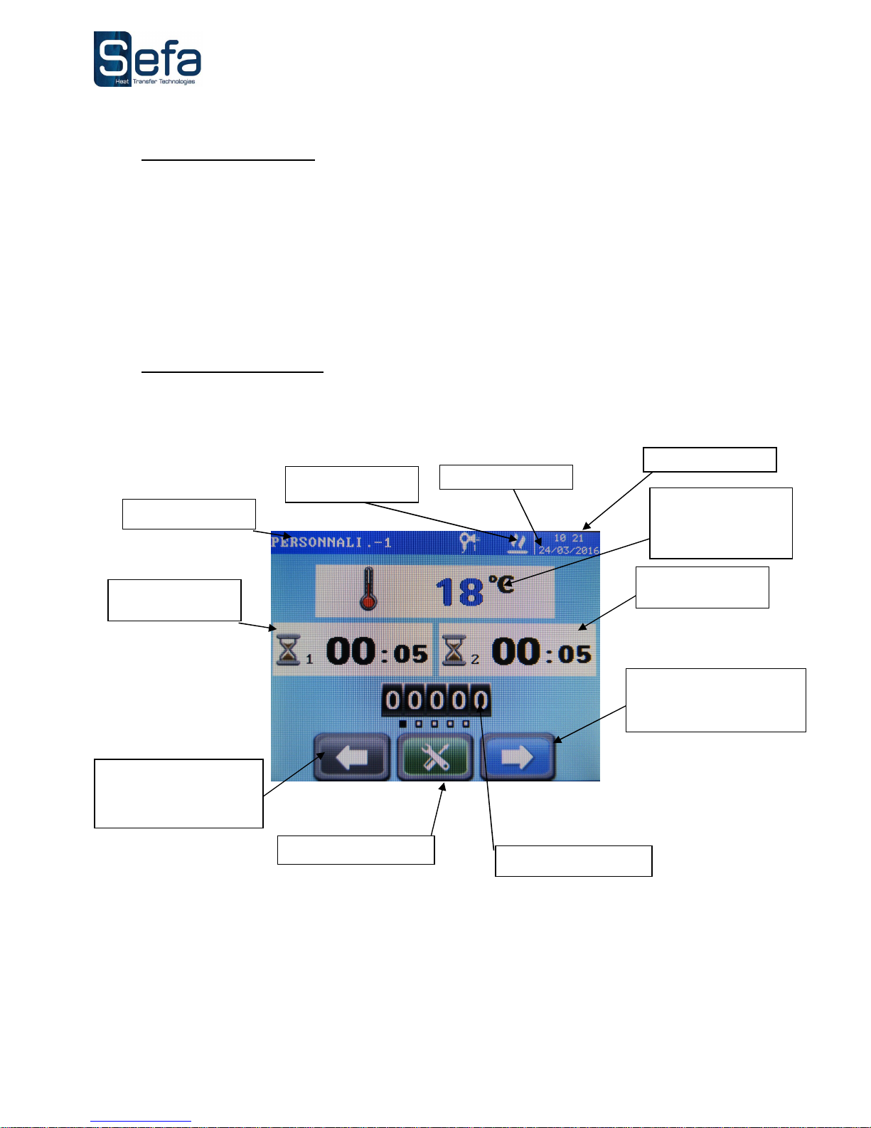
3. CONTROL PANEL
Current temperature
reading and
temperature
adjustment
field
Heating indicator
Right platen timer
Date
Settings menu key
Increment-up, open next
menu, browse presetting
sub-menus
Increment-down, open
previous menu, browse
presetting sub-menus
Time
Left platen timer
Resettable counter
Presets
Page 9
English version
V0516
Page no. 8
4. SETTINGS
a) Temperature
Press the temperature field on the touch screen
Press and hold the ”-” or ”+” key to decrease or increase the setting respectively.
Press the "welcome" key to confirm and accept.
You can also select presets using the arrow keys.
b) Timer
Press one of the two timer fields on the touch screen (each side, left and right, has a different setting)
Press and hold the ”-” or ”+” key to decrease or increase the setting respectively.
Press the "welcome" key to confirm and accept.
You can also select presets using the arrow keys.
c) Pressure
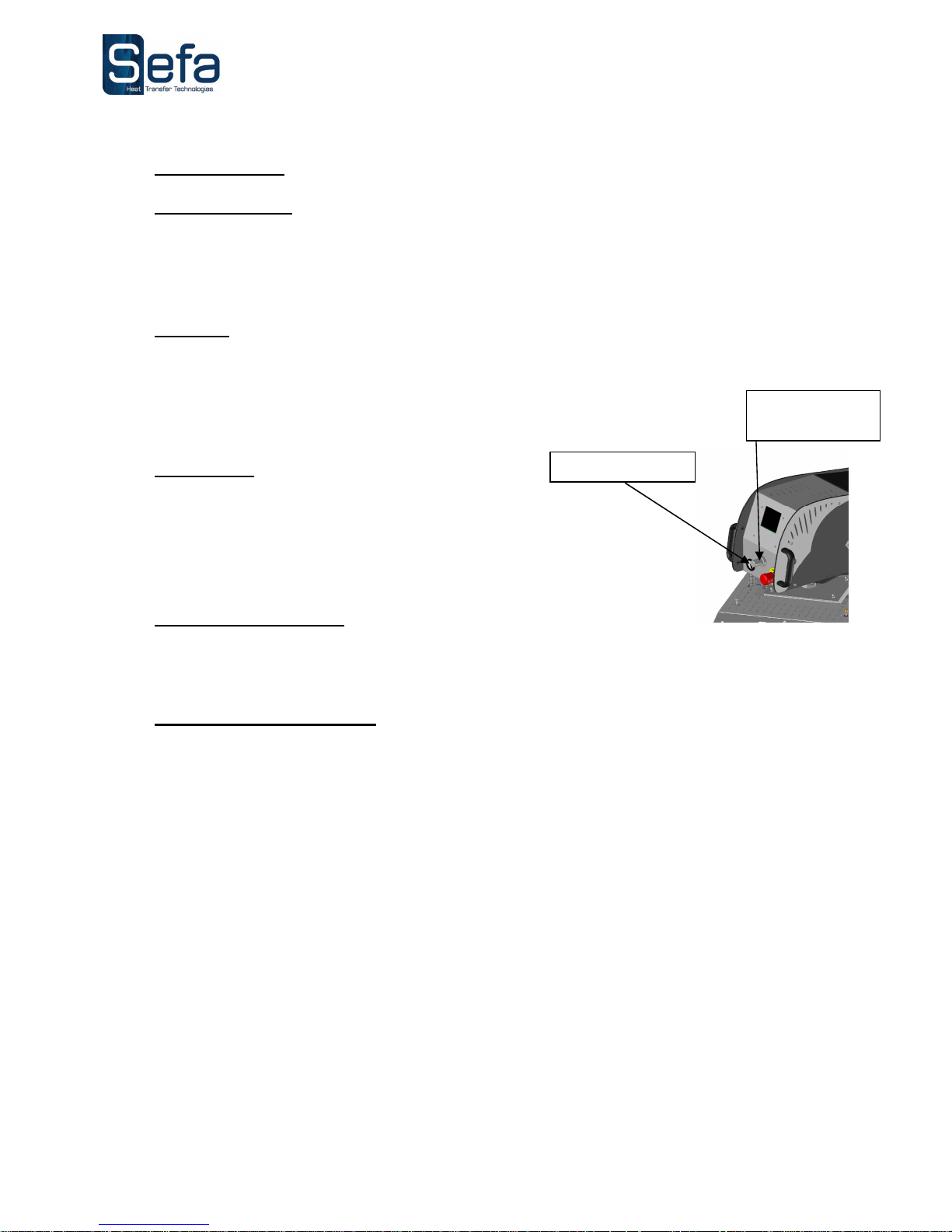
Use the front-mounted pressure adjustment dial.
The pressure is shown on the pressure gauge indicator.
Pull and then turn the adjustment dial:
clockwise to increase the pressure,
anticlockwise to reduce the pressure.
• Push the dial back in to save the new setting.
d) Swing-away speed
Contact your official SEFA stockist to adjust this setting.
5 .OPERATING CYCLE
Move the swing arm away to the opposite side from the platen you want to work on.
Depress the foot pedal to confirm your selection.
Place the work item on the lower platen.
Position the transfer sheet correctly.
Depress the cycle start foot pedal.
The swing arm will move into place over the platen, the heat platen will lower and the press timer will
start.
Use this time to prepare the next work item and transfer sheet on the second workstation.
The heat platen will lift open when the timer has finished.
Depress the foot pedal if the machine is not in “FULL AUTO” mode.
If the machine is operating in Full Auto mode, the platen will swing away automatically after it has lifted clear and
the post-press timer has finished its countdown.
Remove the work item from the first workstation and get the next one ready.
Repeat from step three above.
Depressing the foot pedal during a cycle will stop the cycle and move the swing arm to the other side.
Pressing the stop button during a cycle will stop the cycle.
Pressure
adjustment dial
Pressure gauge
Page 10
English version
V0516
Page no. 9
6. ELECTRONIC BOARD SETTINGS
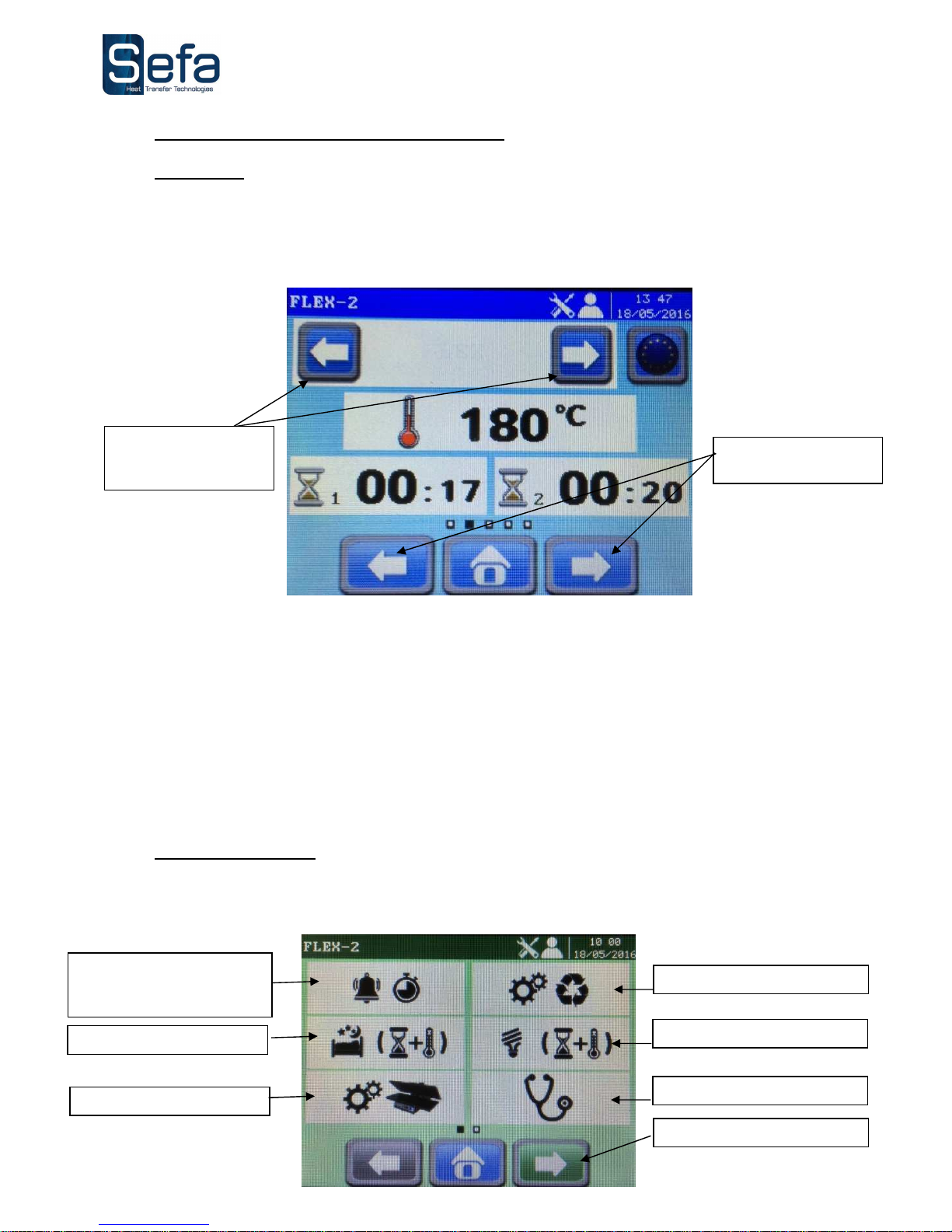
a) Presets
This menu contains nine pre-saved operating programs; up to five presets can be assigned to each program by
entering the required setpoints.
The operating programs must be suited to the processes you use. The temperature adjustment system is finetuned for each program.
Available programs:
Customised: the system applies the user-defined settings keyed in at the control panel
Flex: for placing flex and flock
DTG 1: for drying pre-treated materials
DTG 2: for pressing pre-treated materials
SUBLI T: for sublimation printing on textiles
SUBLI R: for sublimation printing on rigid materials
SCREEN: for placing screen transfers
LASER: for placing laser transfers
QUICKFLEX: for placing flex in under 5 seconds
b) Settings menus
Press the green key in the centre of the screen to open the settings.
Click to open the required menu.
Press the arrow in the bottom centre of the screen to exit.
Browse between
programs
Browse between
program presets
End-of-cycle beeper time
setting
Machine settings
Energy saving mode
User comfort settings
Sleep mode
Diagnostic mode
To next screen
Page 11
English version
V0516
Page no. 10
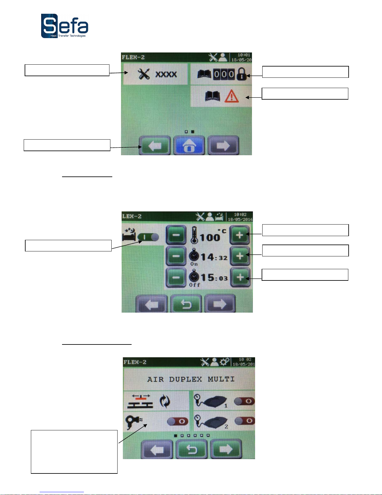
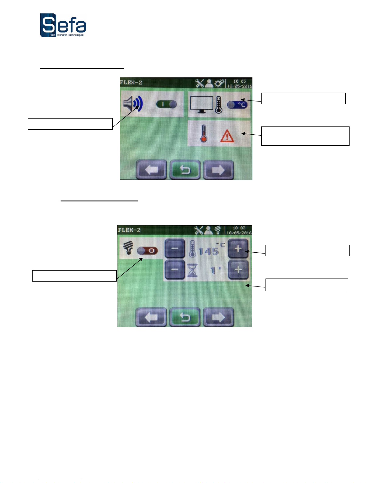
c) Sleep mode
Sleep mode keeps the machine temperature at a certain level for a certain length of time
d) Machine settings
Internal menu code
Error log (last 10 errors)
Counters
To previous screen
On/off
Temperature in sleep mode
Start of sleep mode
End of sleep mode
Enable drying mode
The drying time is set at the
control panel with the
pressing time setpoint
Page 12
English version
V0516
Page no. 11
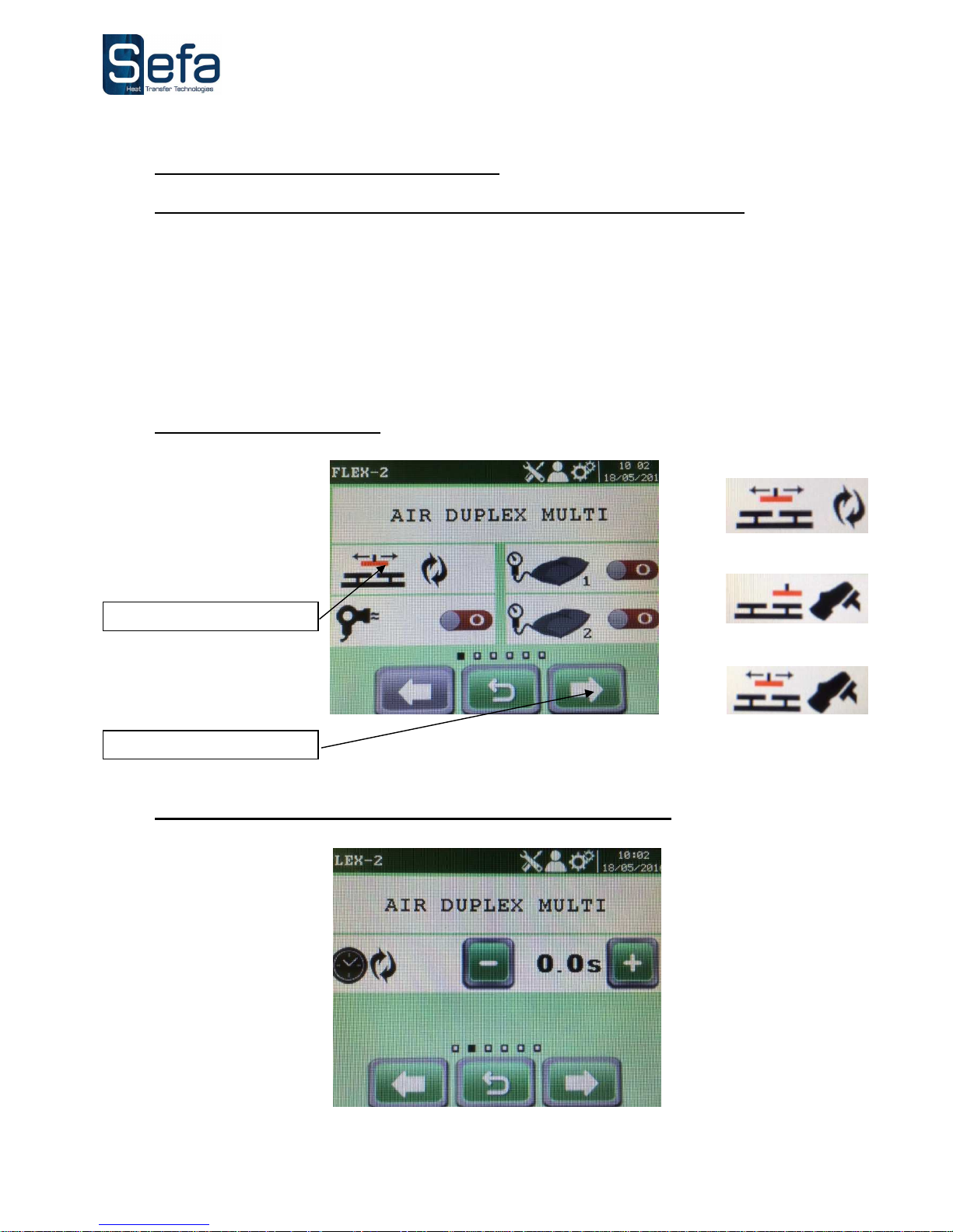
e) User comfort settings
f) Energy saving mode
Energy saving mode reduces the machine temperature to the set temperature when the defined idle time has
elapsed.
Enable/disable buzzer
°C / °F
Machine operating
temperature range
On/off
Temperature
Time
Page 13
English version
V0516
Page no. 12
7. FULL-AUTO MODE (OPTIONAL)
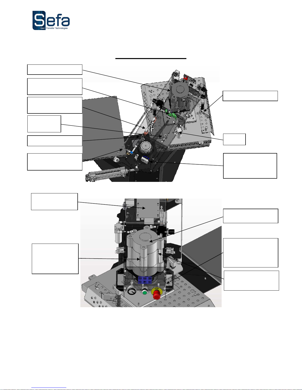
a) Cycle options: "foot pedal", "single workstation" and "full auto"
DUPLEX PRO has 3 cycle options:
Foot-pedal mode: depressing the foot pedal causes the arm to move to the other platen and press.
Single-station mode: depressing the foot pedal causes the arm to move to the other platen, press and then
return to the original platen.
Automatic mode: depressing the foot pedal causes the arm to move to the other platen and press. When
the "post-press timer" has finished, the arm automatically returns to the other platen and presses again. This is
repeated until the operator stops the automatic cycle by pressing the STOP icon or depressing the foot pedal.
b) Selecting a work mode:
c) Setting the "post-press timer" (in automatic mode only):
Work mode selection
Full-auto mode
Single-station mode
Semi-automatic
foot-pedal mode
To post-press timer setting
Page 14
English version
V0516
Page no. 13
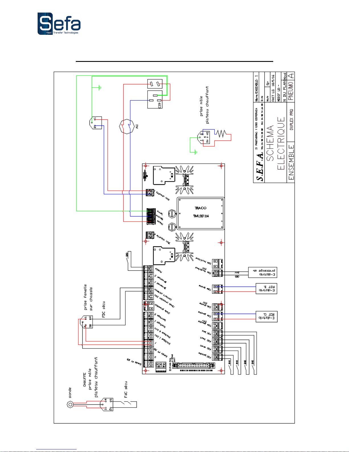
PARTS LAYOUT
NB: the electronic board is underneath the housing cover (not shown)
Filter
Press cylinder
Cylinder
stop
Air supply
connection
Safety sensors
Swing function
solenoid
Swing controller
Magnetic passthrough sensor
(LOWER travel
limit)
Press cylinder
NB: the front panel
pivots away
leaving the two
bottom screws
Control board
Power inlet +
fuses
Press function
solenoid
Magnetic sensor
UPPER travel limit
Page 15
English version
V0516
Page no. 14
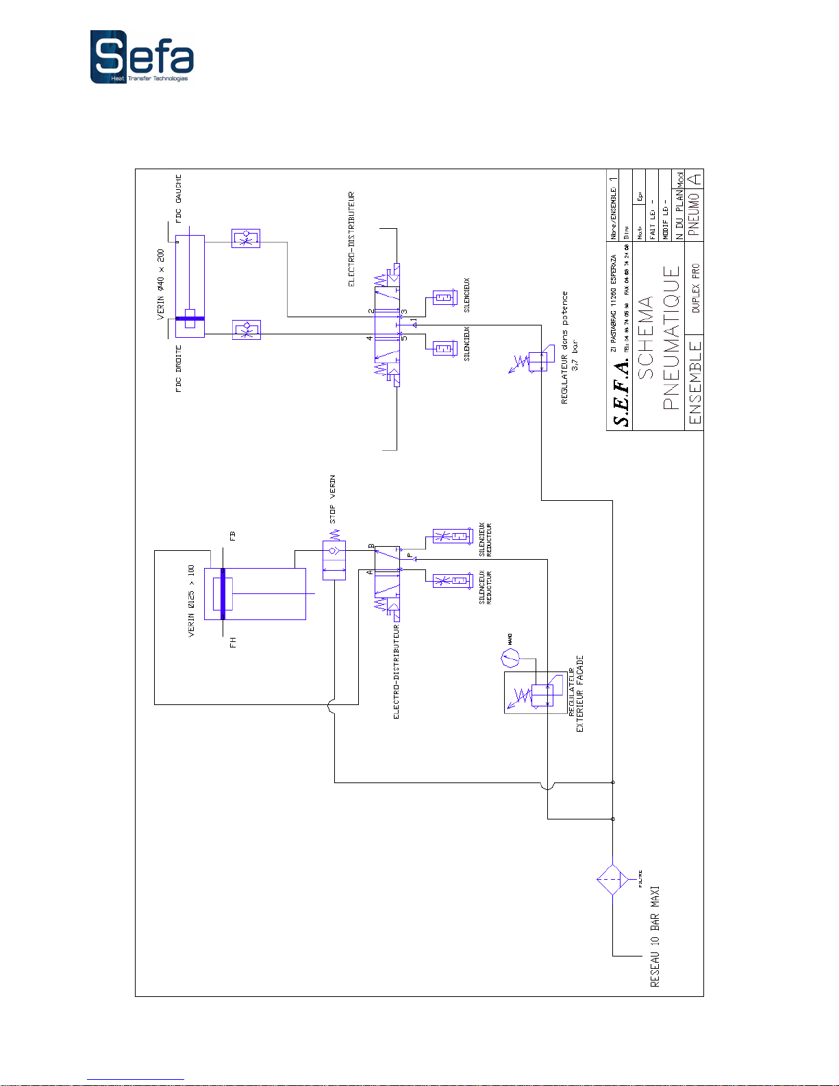
WIRING AND PNEUMATIC DIAGRAM
Page 16
English version
V0516
Page no. 15
Page 17

English version
V0516
Page no. 16
SERVICING
TO BE PERFORMED BY QUALIFIED PERSONNEL
THE MACHINE MUST BE SWITCHED OFF AND LOCKED AND TAGGED
PRIOR TO SERVICING
(ELECTRIC AND PNEUMATIC POWER SOURCES DISCONNECTED)
The following tools should be available at hand:
Phillips and flat-blade screwdrivers
Set of open-ended spanners and box spanners
Set of Allen keys
Multimeter
1. REPLACING WORN PARTS
a) Silicone foam pads
Check that the platen is cold.
Make sure the surface of the platen is clean.
The surface can be cleaned using a mild solvent such as isopropyl alcohol. Suitable personal protective equipment
must be worn.
Use RTV-1 glue to stick the foam pad to the aluminium platen (NB: read the instructions for use on the packet).
The pad and the platen must be clean and dry before they are stuck together.
Apply a thin layer of glue evenly over the platen and then stick the pad immediately into place, making sure there
are no air bubbles trapped between the platen and the pad (NB: a notched adhesive comb of the type used for
floor tiling would be suitable).
Leave to set overnight at room temperature with a slight pressure applied and the platen cold.
b) Other parts
Contact your stockist to determine whether they need to be renewed or repaired.
2. Maintenance
SEFA heat presses are practically maintenance-free. Follow the preventive maintenance instructions below to
ensure trouble-free operation:
Do not heat items that could perish or score the silicone pad or damage the heat platen’s teflon coating.
Clean the machine at regular intervals, with the platen cold, using a clean cloth and isopropyl alcohol (NB:
isopropyl alcohol is flammable - use with care and keep away from sources of heat) and wearing suitable personal
protective equipment.
Keep the heat platen in the raised position when it is hot but not in use.
DAILY CARE:
Clean the foam pad and the platen’s coating (when cold) with a dry cloth or a dry cloth and grease
remover.
Inspect the air inlet filter on the left side of the swing arm; drain the filter if it is heavily condensated.
MONTHLY CARE:
Check that the hinged joints are lubricated.
According to use:
Replace the foam pad every 6 months.
Page 18
English version
V0516
Page no. 17
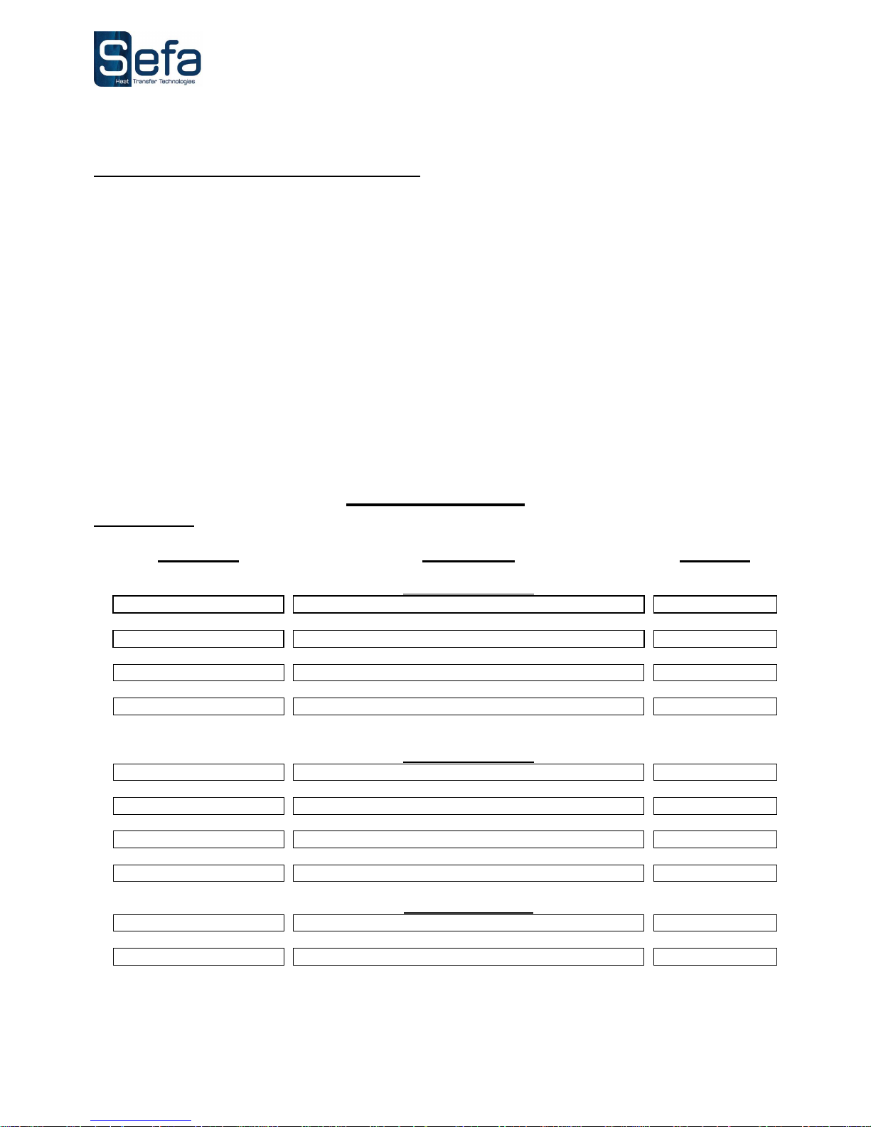
3. ELECTRONIC BOARD MESSAGES
Alert 1: PT100 unplugged
Alert 2: Platen safety device
Alert 3: Triac 1 short-circuited
Alert 4: Triac 1 control out of order
Alert 5: Triac 1 relay short-circuited
Alert 7: Clock battery
Alert 8: Cylinder PR245 lift action
Alert 9: Cylinder PR245 lowering action
Alert 11: Machine cylinder manual lift
Alert 12: Heat platen timed out
Alert 14: PT100 > Max. temperature drop setpoint
Alert 15: PT100 > Max. permitted temperature setpoint
Alert 16: Triac 2 control out of order
Alert 17: Triac 2 relay short-circuited
Alert 18: RH travel limit not reached
Alert 19: LH travel limit not reached
Alert 20: Variance between lower travel limit and upper travel limit
Alert 21: Variance between RH travel limit and LH travel limit
WEAR PARTS
When ordering:
always quote the description, reference and quantity
R
efe
rence
Description
Quantit
y
ELECTRICAL PARTS
AFF-EL3’’5
MMI TOUCH SCREEN
1
CAR-EL C
POWER BOARD
1
SON-PT100
TEMPERATURE PROBE
1
RES-500x400-3200W
MICA HEATING ELEMENT 400x500 3200 W
1
PNEUMATIC PARTS
VER-SM25
CYLINDER Ø125 C100
1
VER-SM23
CYLINDER Ø40 C200
1
FIL-013
FILTER
1
ELE-SM8
SOLENOID CONTROL VALVE 24V
1
PRESS COVERINGS
MOU-540
FOAM 9.53mm 400X500
2
TOI-4050
TEFLON SHEET
1
Page 19
English version
V0516
Page no. 18
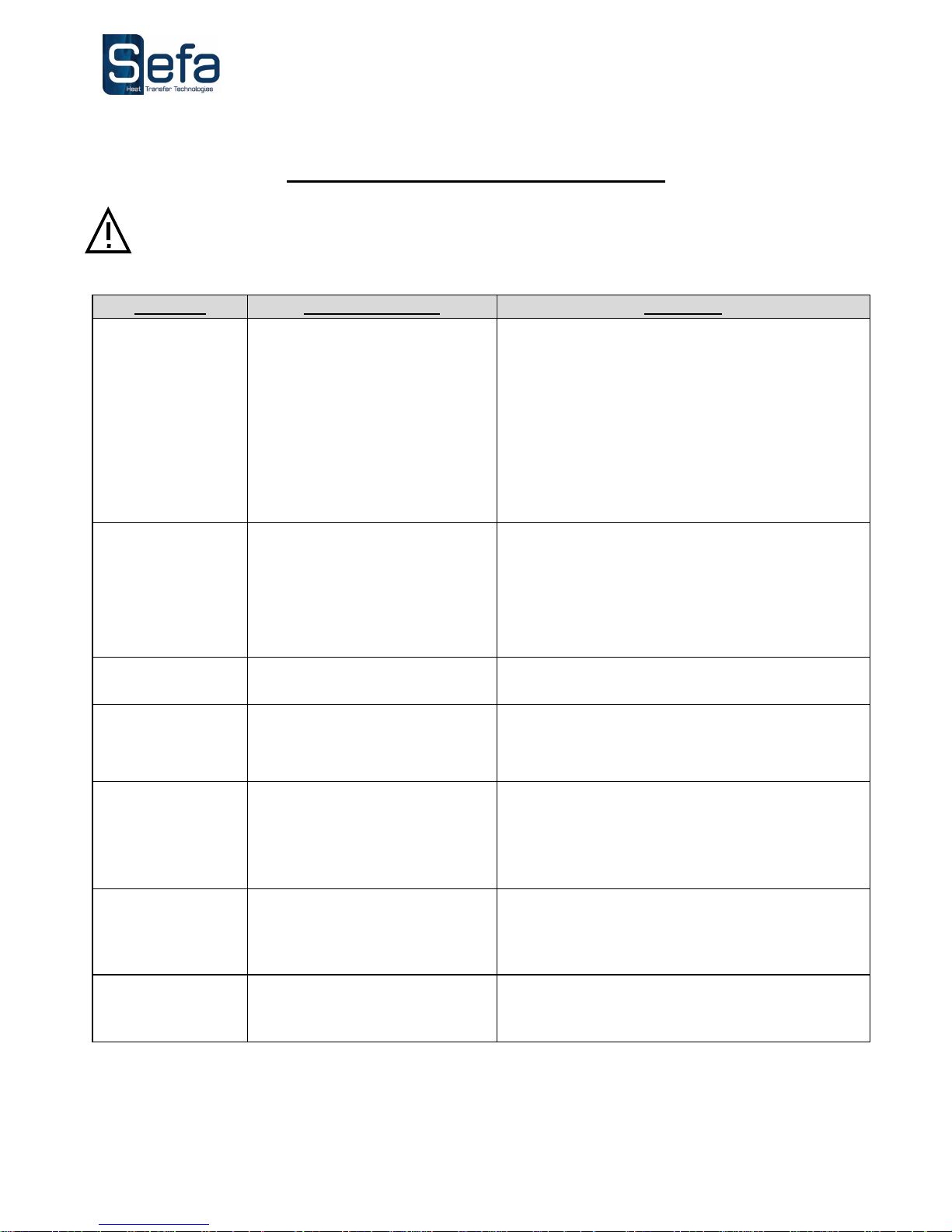
TROUBLESHOOTING TIPS
The machine must be switched off and locked and tagged prior to any service repair work (electric and
pneumatic power switched off).
The heat platen can cause burns. Check that the platen temperature reading on the display panel is below
25° C before handling.
PROBLEM POSSIBLE CAUSES SOLUTION
The machine does not
switch on
The plug is not connected
The switch has not been
pressed
The emergency stop has
been pressed
Faulty display panel
Check the mains electricity and that the
machine is plugged in.
Press the main On/Off switch to 1.
Turn the red button to disengage the
emergency stop
Check whether the ribbon cable is connected
properly; otherwise, the display is out of order
The platen does not
heat up
Faulty heating element
Problem with the electronic
board
Temperature setting too low
Check the connections and the condition of the
wires.
Contact your stockist to have the platen removed
Check the on-screen messages and contact
your stockist
See section V about changing this setting
The platen overheats
Problem with the probe or
the electronic board
Check the on-screen messages and refer to the
board user manual. Contact your stockist.
The timer does not
count down
Disabled or faulty cylinder-
mounted sensor
Problem with the electronic
board
Check the connections. Replace if necessary.
Check the on-screen messages and refer to the
board user manual.
The platen does not
lower
Leaking cylinder
Faulty solenoid control valve
Compressed air pressure too
low
Check the seals and all the connections.
Contact your stockist.
Check the valve couplings. Contact your stockist
about a possible replacement.
Check that the supply pressure is > 3 bar.
The platen does not
lift up
Faulty solenoid control valve
Leaking cylinder
Check the valve couplings. Contact your stockist
about a possible replacement.
Check the seals and all the connections.
Contact your stockist.
The platen stays
down after pressing
Timer not counting down See above.
Page 20

English version
V0516
Page no. 19
MAINTENANCE LOG
THE FOLLOWING CHECKS AND MAINTENANCE PROCEDURES SHOULD BE PERFORMED AT REGULAR
INTERVALS TO ENSURE THAT YOUR PRESS REMAINS IN GOOD WORKING ORDER AND CONTINUES
TO PROVIDE RELIABLE SERVICE
Date
Number
of hours
Pressure
check
Air filter
check
Cylinder
check
Condition
of foam
pad
Heating
element
check
Replaced
parts
Observations
Tip - use the following abbreviations to help complete the log more quickly:
C - Checked W - Washed/Cleaned R - Replaced
 Loading...