

Page 1

Seeflex Gauge Installation, Operating and Maintenance Instructions. Issue 4. 17.03.2008. G31INS
PAGE 1 OF 24
SEETRU LTD.
ALBION DOCKSIDE WORKS, HANOVER PLACE, BRISTOL BS1 6UT. ENGLAND.
TEL. 0117 927 9204. FAX 0117 929 8193.
INSTALLATION OPERATING &
MAINTENANCE INSTRUCTIONS
NATIONAL
ACCREDITATION
OF CERTIFICATION
BODIES
GENERAL DESCRIPTION.
The Seetru Marine Gauge - Seeflex model has been developed to comply with the requirements of SOLAS
chapter 11-2 regulation 15. The gauge has been reviewed and in a suitable construction is accepted by marine
classification authorities throughout the world.
The Seetru Seeflex gauge is a direct reading liquid level gauge which is mounted on the outside face of a tank. It
consists of one or more sections of Reflex glass and one or more valves. The Reflex glass enables clear liquids to
be easily read. The valve(s) control the flow of liquid from the tank to the gauge. To read the tank level, the
valve(s) must be opened, this allows the contents of the tank to transfer to the gauge. When the level has
stabilised and the reading taken, the valve(s) are closed this isolates the tank contents from the gauge.
Seetru push-button operated, self-closing isolating valves have been used on marine installations for many years.
The Seeflex gauge incorporates this well-proven design, which provides full safety in preventing liquid loss from
the tank. The tank will remain sealed by the self closing valve even if the gauge column is totally destroyed. This
is acheived by placing the sealing system at the back of the valve, which is protected by the tank boss inside the
tank.
Note: Except where otherwise specified the term 'valve', when used in this document, refers to a push button, self
closing valve.
A tank boss is supplied with each isolating valve. The standard boss is suitable for welding to the tank, but
bosses for non-weld installation are available,
This equipment may be fitted with a hydraulic actuation system which may be required by certain classification
authorities.
Technical specification.
Maximum working pressure = 2.67 bar
Maximum working temperature temperature with hydraulic actuation = 80 °C
Maximum working temperature temperature without hydraulic actuation = 88 °C
Note: These are the maximum working limitations of the gauge. Classification authorites or operating conditions
may require lower working limits.
Page 2

Seeflex Gauge Installation, Operating and Maintenance Instructions. Issue 4. 17.03.2008. G31INS
PAGE 2 OF 24
SEETRU LTD.
ALBION DOCKSIDE WORKS, HANOVER PLACE, BRISTOL BS1 6UT. ENGLAND.
TEL. 0117 927 9204. FAX 0117 929 8193.
INSTALLATION OPERATING &
MAINTENANCE INSTRUCTIONS
NATIONAL
ACCREDITATION
OF CERTIFICATION
BODIES
GAUGE TYPE OPTIONS.
CLOSED CIRCUIT GAUGES.
These gauges are mounted such that both ends of the gauge penetrate the tank wall. In this way the gauge forms
a closed link or circuit with the tank contents.
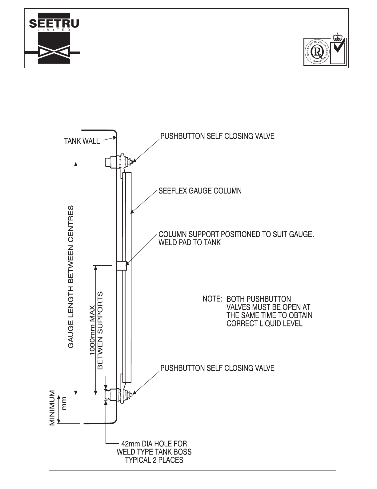
VALVE AT BOTTOM, VALVE AT TOP (see Figure 1)
This allows the column to be removed at any time. The tank connections are able to seal the tank even when
the level of liquid is above the gauge top fitting. This is the most common configuration.
Note: Both valves must be opened to obtain true reading of liquid level in tank.
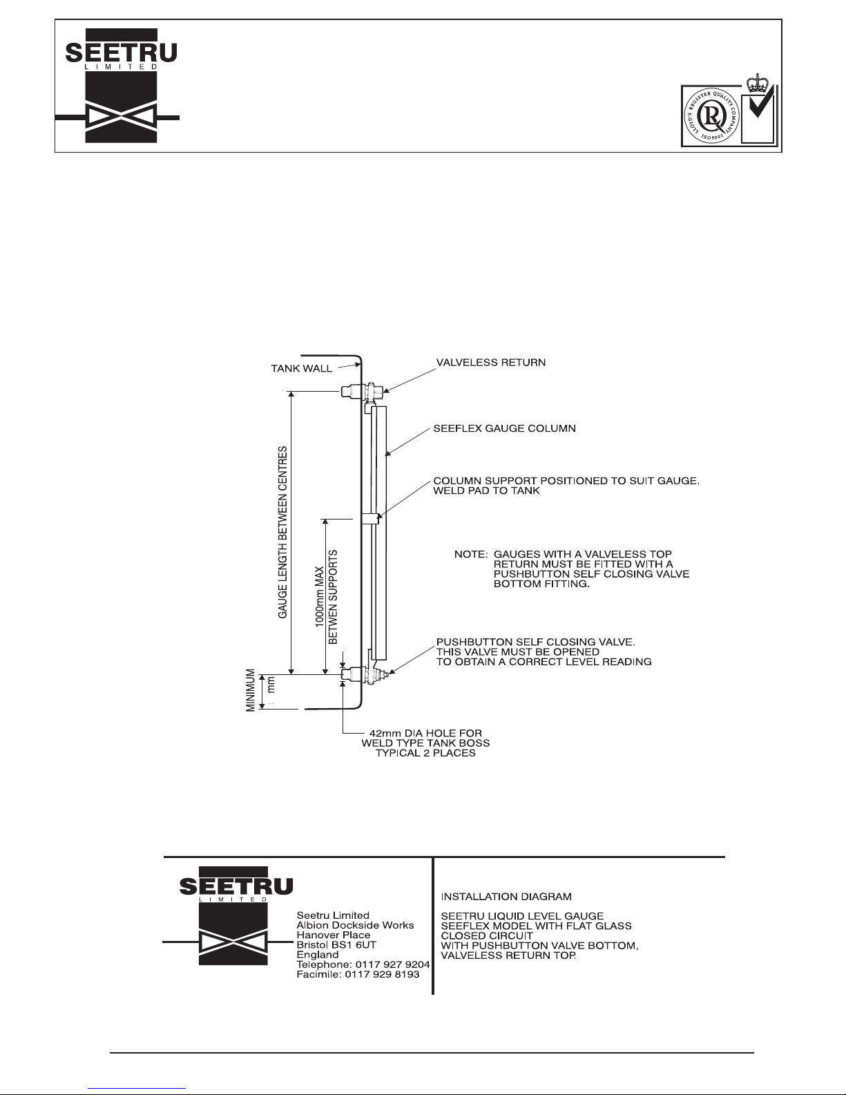
VALVE AT BOTTOM, VALVELESS RETURN AT TOP (see Figure 2)
The top fitting does not seal the tank from the gauge but provides a continuously open link. The top fitting
must always be above the maximum filling level of the tank. Valveless top return configuration must not be
used where the tank is pressurised.
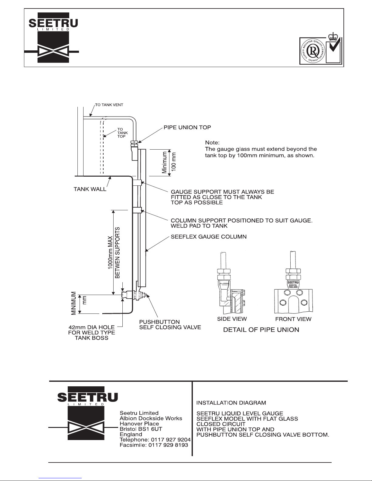
VALVE AT BOTTOM, PIPE UNION TO TANK AT TOP (see Figure 3)
The top fitting is connected to the tank top. This is useful when the tank is pressurised i.e. the small amount of
gas above the liquid in the gauge is pressurised to the same level as the gas above the liquid in the tank. The
column can only be removed when level of liquid in the tank is below the top fitting and the pressure has been
released.
OPEN CIRCUIT GAUGES
These gauges are mounted such that only the bottom fitting,which must be a push button valve, penetrates the
tank wall.
VALVE AT BOTTOM, PIPE UNION TO TANK VENT AT TOP (see Figure 3)
Similar configuration to Valve bottom, pipe union to tank top, except the top fitting is connected to the tank
vent.
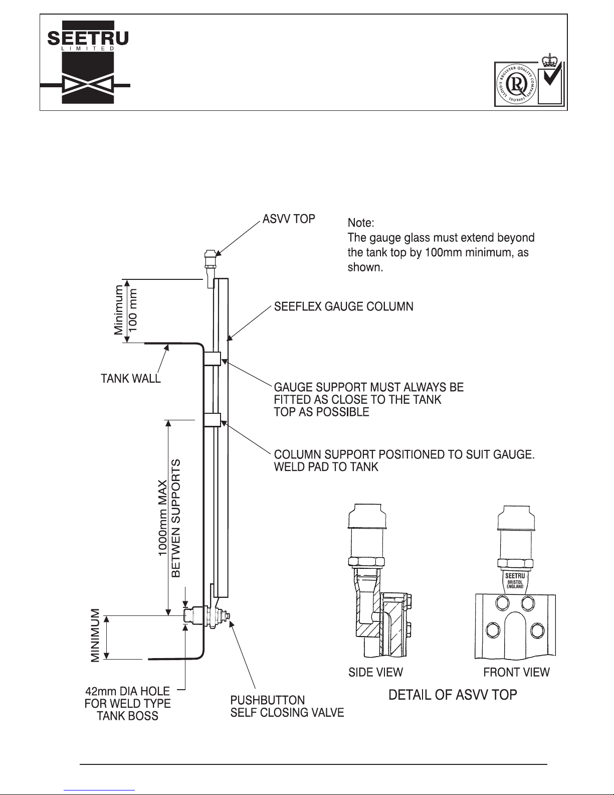
VALVE AT BOTTOM, AUTO SAFETY VENT VALVE AT TOP (ASVV) (see Figure 4)
The top fitting is connected to atmosphere through an ASVV. This unit allows air to enter or exit the top of the
gauge but does not allow liquid to leave the gauge.
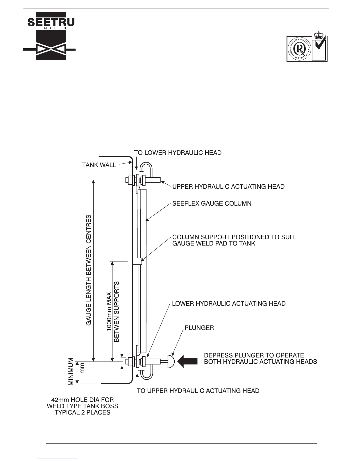
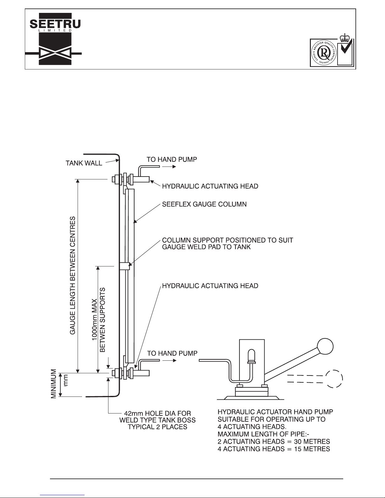
HYDRAULIC ACTUATION (see Figures 5 & 6)
Long gauges with valves top and bottom may be fitted with hydraulic actuation so that both vales are operated
simultaneously from a single location. The hydrualic actuation system may be fitted to existing gauges. For
further information on the hydraulic systems see the section starting on page 17.
Page 3
Seeflex Gauge Installation, Operating and Maintenance Instructions. Issue 4. 17.03.2008. G31INS
PAGE 3 OF 24
SEETRU LTD.
ALBION DOCKSIDE WORKS, HANOVER PLACE, BRISTOL BS1 6UT. ENGLAND.
TEL. 0117 927 9204. FAX 0117 929 8193.
INSTALLATION OPERATING &
MAINTENANCE INSTRUCTIONS
NATIONAL
ACCREDITATION
OF CERTIFICATION
BODIES
Figure 1.
VALVES FITTED TOP AND BOTTOM OF THE GAUGE.
38
Page 4
Seeflex Gauge Installation, Operating and Maintenance Instructions. Issue 4. 17.03.2008. G31INS
PAGE 4 OF 24
SEETRU LTD.
ALBION DOCKSIDE WORKS, HANOVER PLACE, BRISTOL BS1 6UT. ENGLAND.
TEL. 0117 927 9204. FAX 0117 929 8193.
INSTALLATION OPERATING &
MAINTENANCE INSTRUCTIONS
NATIONAL
ACCREDITATION
OF CERTIFICATION
BODIES
Figure 2.
VALVE AT BOTTOM, VALVELESS TOP RETURN
38
Page 5
Seeflex Gauge Installation, Operating and Maintenance Instructions. Issue 4. 17.03.2008. G31INS
PAGE 5 OF 24
SEETRU LTD.
ALBION DOCKSIDE WORKS, HANOVER PLACE, BRISTOL BS1 6UT. ENGLAND.
TEL. 0117 927 9204. FAX 0117 929 8193.
INSTALLATION OPERATING &
MAINTENANCE INSTRUCTIONS
NATIONAL
ACCREDITATION
OF CERTIFICATION
BODIES
Figure 3.
VALVE AT BOTTOM, PIPE UNION TO TANK TOP / TANK VENT
38
Page 6
Seeflex Gauge Installation, Operating and Maintenance Instructions. Issue 4. 17.03.2008. G31INS
PAGE 6 OF 24
SEETRU LTD.
ALBION DOCKSIDE WORKS, HANOVER PLACE, BRISTOL BS1 6UT. ENGLAND.
TEL. 0117 927 9204. FAX 0117 929 8193.
INSTALLATION OPERATING &
MAINTENANCE INSTRUCTIONS
NATIONAL
ACCREDITATION
OF CERTIFICATION
BODIES
Figure 4.
VALVE AT BOTTOM, AUTO SAFETY VENT VALVE AT TOP
38mm
Page 7
Seeflex Gauge Installation, Operating and Maintenance Instructions. Issue 4. 17.03.2008. G31INS
PAGE 7 OF 24
SEETRU LTD.
ALBION DOCKSIDE WORKS, HANOVER PLACE, BRISTOL BS1 6UT. ENGLAND.
TEL. 0117 927 9204. FAX 0117 929 8193.
INSTALLATION OPERATING &
MAINTENANCE INSTRUCTIONS
NATIONAL
ACCREDITATION
OF CERTIFICATION
BODIES
Figure 5.
HYDRAULIC ACTUATION SINGLE GAUGE
38
Page 8
Seeflex Gauge Installation, Operating and Maintenance Instructions. Issue 4. 17.03.2008. G31INS
PAGE 8 OF 24
SEETRU LTD.
ALBION DOCKSIDE WORKS, HANOVER PLACE, BRISTOL BS1 6UT. ENGLAND.
TEL. 0117 927 9204. FAX 0117 929 8193.
INSTALLATION OPERATING &
MAINTENANCE INSTRUCTIONS
NATIONAL
ACCREDITATION
OF CERTIFICATION
BODIES
Figure 6.
HYDRAULIC ACTUATION MULTIPLE GAUGE
38
Page 9

Seeflex Gauge Installation, Operating and Maintenance Instructions. Issue 4. 17.03.2008. G31INS
PAGE 9 OF 24
SEETRU LTD.
ALBION DOCKSIDE WORKS, HANOVER PLACE, BRISTOL BS1 6UT. ENGLAND.
TEL. 0117 927 9204. FAX 0117 929 8193.
INSTALLATION OPERATING &
MAINTENANCE INSTRUCTIONS
NATIONAL
ACCREDITATION
OF CERTIFICATION
BODIES
INSTALLATION INSTRUCTIONS
READ ALL INSTALLATION INSTRUCTIONS BEFORE COMMENCING WORK.
Important note
The Seeflex liquid level gauge is designed to be securely fitted to the side of a tank. Before the gauge is
mounted on the tank it is fragile and must be handled with care. Do not pick the gauge up from one end, when
lifting support the gauge along its entire length. If working on a bench the gauge must be rigidly supported at
least every 1000mm.
Tank Preparation.
Choose a position on the tank which is flat and unobstructed vertically to mount the gauge.
Carefully unpack the gauge and check the valve centre distance (if applicable)
For gauges with a valve at the bottom and either a valve or valveless fitting at the top, mark out two holes on the
tank wall at the same centre distance as the gauge centres. If your gauge has a valve at the bottom only,
mark the bottom hole only. These holes will locate the gauge and so must be positioned vertically.
The bottom hole must be above any known or suspected sludge levels.
Drill a 42mm diameter hole at each marked position.
Remove from the gauge valves from the tank bosses supplied.
Insert the bosses into the holes in the tank and weld into position.
Check that the boss bores are free of weld spatter. These bores may be protected with silicon grease prior to
welding.
Use Arosta 316L-150 (or equivalent) welding rods for mild steel tanks.
All welding must be to the satisfaction of classification surveyor.
Gauge (see Figure 10 on page 13 and Figure 11 on page 14)
Remove the isolation valves from the gauge by unscrewing the retaining nuts. Take care not to damage the collar
seals.
Screw the isolation valves into the tank bosses after first checking that the bosses are cold.
Support the gauge vertically, slide the gauge collars over the isolation valves (now protruding from the tank).
If the gauge valve centre distance is in excess of 1000mm intermediate supports are supplied. These require
packing plates (supplied) to be welded to the tank.
If present, equally space the support pads along the gauge at not more than 1000mm centres. Tack weld the
pads to the tank.
Loosen the support brackets and remove the gauge from the tank.
Complete the welding of the support pads.
Mount the gauge on the tank and tighten the support brackets. Check collar inner 'O' rings are in position.
Fit the outside ‘O’ rings to the top and bottom isolation valves, screw on the retaining nuts and tighten.
It is possible to adjust the gauge isolation valve centre distance on closed circuit gauges by plus or minus 5mm
by sliding the top gauge collar in or out.
If the top gauge collar is removed completely DO NOT PUSH IT BACK THROUGH THE GLAND, this would
damage the internal seals. If the gauge collar is pulled out follow this procedure;
Remove the gland nut, P.T.F.E. spacer, and ‘O’ ring from the gauge collar housing. Assemble these components
onto the gauge collar stem in this sequence: first, metal gland nut; second, white P.T.F.E. spacer; third, 'O' ring.
Then fit this assembly ino the gauge collar housing. When the collar is in the correct position screw the gland nut
in hand tight.
Page 10
Seeflex Gauge Installation, Operating and Maintenance Instructions. Issue 4. 17.03.2008. G31INS
PAGE 10 OF 24
SEETRU LTD.
ALBION DOCKSIDE WORKS, HANOVER PLACE, BRISTOL BS1 6UT. ENGLAND.
TEL. 0117 927 9204. FAX 0117 929 8193.
INSTALLATION OPERATING &
MAINTENANCE INSTRUCTIONS
NATIONAL
ACCREDITATION
OF CERTIFICATION
BODIES
Gauges Over 3.8 Metres in Length
Gauges over 3.8 metres are supplied split for packing. The gauge column sections must be joined together end
on end as installation progresses. This is easier done if the lower portion of the gauge is attached to the tank.
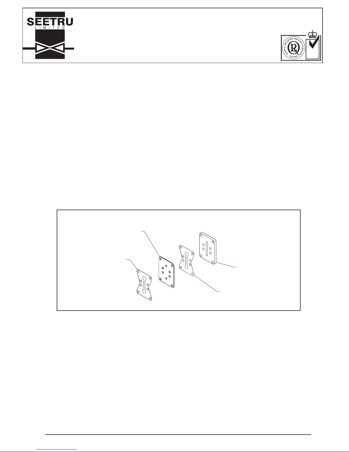
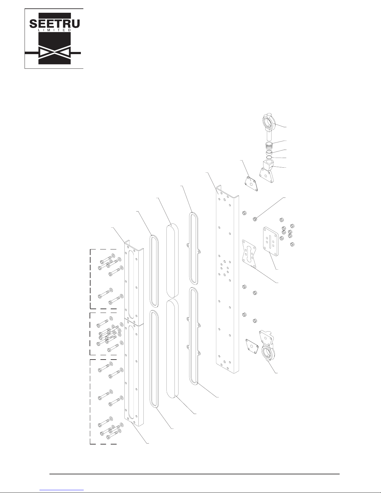
The connecting plate, stiffening plate and gaskets, assembled as shown in Figure 7, will already be fastened to
one gauge section, this should not be disturbed.
Remove the nuts and bolts from the gauge section which will join to the connecting plate. Fit the top gauge
section in position on lower gauge section, ensure that the gaskets are correctly alined. Refit the nuts and bolts
and tighten to 3Nm (26 lbs inches)
Continue the installation as though a one piece gauge.
WARNING
Connection plates are designed to join sections vertically and will not support the gauge sections in a horizontal
position.
COMMISSIONING
Fill the tank. Depress the push button in the centre of the isolation valves and the gauge will fill. Check the tank
boss and collar seals for leaks.
Note: Both valves must be opened to obtain true level reading.
The push button isolation valve completely isolates the tank contents, therefore if the collar seals leak, the collar
securing nut may be removed and the seals inspected. Removing the gauge column will not permit the tank
contents to leak, however any fluid in the gauge will be released. On gauges with valveless top return the column
or top seal can only be removed if liquid level is below the top fitting.
If the tank boss seal leaks, the push button isolating valve must be removed. The tank must be drained to a level
below the leaking valve before attempting this repair.
Figure 7
STIFFENING PLATE GASKET
STIFFENING PLATE
CONNECTION PLATE GASKET
CONNECTION PLATE
Page 11

Seeflex Gauge Installation, Operating and Maintenance Instructions. Issue 4. 17.03.2008. G31INS
PAGE 11 OF 24
SEETRU LTD.
ALBION DOCKSIDE WORKS, HANOVER PLACE, BRISTOL BS1 6UT. ENGLAND.
TEL. 0117 927 9204. FAX 0117 929 8193.
INSTALLATION OPERATING &
MAINTENANCE INSTRUCTIONS
NATIONAL
ACCREDITATION
OF CERTIFICATION
BODIES
MAINTENANCE
Figures in () refer to parts list on Figure 10. See also Figure 11.
A To remove and replace the gauge column from the tank
Note: Removing the gauge column from the tank will not cause the contents of the tank to be lost, provided that
the push button valves are closed i.e. their buttons are NOT depressed. Removing the gauge column from
the tank will cause any fluid in the gauge to drain out.
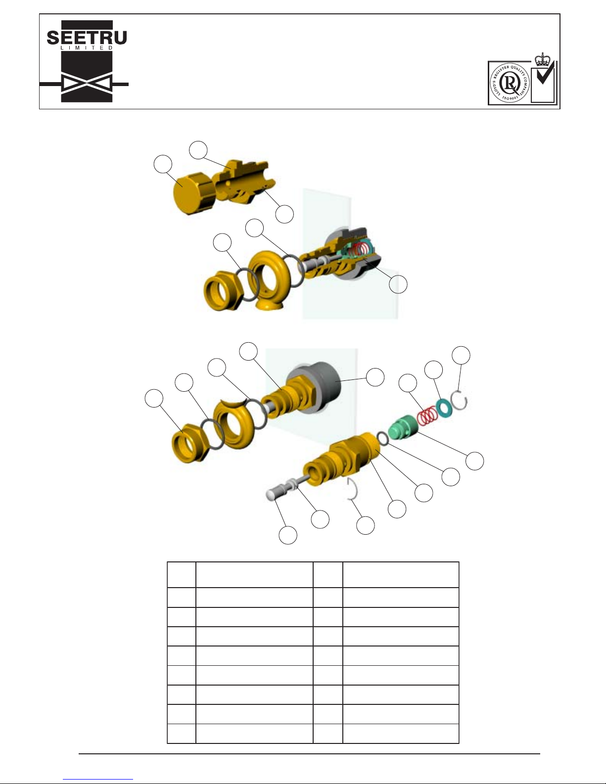
Remove the gauge retaining nuts (3)
Unscrew the intermediate support clamping bolts. Lift the gauge column away from the tank.
Take care not to drop the gauge column onto the bottom valve unit.
Remove and discard the collar 'O' ring seals (12).
Reverse the procedure to replace the gauge column, using new nuts for the intermediate clamping bolts and new
'O’ rings for the collar seal.
B To replace a reflex glass unit or reflex glass unit gasket
Any section of the Seeflex gauge column assembly can be dismantled and reassembled in position against the
tank. Care must be taken when doing so as any liquid contents within or above the section being maintained will
be released. Alternatively, the column may be removed from the tank by reference to maintenance paragraph A
above.
1. DISMANTLE PROCEDURE
Remove M6 nuts and bolts from the section to be dismantled.
Remove front bezel.
Remove cushion gasket
Remove reflex glass
Remove reflex seal
2. CLEANING
Use clean cloth and mild detergent.
Clean glass.
Clean exposed back channel to ensure any deposited trace of gasket is removed. It is important not to
damage the back channel surface as even the smallest abrasion may cause the column to leak.
If the connection plate or collar units are dismantled, clean the gasket faces ensuring the sealing face is
not damaged.
3. REPLACEMENT PARTS
Always use new reflex seals.
Always use new connection plate gaskets (if dismantled).
Always use new collar gaskets (if dismantled).
Always use new M6 ‘nyloc’ nuts.
Cushion gasket can be reused if in good condition.
Glass can be reused if in good condition.
Bolts can be reused if in good condition.
4. RE-ASSEMBLY
Reassemble in reverse order and as shown in Figure 11.
Page 12
Seeflex Gauge Installation, Operating and Maintenance Instructions. Issue 4. 17.03.2008. G31INS
PAGE 12 OF 24
SEETRU LTD.
ALBION DOCKSIDE WORKS, HANOVER PLACE, BRISTOL BS1 6UT. ENGLAND.
TEL. 0117 927 9204. FAX 0117 929 8193.
INSTALLATION OPERATING &
MAINTENANCE INSTRUCTIONS
NATIONAL
ACCREDITATION
OF CERTIFICATION
BODIES
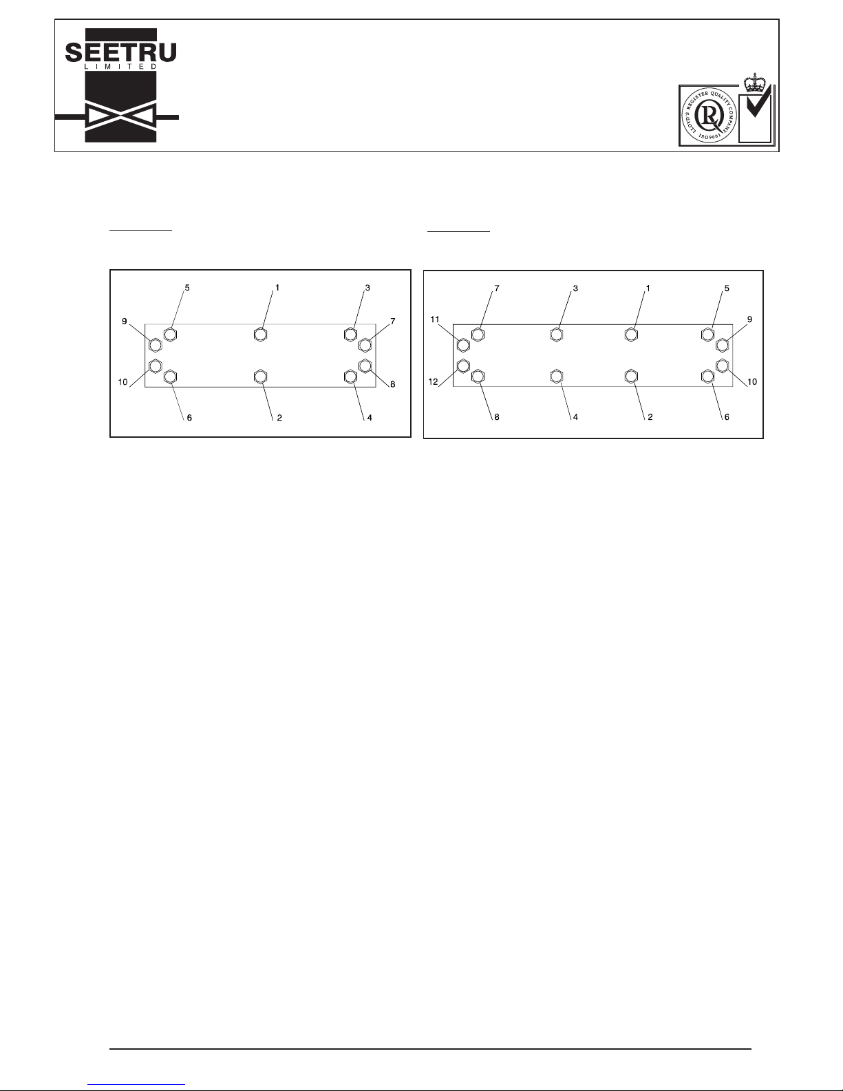
After complete re-assembly and before allowing liquid into gauge, check all bolts are
tight to 3 Nm in the sequence shown.
No. 9 Section
Progressively torque bolts to 3 Nm in sequence shown below.
No. 6 Section
Progressively torque bolts to 3 Nm in sequence shown below.
5. TORQUE TIGHTENING SEQUENCE
C To replace push rod 'O' ring (11)
Important; The liquid level in the tank must be below the push button valve before the push
rod is removed. Removing the push rod will allow the tank contents to drain out.
Remove retaining clip (9)
Remove push rod (4)
Inspect or replace 'O' ring (11)
Check for obstructions
Reassemble in reverse order.
D To inspect or replace tank boss 'O' ring (7)
Drain tank to below level of connection
Remove gauge from tank as described in maintenance paragraph A
Unscrew and remove valve unit from tank boss
Inspect 'O' ring (7) replace if necessary
Check bore in tank boss is smooth and clean
Reassemble in reverse order.
E To inspect or replace shut off valve 'O' ring seal (13) or shut off valve spring (8)
Drain tank to below level of connection
Remove gauge from tank as described in maintenance paragraph A
Unscrew and remove valve unit from tank boss (1)
Remove circlip (10) from rear of unit
Remove spacer (6)
Inspect or replace spring (8)
Remove shut of valve (5)
Inspect or replace 'O' ring (13)
Check internal passage of body (2) to be free of obstructions
Inspect and wipe clean bore and valve seating
Check bore in tank boss (1) to be smooth and clean
Inspect 'O' ring (7) replace if necessary
Reassemble in reverse order.
Figure 8
Figure 9
Page 13
Seeflex Gauge Installation, Operating and Maintenance Instructions. Issue 4. 17.03.2008. G31INS
PAGE 13 OF 24
SEETRU LTD.
ALBION DOCKSIDE WORKS, HANOVER PLACE, BRISTOL BS1 6UT. ENGLAND.
TEL. 0117 927 9204. FAX 0117 929 8193.
INSTALLATION OPERATING &
MAINTENANCE INSTRUCTIONS
NATIONAL
ACCREDITATION
OF CERTIFICATION
BODIES
Figure 10. VALVE PARTS LIST & DIAGRAM
METI
.oN
NOITPIRCSED
METI
.oN
NOITPIRCSED
1SSOBKNAT9PILCGNINIATER
2YDOBEVLAVNOTTUBHSUP01PILCRIC
3TUNGNINIATER11GNIR'O'
DORHSUP
4DORHSUP21SGNIR'O'RALLOC
5EVLAVFFOTUHS31EVLAVFFOTUHS
6RECAPS41TUNGNINIATERDNILB
7GNIR'O'SSOBKNAT51YDOBELPPIND
NILB
8GNIRPSEVLAVFFOTUHS
14
15
7
12
12
7
3
12
12
9
1
4
11
9
7
2
13
8
6
5
10
Page 14
Seeflex Gauge Installation, Operating and Maintenance Instructions. Issue 4. 17.03.2008. G31INS
PAGE 14 OF 24
SEETRU LTD.
ALBION DOCKSIDE WORKS, HANOVER PLACE, BRISTOL BS1 6UT. ENGLAND.
TEL. 0117 927 9204. FAX 0117 929 8193.
INSTALLATION OPERATING &
MAINTENANCE INSTRUCTIONS
NATIONAL
ACCREDITATION
OF CERTIFICATION
BODIES
Figure 11. GAUGE COLUMN PARTS DIAGRAM
GAUGE COLLAR
GLAND NUT
P.T.F.E. SPACER
COLLAR O'RING
GAUGE COLLAR
HOUSING
COLLAR GASKET
M6 NYLOC NUT
CONNECTION PLATE
CONNECTION PLATE
GASKET
LOWER COLLAR PLATE
BACK CHANNEL
No. 6 REFLEX SEAL
No. 6 REFLEX GLASS
No. 6 CUSHION GASKET
No. 6 FRONT BEZEL
No. 9 FRONT BEZEL
No. 9 CUSHION GASKET
No. 9 REFLEX GLASS
No. 9 REFLEX SEAL
M6 x 35mm
M6 x 40mm
M6 x 35mm
Page 15

Seeflex Gauge Installation, Operating and Maintenance Instructions. Issue 4. 17.03.2008. G31INS
PAGE 15 OF 24
SEETRU LTD.
ALBION DOCKSIDE WORKS, HANOVER PLACE, BRISTOL BS1 6UT. ENGLAND.
TEL. 0117 927 9204. FAX 0117 929 8193.
INSTALLATION OPERATING &
MAINTENANCE INSTRUCTIONS
NATIONAL
ACCREDITATION
OF CERTIFICATION
BODIES
EMERGENCY INSTRUCTIONS
No special emergency instructions apply to this type of gauge. Due to its design the volume of liquid in the
gauge is isolated from the tank content and remains so unless a reading is actually being taken.
If the gauge is broken the small amount of liquid in the gauge glass will be lost, but the tank will remain sealed
off.
OPERATING INSTRUCTIONS TO READ LEVEL IN TANK
1. Depress the top valve, if fitted, and hold open
2. Depress the bottom valve an hold open. The level inside the tank should now register in the gauge glass.
3. When the liquid level settles release the valves to seal off the gauge from tank.
Note: The level shown in the sight tube will remain at this point. When a new reading is required repeat the above
operations.
Note: If hydraulic actuator is fitted
1. Depress plunger knob/lever on actuator which will open both valves simultaneously. Hold knob/lever until
liquid level settles in the gauge.
2. Release knob/lever to seal off gauge form tank.
It should be noted that on gauges fitted with valves in top and bottom connections, the tank level shown may be
incorrect if the bottom valve alone is operated. This is due to the trapping of air between the liquid and the upper
valve. This would not occur in gauges fitted with a blind nipple assembly in the upper connection, as with this
connection the top of the sight tube is always open to the tank.
Page 16
Seeflex Gauge Installation, Operating and Maintenance Instructions. Issue 4. 17.03.2008. G31INS
PAGE 16 OF 24
SEETRU LTD.
ALBION DOCKSIDE WORKS, HANOVER PLACE, BRISTOL BS1 6UT. ENGLAND.
TEL. 0117 927 9204. FAX 0117 929 8193.
INSTALLATION OPERATING &
MAINTENANCE INSTRUCTIONS
NATIONAL
ACCREDITATION
OF CERTIFICATION
BODIES
OPERATING FAULTS
Faults Probable Cause Rectification
Maintenance
Paragraph
Gauge not filling Empty Tank
Obstruction in gauge
Obstruction in body
Fill
Clear
Clear
A
E
Filling to Incorrect
level
Incorrect use of gauge See operation instructions
Broken sight glass Misuse
Misalignment
Replace glass
Replace glass - check
tank face flat
B
Main valve not
sealing
'O' ring damaged
Broken spring
Replace
Replace
E
E
L
eaks from:-
Collar seal
Sight glass /
gaskets
Tank boss
Push rod
Loose nut
'O' ring damaged
Loose front bezel
Damaged gaskets
'O' ring damaged
'O' ring damaged
Tighten
Replace
Tighten bolts in sequence
Replace
Replace
Replace
A
A
B
B
D
C
Page 17

Seeflex Gauge Installation, Operating and Maintenance Instructions. Issue 4. 17.03.2008. G31INS
PAGE 17 OF 24
SEETRU LTD.
ALBION DOCKSIDE WORKS, HANOVER PLACE, BRISTOL BS1 6UT. ENGLAND.
TEL. 0117 927 9204. FAX 0117 929 8193.
INSTALLATION OPERATING &
MAINTENANCE INSTRUCTIONS
NATIONAL
ACCREDITATION
OF CERTIFICATION
BODIES
INSTALLATION AND OPERATION
(see Figure 5 & Figure 12)
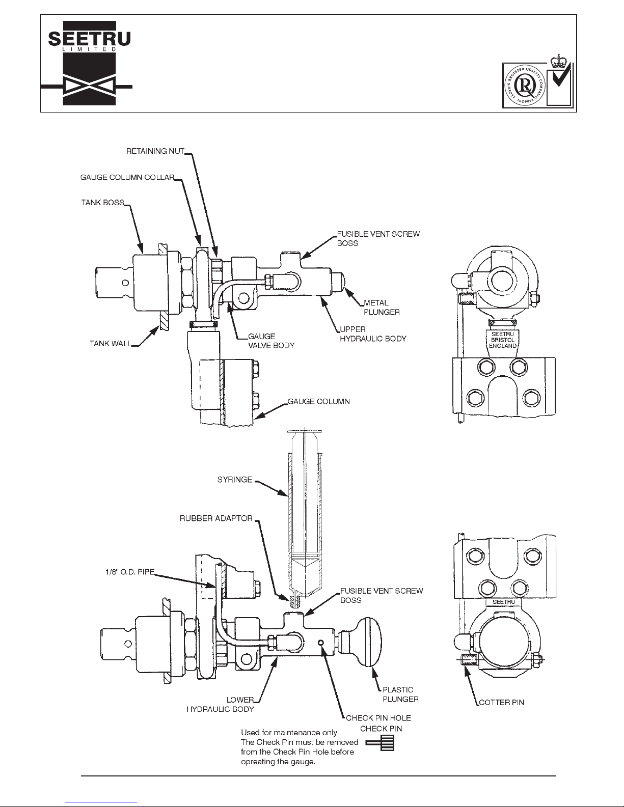
The diagram on page 19 shows the plastic push button in the lower position, however the gauge may be
specified with the push button at either end. When mounting the gauge to the tank ensure that the fusible vent
screw boss on each hydraulic head is pointing upwards.
Should the temperature surrounding the gauge exceed 147°F the fusible vent screws will melt. This renders the
hydraulic system ineffective and hence prevents the isolating valves being opened due to thermal expansion of
the hydraulic oil.
Gauges up to 3800 centres
These gauges will be packed complete with valves and hydraulic actuator system in position. The system will
be charged with hydraulic fluid checked and be ready for use before it is despatched. To fit the gauge;
1. Remove the tank bosses from the gauge valves and weld them to the tank. For full details see Installation
instructions on page 9.
2. Remove the cotter pins which hold the upper and lower hydraulic bodies to the gauge valve bodies.
3. Slide the upper and lower hydraulic bodies complete with the 1/8” o.d. pipe from the valve bodies.
4. Remove the retaining nuts from valve bodies.
5. Slide the valves out of the gauge column collars.
6. Screw the valves into the tank bosses.
7. Refit the gauge column onto the valve bodies.
8. Refit the retaining nuts onto the valve bodies and tighten.
9. Refit the upper and lower hydraulic bodies onto the valve bodies. The 1/8” o.d. pipe must be fitted on the
left hand side behind the back channel of the gauge column. Note, the fusible vent screw boss on each
hydraulic body must face upwards.
10. Refit the cotter pins into the upper and lower hydraulic bodies, fit nuts to cotter pins and tighten.
11. To operate the gauge fully depress the black plastic plunger on the hydraulic body and hold until the level
of the fluid in the gauge stabilises. Release the knob and take the tank level reading. The gauge is now
isolated from the tank contents.
Gauges over 3800 centres (see also 'Gauges over 3.8m in length' on page 10)
These gauges will have the gauge column split for packing. The hydraulic system will be supplied complete,
charged with hydraulic fluid checked and ready for use, but the pipe will be coiled i.e. not fitted to the gauge
column. To fit the gauge to the tank follow instructions 1,4,5,6,7 and 8 for gauges up to 3800 centres as above.
Join the 2 halves of the gauge column together before attempting instruction 7. Complete the installation by
following the instructions below.
9. Straighten the coiled 1/8” o.d. pipe and fit the upper and lower hydraulic bodies onto the valve bodies. The
pipe must be fitted on the left hand side behind the back channel of the gauge column. Note, the fusible
vent screw boss on each hydraulic body must face upwards.
10. Fit the cotter pins into the upper and lower hydraulic bodies, fit nuts to cotter pins and tighten
11. To operate the gauge fully depress the black plastic plunger on the hydraulic body and hold until the level
of the fluid in the gauge stabilises. Release the knob and take the tank level reading. The gauge is now
isolated from the tank contents.
HYDRAULIC ACTUATION
SINGLE GAUGE SYSTEM
Page 18

Seeflex Gauge Installation, Operating and Maintenance Instructions. Issue 4. 17.03.2008. G31INS
PAGE 18 OF 24
SEETRU LTD.
ALBION DOCKSIDE WORKS, HANOVER PLACE, BRISTOL BS1 6UT. ENGLAND.
TEL. 0117 927 9204. FAX 0117 929 8193.
INSTALLATION OPERATING &
MAINTENANCE INSTRUCTIONS
NATIONAL
ACCREDITATION
OF CERTIFICATION
BODIES
INSTRUCTIONS FOR FILLING AND REMOVING AIR
FROM THE HYDRAULIC SYSTEM
The Hydraulic system is supplied by Seetru filled and ready for use. These instructions are required only when
the hydraulic system has been drained of fluid. See also Figure 12 on page 19.
1. Assemble the rubber adaptor onto the syringe body
2. Remove the plunger from the syringe body
3. Remove the fusible vent screws from both the upper and lower hydraulic bodies.
4. Inset the syringe into the lower hydraulic body fusible vent screw hole.
5. Pour at least 30ml of hydraulic oil into the syringe and replace the plunger. Use the oil supplied with the
filling kit or hydraulic oil type S.A.E. 70R3 or S.A.E. J1703B
6. Depress the plunger in the syringe until hydraulic fluid reaches the top of the fusible vent screw boss in the
upper hydraulic body
7. Replace the fusible vent screw in the upper hydraulic body and tighten
8. Push in the lower hydraulic body plunger at least 3mm and hold in whilst fitting the check pin into the
1.0mm dia hole in the left hand side of the lower hydraulic body. Release pressure on the plunger and allow
it to move back against the check pin. This operation prevents the gauge being opened due to thermal
expansion of the hydraulic oil.
9. Remove the syringe. Refit the fusible vent screw in the lower hydraulic body and tighten.
10. Make sure both fusible vent screws are tightened and not leaking.
11. Remove the check pin.
12. To operate the gauge fully depress the black plastic knob on the hydraulic body and hold until the level of
the fluid in the gauge stabilises. Release the knob and take the tank level reading. The gauge is now
isolated from the tank contents.
If the valves do not operate correctly repeat the whole operation.
If air enters the hydraulic system the gauge valves may not open fully. This could result in a delay in obtaining a
true reading of the liquid level in the tank i.e. the fluid will be restricted when flowing into the gauge. If this occurs
carry the instructions above except item 6 which should be replaced with the following.
6. Insert a short length of clean flexible hose into the top fusible vent screw hole; insert the other end of the
hose into a clear jar containing hydraulic oil type S.A.E. 70R3 or S.A.E. J1703B. Depress the plunger in the
syringe, hydraulic oil will flow into the clear jar, continue until no air bubbles are present in the hydraulic oil
leaving the gauge.
HYDRAULIC ACTUATION
SINGLE GAUGE SYSTEM
Page 19
Seeflex Gauge Installation, Operating and Maintenance Instructions. Issue 4. 17.03.2008. G31INS
PAGE 19 OF 24
SEETRU LTD.
ALBION DOCKSIDE WORKS, HANOVER PLACE, BRISTOL BS1 6UT. ENGLAND.
TEL. 0117 927 9204. FAX 0117 929 8193.
INSTALLATION OPERATING &
MAINTENANCE INSTRUCTIONS
NATIONAL
ACCREDITATION
OF CERTIFICATION
BODIES
Figure 12.
Hydraulic Actuation Single Gauge System
Page 20

Seeflex Gauge Installation, Operating and Maintenance Instructions. Issue 4. 17.03.2008. G31INS
PAGE 20 OF 24
SEETRU LTD.
ALBION DOCKSIDE WORKS, HANOVER PLACE, BRISTOL BS1 6UT. ENGLAND.
TEL. 0117 927 9204. FAX 0117 929 8193.
INSTALLATION OPERATING &
MAINTENANCE INSTRUCTIONS
NATIONAL
ACCREDITATION
OF CERTIFICATION
BODIES
HYDRAULIC ACTUATION
MULTI-GAUGE SYSTEM
GENERAL DESCRIPTION.
(See Figures 6, 13, 14 & 15)
Seetru hydraulic actuation systems are made to measure and should be installed as received. Each hydraulic
actuator head pump unit can operate up to four Seetru Marine push button valves simultaneously. For
installations incorporating more than four actuator heads, two or more pump units are necessary. These can be
grouped conveniently so that the handles can be operated simultaneously. The pump unit can be placed in any
convenient position, either on the wall of the vessel or remote from it within maximum lengths of copper tube
runs specified below.
Number of Actuator Heads Maximum Length of pipe in meters
1 60m
2 30m
3 20m
4 15m
INSTALLATION
1. The push button valves in the gauge should be free and working properly.
2. The actuator head must be positioned with the vent screw boss uppermost, squarely and securely fastened
to the gauge valve by the cotter pin provided.
3. The actuator head override push buttons should be “out”.
4. The actuator pump vent plug should be uppermost, and the unit securely fastened to a rigid structure.
5. All units to be piped together with half hard copper tube installed free of kinks and sharp bends. All
connections should be properly sealed.
6. Hydraulic oil is supplied with the filling kit. Alternatively use hydraulic oil type S.A.E. 70R3 or S.A.E. J1703B
FILLING
Before filling commences, check that the gauge has been correctly installed.
1. Remove all fusible vent screws.
2. Screw or push in filler in top actuator head vent screw boss.
3. Fill filler reservoir with hydraulic oil. Allow the system to fill by gravity, keep a level in the filler reservoir at all
times. As discharge is observed from lower vent screw boss, wait until bubbles cease and all air is vented
from the pipe and actuator pump equipment. Refit vent screws.
4. Before removing filler, observe level in reservoir and work actuator pump. There will be considerable
agitation in the reservoir.
5. Remove filler and fill top vent screw boss with hydraulic fluid. Fit top vent screw,
Work actuator pump handle. Resistance should be felt. The isolating valves will open, gauge column will fill if
tank contains liquid. If tank contains heavy viscous fluid, actuator pump handle must be held in whilst gauge
column fills slowly.
If no resistance is felt and gauge column does not fill (Isolating valves not opening) the system will still contain
air. Proceed as follows.
Page 21

Seeflex Gauge Installation, Operating and Maintenance Instructions. Issue 4. 17.03.2008. G31INS
PAGE 21 OF 24
SEETRU LTD.
ALBION DOCKSIDE WORKS, HANOVER PLACE, BRISTOL BS1 6UT. ENGLAND.
TEL. 0117 927 9204. FAX 0117 929 8193.
INSTALLATION OPERATING &
MAINTENANCE INSTRUCTIONS
NATIONAL
ACCREDITATION
OF CERTIFICATION
BODIES
HYDRAULIC ACTUATION
MULTI-GAUGE SYSTEM
VENTING
1. Remove vent screw on top actuator head.
2. Fit filler and recharge reservoir.
3. Operate actuator pump handle and observe discharge of air bubbles if any. When clear, remove filler, fill
vent screw boss, and refit vent screw.
Work actuator pump handle. Resistance should be felt. The Isolating valves will open, gauge column will fill if
tank contains liquid. If tank contains heavy viscous fluid, actuator pump handle must be held in whilst gauge
column fills slowly. If no resistance is felt and gauge column does not fill (Isolating valves not opening) the
system will still contain air. Proceed as follows.
4. Remove vent screw on actuator pump.
5. Fit filler on actuator pump and recharge reservoir. Operate actuator pump handle and observe discharge of
air bubbles if any. When clear, remove filler, fill vent screw boss and refit vent screw.
Work actuator pump handle. Resistance should be felt. Isolating valves will open, gauge column will fill if tank
contains liquid. If tank contains heavy viscous fluid actuator pump handle must be held in whilst gauge column
fills slowly. If no resistance is felt and gauge column does not fill (Isolating valves not opening) the system will
still contain air.
Proceed as follows.
6. Remove vent plug on lower actuator head. Fit filler on lower actuator head and recharge reservoir. Operate
actuator pump handle and observe discharge of air bubbles if any, When clear, remove filler, fill vent screw
boss and refit vent screw,
Work actuator pump handle. Resistance should be felt. Isolating valves will open, gauge column will fill if tank
contains liquid. If tank contains heavy viscous fluid, actuator pump handle must be held in whilst gauge column
fills slowly. If no resistance is felt and gauge column does not fill (Isolating valves not opening) the system will
still contain air. Check all pipe joints for leaks and repeat the whole venting procedure.
If resistance is felt when working actuator pump then system is now completely purged of air and all vent
screws are tight.
SETTING
See Figure 13
Page 22

Seeflex Gauge Installation, Operating and Maintenance Instructions. Issue 4. 17.03.2008. G31INS
PAGE 22 OF 24
SEETRU LTD.
ALBION DOCKSIDE WORKS, HANOVER PLACE, BRISTOL BS1 6UT. ENGLAND.
TEL. 0117 927 9204. FAX 0117 929 8193.
INSTALLATION OPERATING &
MAINTENANCE INSTRUCTIONS
NATIONAL
ACCREDITATION
OF CERTIFICATION
BODIES
HYDRAULIC ACTUATION
MULTI-GAUGE SYSTEM
OPERATION
To operate this system, depress actuator pump handle and hold down lever. If isolating valves do not open see
Fault Finding section below. Actuator heads are fitted with a push button for manual emergency operation.
When used, the hydraulic system is overridden.
MAINTENANCE
The vent screw boss's have fusible alloy inserts (vent screws). If fluid loss is experienced following a fire in the
vicinity of the system fit new vent screws and refill system working through sections Filling, Venting and Setting.
No standard maintenance is required. If system is not working properly, or has been dismantled and
disconnected, work through Filling, Venting and Setting instructions.
FAULT FINDING
FAULT CAUSE CURE
No level in the gauge glass Empty tank Fill
Gauge valves not opening
Gauge valves not opening Loose actuation head See Installation section
Air in system Work through Filling, Venting and
Setting sections
Fluid Loss See Maintenance and Filling,
Venting and Setting sections
Broken Pipe See Filling, Venting and Setting
sections.
Leaking connection Tighten. See Installation section.
Page 23
Seeflex Gauge Installation, Operating and Maintenance Instructions. Issue 4. 17.03.2008. G31INS
PAGE 23 OF 24
SEETRU LTD.
ALBION DOCKSIDE WORKS, HANOVER PLACE, BRISTOL BS1 6UT. ENGLAND.
TEL. 0117 927 9204. FAX 0117 929 8193.
INSTALLATION OPERATING &
MAINTENANCE INSTRUCTIONS
NATIONAL
ACCREDITATION
OF CERTIFICATION
BODIES
HYDRAULIC ACTUATION
MULTI-GAUGE SYSTEM
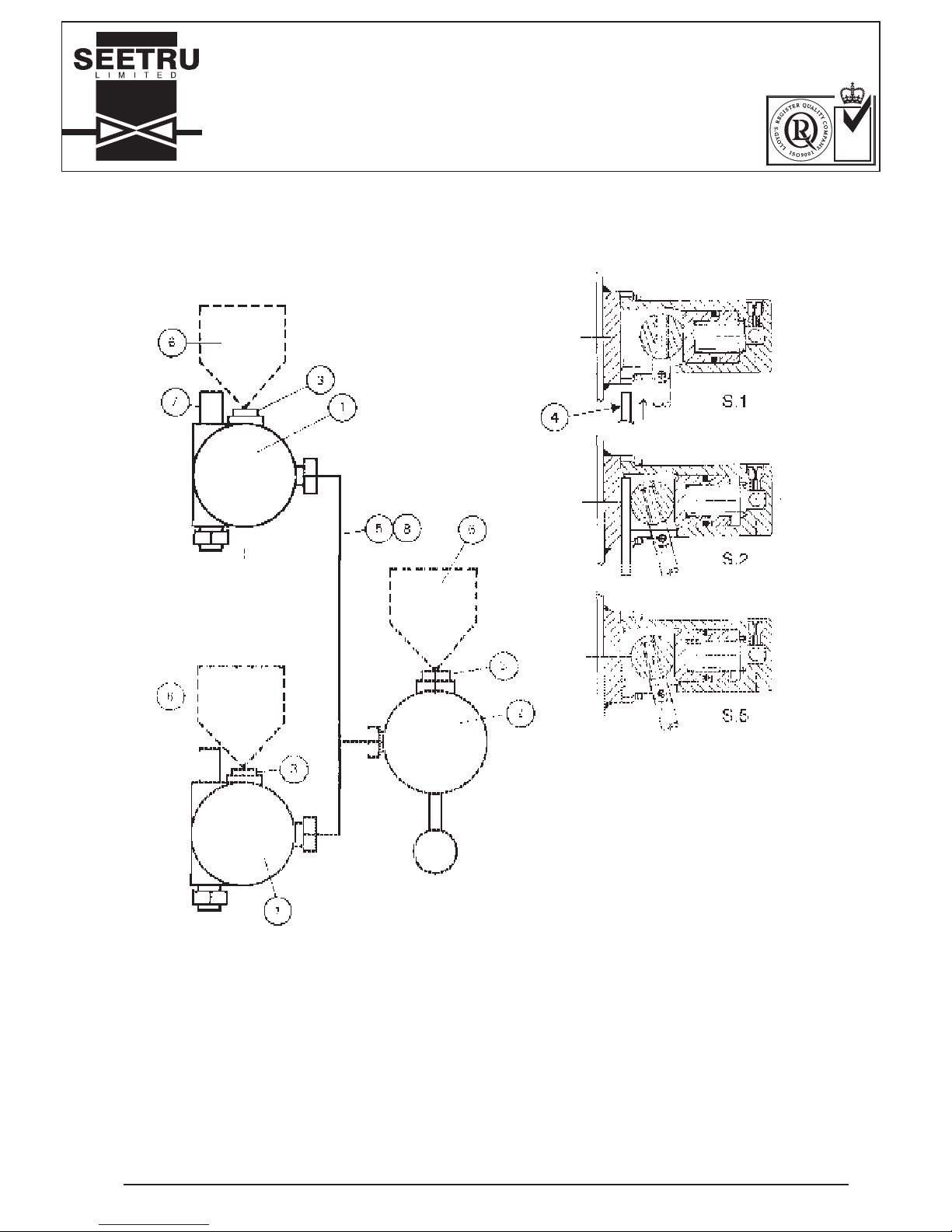
Figure 13.
SETTING INFORMATION
ITEM
1. Actuator head
2. Actuator pump
3. Fusible vent screw
4. Setting Gauge
5. Tube
6. Filler
7. Cotter Pin
8. Fluid
S.1 Depress actuator pump handle to open
isolating valves. Hold open and hold setting
gauge in position
S.2 Allow actuator to return until gripping setting
gauge.
S.3 Ease back vent plug on actuator. /Fluid will
vent off as gauge valves close.
S.4 Tighten fusible vent screws
S.5 Remove setting gauge
SETTINGPARTS LIST
Page 24
Seeflex Gauge Installation, Operating and Maintenance Instructions. Issue 4. 17.03.2008. G31INS
PAGE 24 OF 24
SEETRU LTD.
ALBION DOCKSIDE WORKS, HANOVER PLACE, BRISTOL BS1 6UT. ENGLAND.
TEL. 0117 927 9204. FAX 0117 929 8193.
INSTALLATION OPERATING &
MAINTENANCE INSTRUCTIONS
NATIONAL
ACCREDITATION
OF CERTIFICATION
BODIES
HYDRAULIC ACTUATION
MULTI-GAUGE SYSTEM
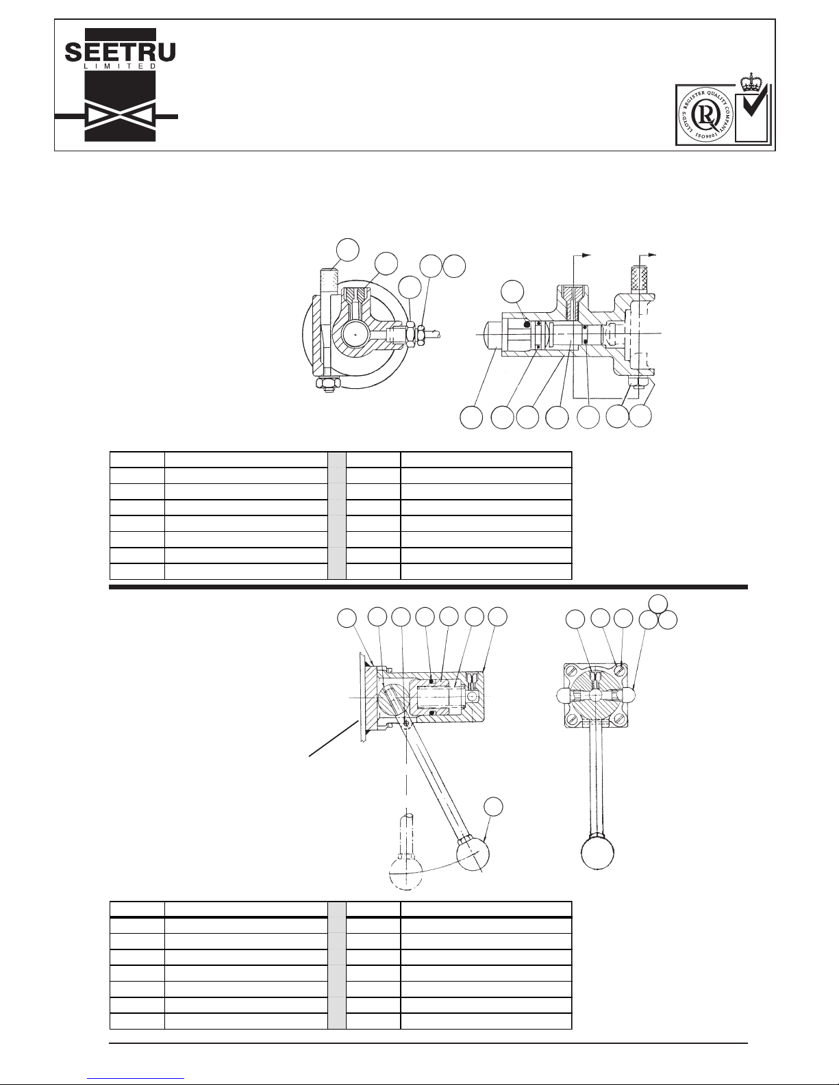
ITEM No. DESCRIPTION ITEM No. DESCRIPTION
1 TANK PAD 8 FUSIBLE VENT SCREW
2 HANDLE ASSEMBLY 9 CLAMP SCREW
3 PIVOT PIN 10 WASHER
4 'O' RING 11 TUBE FITTING; ELBOW
5 PISTON 12 TUBE FITTING; OLIVE
6 SPRING 13 TUBE FITTING; TUBE NUT
7 BODY 14 KNOB
RIGID MOUNTING STRUCTURE. REF.
1
2345 67
8
9
10
11
12 13
14
ITEM No. DESCRIPTION ITEM No. DESCRIPTION
1 COTTER PIN 8 PUSH BUTTON
2 FUSIBLE VENT SCREW 9 'O' RING
3 REDUCING CONNECTOR 10 BODY
4 TUBE FITTING; OLIVE 11 PLUNGER
5 TUBE FITTING; TUBE NUT 12 'O' RING
6 13 NUT
7 LOCKING PIN 14 WASHER
PARTS LIST
PARTS LIST
89
4
3
2
1
5
13
11
14
1210
7
Figure 14.
ACTUATOR HEAD
Figure 15.
ACTUATOR PUMP
 Loading...