

Page 1
CPI TUBULAR GAUGE G23
INSTALLATION, OPERATING &
MAINTENANCE INSTRUCTIONS
SEETRU LIMITED
ALBION DOCKSIDE WORKS, HANOVER PLACE, BRISTOL BS1 6UT. ENGLAND
TEL. 0117 9279 204. FAX 0117 929 8193.
EMAIL: [email protected]
WEB: www.seetru.com
1
GENERAL
The CPI Tubular gauge is desig ned and constructed to provide direct level observation of liquids,
including chemicals and solvents. The gauge column is fixed to the outside of a tank and isolat ed from
the tank by screw down valves which control the flow of liquid into the column and isolate the gauge
when completely closed.
Each isolating valve incorporates an automatic safet y valve. Should the sight glass be broken, the
abnormal flow of liquid acting on t he ball in the valve, forces it forward onto the seat in the valve body,
thereby checking the flow of liquid until the isolating valves can be closed.
Warning: The automatic saf et y valves are only able to operate when the isolating valves are fully open.
It is vital that the isolating valves are always left in a fully open or fully closed position. Never
leave them in a partially open position.
The isolating valves and valveless units are constructed of stainless steel 316 wetted par t s, PTFE seals
and plastic handwheel. Other parts of the valves are constructed in st ainless st eel.
THE TUBULAR COLUMN ASSEMBLY
There are two types of Tubular Column Assemblies:
1. Tubular borosilicate glass tube protected by a stainless st eel guard tube, model G231.
2. Tubular borosilicate glass tube protected by a stainless st eel guard tube, as above, but further
protected by a polycarbonate tube which completely covers the stainless steel guard tube, m odel
G232.
All metal parts are rust proofed.
GAUGES FITTED WITH ISOLATING VALVES TOP AND BOTTOM
On these gauges the column can be removed without draining t he tank. Before removal close both
isolating valves and drain the column.
GAUGES FITTED WITH ISOLATING VALVE AT BOTTOM ONLY AND A VALVELESS UNIT AT THE
TOP
On these gauges the tank contents must be below the top unit, the bottom isolating valve must be closed
and the column drained before attempting to remove the column.
Note: Valveless units should not be fitted on pressurised tanks or installed on other tank below the
highest liquid level, as they cannot be fitt ed with auto safety valves (ASV).
Sampling/Drain Valves or Drain/Vent Plugs should be fitted to isolating valves if tank needs to be
drained.
Page 2

CPI TUBULAR GAUGE G23
INSTALLATION, OPERATING &
MAINTENANCE INSTRUCTIONS
SEETRU LIMITED
ALBION DOCKSIDE WORKS, HANOVER PLACE, BRISTOL BS1 6UT. ENGLAND
TEL. 0117 9279 204. FAX 0117 929 8193.
EMAIL: [email protected]
WEB: www.seetru.com
2
APPLICATION
Use the CPI Tubular gauge only with fluids which guarantee r eliable function, and to which the materials
employed that come into contact with the fluid are adeq uat ely resist ant .
In addition: No heavy soiling
No coarse particles
No crystallization
INSTALLATION
Installation must be undertaken by a qualified technician and to good engineering practice. In addition,
users attention is drawn to our joint responsibility to ensure that the health and safety at work act is not
contravened by incorrect installation, commissioning or servicing.
Fitting Gauge to Tank:
1. Ensure that the tank flanges are vertically in line with each other and that the flange faces are
parallel to the tank wall. Make sure that there ar e no obstructions between the gauge and tank
flange faces.
2. Fit suitable gaskets between gauge and t ank flange and secure flang es t ogether using suitable
nuts, bolts and washers. Make sure column is in no way strained, then tighten bolts.
3. The gauge is supplied in a single section up to 1000m m . Longer columns are supplied, in
general, with intermediate supports, which divide the column into sections, each not exceeding
1000mm. A suitable support pad will be required on the t ank, to fix the support brack et.
4. Open valves and check gauge for leaks. Rect ify any leaks in accordance with maintenance
information instructions.
OPERATING INSTRUCTIONS
To Open Gauge:
1. Open top valve fully (if fitt ed) .
2. Open bottom valve slowly until fully open (to prevent auto safety valve snapping shut). I f auto
safety valve does close off flow of liq uid into column, close isolating valve fully and then open
approximately half a turn to allow liquid to find its own level, then open fully.
To Close Gauge:
1. Close isolating valves fully.
To Drain Gauge:
1. Close isolating valves fully.
2. Open drain valve or unscrew drain plug. Protect hands fr om flow of liquid.
3. Close drain valve or replace drain plug immediately after dr aining.
Page 3
CPI TUBULAR GAUGE G23
INSTALLATION, OPERATING &
MAINTENANCE INSTRUCTIONS
SEETRU LIMITED
ALBION DOCKSIDE WORKS, HANOVER PLACE, BRISTOL BS1 6UT. ENGLAND
TEL. 0117 9279 204. FAX 0117 929 8193.
EMAIL: [email protected]
WEB: www.seetru.com
3
OPERATION FAULTS
General Faults
Fault Possible Cause Rectification
Gauge not filling Empty Tank.
Obstruction in gauge.
Obstruction in valve.
ASV closed.
Fill
Clear
Clear
See Note 1
Filling to incorrect level Incorrect use of gaug e.
Incorrectly installed.
ASV closed.
See Notes 1 & 2
See Note 3
See Note 1
Broken sight tube Mis-use.
Misalignment.
Renew
Check alignment of tank flange
face
Leak between flanges Valve body loose.
Flange bolts loose.
Flange gasket damaged.
Tighten
Tighten
Renew
Leak between valve body and
sight tube/drain valve adaptors
Loose retaining bolts.
Damaged ‘O’ Ring.
Tighten
Renew
OPERATION FAULT NOTES
Note 1
It must be appreciated that the aut om atic safety valve (ASV) is very sensitive to a sudden flow of
liquid through the valve unit, and that the sudden surge of liquid into an empt y g auge from a full
tank is good assimilation of a br oken sight glass, and therefore the ASV would close preventing
the tank contents from r eaching the sightglass. In order to prevent this occurring, the lower valve
must be opened very slowly. If the ASV has sealed off the sightglass, normal operation may be
resumed by the following means:
1. Close bottom valve which, when fully closed, re-opens the ASV.
2. Open bottom valve a half turn to allow liquid to find its own level, then open fully.
Note 2
It should be noted that when this gauge is f it ted with valves at the top and bottom, the tank liquid
level shown may be incorrect if the bottom valve is only operated. This is due entirely to the upper
valve being closed, trapping the air in the upper part of the sight glass, so that the column of
liquid is unable to find its natural level. T his is cor rected by opening the upper valve.
Note 3
If the CPI Tubular Gauge is installed on piping runs, the pipes should be rigid and support ed so
that the longitudinal expansion of the g auge is resisted.
In addition, the piping runs should be installed so that t hey run down f r om tank to gauge and
hence be self venting, as any trapped air pockets will cause the g auge to read incorrectly.
Page 4
CPI TUBULAR GAUGE G23
INSTALLATION, OPERATING &
MAINTENANCE INSTRUCTIONS
SEETRU LIMITED
ALBION DOCKSIDE WORKS, HANOVER PLACE, BRISTOL BS1 6UT. ENGLAND
TEL. 0117 9279 204. FAX 0117 929 8193.
EMAIL: [email protected]
WEB: www.seetru.com
4
ISOLATING VALVE FAULTS
Note: The following table lists the most common faults found with isolating Valves. For rectification of the
faults please refer to the appropriate Maintenance Instruction listed in the Maintenance section of this
manual.
Fault Remedy Item
Number
Maintenance
Instruction
Leak between main valve body and
adaptor
Replace ‘O’ Ring 12 A
Leak between main valve body and
drain valve body
Replace ‘O’ Ring 12 D
Drain valve leak through spout when
closed
Replace ‘O’ Ring 28 H
Drain valve leak through
spindle/seal nut
Replace ‘O’ Ring 24 E
Leak from valve body near
handwheel
Tighten gland nut.
Replace gland and ‘O’ ring
3 & 4 G
Leak from tank to gauge when valve
is closed
Replace ‘O’ Ring 21 G
Leak from adaptor and sig h t tube Replace ‘O’ Ring 16 A
MAINTENANCE INSTRUCTIONS
A. To Remove Gauge from Tank
1. Close isolating valves and isolate gauge if required
2. Remove flange gauge f ixing bolt s
3. Remove gauge from tank complete with gasket if r equired
4. Check and renew gasket if required
5. Refit gauge to tank complete with gasket
6. Refit flange gauge fixing bolts
7. Open isolating valves and check for leaks
B. To Replace Sight Tube or Sight Tube Seals
1. Close main valve and drain sight tube
2. Remove nuts, item 15, on both valves and remove bolts, item 14, clam ps and ancillar y part s
3. Slide sight tube and guard tube assembly (complet e with adaptor s) out from between the two
main valves.
4. Unscrew the gland nuts at each end of the sight t ube, r emove adaptors from each end (single
section), or adaptor/intermediat e suppor t (multi section). Slide off guard tube, ‘O’ rings, bushes,
gland nut and anti-rattle rings (if fitted).
5. Check sight tube and seals and replace if necessar y.
Page 5

CPI TUBULAR GAUGE G23
INSTALLATION, OPERATING &
MAINTENANCE INSTRUCTIONS
SEETRU LIMITED
ALBION DOCKSIDE WORKS, HANOVER PLACE, BRISTOL BS1 6UT. ENGLAND
TEL. 0117 9279 204. FAX 0117 929 8193.
EMAIL: [email protected]
WEB: www.seetru.com
5
6. Slide guard tube and ant-rattle ring s over sight tube, and refit g land nuts, bushes and ‘O’ rings
onto the sight tube. Screw gland nuts into adaptors/intermediate support brack et .
7. Refit sight and gauge tube assembly between valves.
8. Refit clamp plates, ancillary equipment and bolt s at each end and tighten bolts – ensure ‘O’ ring s
are in grooves in ancilliary parts (screw intermediate support bracket back to tank if fitted).
9. Close drain valve if fitted
10. Open top valve fully
11. Open lower valve slowly to prevent ASV closing
12. If ASV operates, close lower valve and then re-open slowly again – test for leaks, if any rectify
13. Close valves
14.
C. To replace spindle ‘O’ rings on drain valve assembly
This operation can be carried out with drain valve in situ, or removed from main valve. In either
case the main valve must be closed and the sightglass drained.
1. Loosen grub screw in side of drain body. Withdraw from body complete with plunger
2. Remove seal nut at base of drain valve body
3. Replace ‘O’ rings on plunger and seal nut
4. Refit seal nut and plunger in body. Unscrew plunger to ensure seal nut seats in counter bore
5. Tighten grub screw
6. Screw Plunger into seal
7. Open main valve and check for leaks – rectify if any
8. Close main valve
D. To remove Flange Gasket
WARNING: The tank must be drained t o a level below the valve before carr ying out work to replace
the flange gasket.
1. Remove flange bolts
2. Replace flange gasket
3. Replace flange bolts and tighten bolt s
E. To replace Gasket and/or Gland Assembly
WARNING: The tank must be drained t o a level below the valve before carr ying out work to replace
the flange gasket.
Note: To replace gasket/ s pindle assem bly the spindle m ust be removed from the body. (The body
can be left in situ.)
1. Turn valve handwheel anticlockwise as far as it will go. The gland nut ( 6 ) will then be visible with
easy access to the end of the body.
2. Remove set screw (8) and locking nut (9)
3. Withdraw spindle assembly fr om body
4. Separate handwheel from spindle
5. Remove gland nut (6) and spindle nut (5)
Page 6

CPI TUBULAR GAUGE G23
INSTALLATION, OPERATING &
MAINTENANCE INSTRUCTIONS
SEETRU LIMITED
ALBION DOCKSIDE WORKS, HANOVER PLACE, BRISTOL BS1 6UT. ENGLAND
TEL. 0117 9279 204. FAX 0117 929 8193.
EMAIL: [email protected]
WEB: www.seetru.com
6
6. Replace gland and spindle nut
7. Replace gland and ‘O’ rings as necessary
8. Refit set screw and locking nut (ensure set scr ew locates in slot in spindle nut to prevent
turning). Take car e not to clamp – it should be free to slide but not turn
9. Tighten gland nut
10. Fill tank
11. Open valve, check for leaks, rectify if any
12. Close valve
F. To inspect or renew ASV ball
1. Drain tank below level of valve being inspected
2. Drain gauge column and column remove f rom isolating valves
3. Remove unit(s) from tank flange
4. Remove retaining clip
5. Inspect or renew ball and clip
6. Check internal passages are clear
7. Refit ball and clip
8. Check that tank f lang e face is smooth and clean. Refit valve unit to flange with gasket in position.
9. Refit gauge column
10. Refill tank
11. Open valves as previously described. Check for leaks and rectify if any
12. Close valves
Page 7
CPI TUBULAR GAUGE G23
INSTALLATION, OPERATING &
MAINTENANCE INSTRUCTIONS
SEETRU LIMITED
ALBION DOCKSIDE WORKS, HANOVER PLACE, BRISTOL BS1 6UT. ENGLAND
TEL. 0117 9279 204. FAX 0117 929 8193.
EMAIL: [email protected]
WEB: www.seetru.com
7
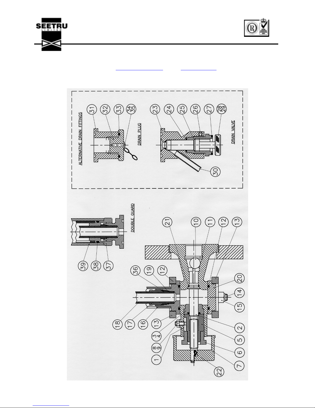
General Assembly – Figure 1
Item Number Number Off
per Unit
Description
1 1 Valve Body
2 1 Spindle
3 1 ‘O’ Ring
4 1 Gland
5 1 Spindle Nut
6 1 Gland Nut
7 1 Handwheel
8 1 Set Screw
9 1 Locknut
10 1 Ball
11 1 Retaining Clip
12 2 ‘O’ Ring
13 2 Clamp
14 2 Bolt
15 2 Nut
16 1 Inner Guard Tube
17 1 Tube Nut
18 1 Sight Tube
19 1 ‘O’ Ring
20 1 Blanking Plate
21 1 ‘O’ Ring
22 1 Knob Clip
23 1 Drain Valve Body
24 1 ‘O’ Ring
25 1 Sealing Nut
26 1 Set Screw
27 1 Retaining Clip
28 1 ‘O’ Ring
29 1 Plunger
30 1 Drain Tube
31 1 Body – Drain Plug
32 1 Plug
33 1 ‘O’ Ring
34 1 Drive Screw
35 1 Chain
36 1 Gland Bush
37 1 Gland Nut
38 1 ‘O’ Ring
39 1 Outer Guard Tube
Page 8
CPI TUBULAR GAUGE G23
INSTALLATION, OPERATING &
MAINTENANCE INSTRUCTIONS
SEETRU LIMITED
ALBION DOCKSIDE WORKS, HANOVER PLACE, BRISTOL BS1 6UT. ENGLAND
TEL. 0117 9279 204. FAX 0117 929 8193.
EMAIL: [email protected]
WEB: www.seetru.com
8
Figure 1
 Loading...