

Seeley LCQ, LCS, LCQI, CPQ, TBS Installation Manual
...
INSTALLATION MANUAL
LCQ / LCS / LCQI / BMQ / CPQ
TBS / TBQI / TBSI / TBQ
Evaporative Cooler
Original English Instructions
Original English Instructions

i |
INTERNA
TIONAL
TABLE OF CONTENTS
SAFETY 1
QUICK GUIDE 2
COOLER LOCATION 4
REMOVING THE VENTURI 4
REMOVING THE TRANSITION 4
PREPARING THE DROPPER 5
MOUNTING THE DROPPER 5
SECURING THE DROPPER & TRANSITION 5
AutoWinterseal™ 6
CONVEYING THE COOLER TO THE ROOF 6
MOUNTING THE COOLER 7
CABLE INSTALLATION 7
ELECTRICAL REQUIREMENTS 8
FIELD WIRING DIAGRAM 8
WATER REQUIREMENTS 8
INSTALLING THE FLOAT VALVE 9
INSTALLING THE INLET SOLENOID 9
MAINS WATER CONNECTION 9
INSTALLING THE DRAIN VALVE 10
INSTALLING THE WATER SENSOR 10
BLEED FUNNEL 10
INSTALLING THE VENTURI / FAN ASSEMBLY 11
ELECTRICAL CONNECTION 11
CONNECTING THE WATER PUMP 12
CONNECTING THE MAGIQTOUCH /MAGIQCOOL CONTROLLER® 12
MAGIQTOUCH CONTROLLER® DISPLAY INFORMATION 13
CHANGING THE WATER MANAGEMENT METHOD FOR THE MAGIQCOOL CONTROL 13
CHANGING THE SALINITY CONTROL METHOD FOR THE MAGIQCOOL CONTROL 13
SETTING THE WATER LEVEL 13
FAULT CODES INDICATED BY LED’s ON THE COOLER ELECTRONICS MODULE 14
COMMISSIONING THE COOLER 14
COMMISSIONING COMPLETION CHECKLIST 15
ADJUSTING COOLER SETTINGS 16
TROUBLE SHOOTING 17
WARNING! Failure to install and commission the product in compliance with these instructions, or failure to do
the job properly and competently, may void the customer’s warranty. Further, it could expose the Installer and/
or the Retailer to serious liability.

LCQ / LCS / LCQI / BMQ / CPQ / TBQ / TBS / TBQI / TBSI EVAPORATIVE COOLER INSTALLATION MANUAL | 1
SAFETY
Employer and Employee Responsibilities
The installation and maintenance of evaporative coolers at
height has the potential to create Occupational Health and
Safety issues for those involved. Installers are advised to
ensure they are familiar with the relevant State and Federal
legislation, such as Acts, Regulations, approved Codes of
Practice and Australian Standards, which offer practical
guidance on these health and safety issues. Compliance
with these regulations will require appropriate work practices,
equipment, training and qualications of workers.
Seeley International provides the following information as a
guide to contractors and employees to assist in minimising risk
whilst working at height.
WARNING - TO REDUCE THE RISK OF FIRE,
ELECTRIC SHOCK OR INJURY TO OTHER PERSONS,
OBSERVE THE FOLLOWING:
1. Use this unit only in the manner intended by the
manufacturer. If you have questions, contact the manufacturer.
2. Before servicing or cleaning the unit, switch power off at
service panel and lock the service disconnecting means to
prevent power from being switched on accidentally. When the
service disconnecting means cannot be locked, securely fasten
a prominent warning device, such as a tag to the service panel.
3. Installation work and electrical wiring must be done by
qualied person(s) in accordance with all applicable codes and
standards, including re-rated construction.
4. When cutting or drilling into walls or ceilings, do not damage
electrical wiring and other hidden utilities.
5. Ducted fans must always be vented to the outdoors.
6. Do not use this fan with any solid-state speed control device.
7. New hose sets supplied with the appliance are to be used.
Old hose sets (from previous installations) shall not be used.
8. If the supply cord is damaged, it must be replaced by the
Manufacturer, its Service Agent or similarly qualied persons in
order to avoid a hazard.
Installer and Maintenance Contractors
– Risk Assessment
A risk assessment of all hazardous tasks is required under
legislation. A risk assessment is an essential element that
should be conducted before the commencement of work, to
identify and eliminate the risk of falls or to minimise these risks
by implementing control measures. There is no need for this to
be a complicated process, it is just is a matter of looking at the
job to be done and considering what action(s) are necessary so
the person doing the job does not injure themselves.
This should be considered in terms of:
• What are the chances of an incident happening?
• What could the possible consequence be?
• What can you do to reduce, or better still, completely
eliminate the risk?
Some points to consider:
• What is the best and safest access to the roof and working
areas?
• If a worker is alone, who knows they are there and if they get
into difculty, how can they summon help? (Call someone on
the ground? Mobile phone? etc.).
• What condition is the roof in? Should the trusses, underside
or surface be checked?
• Does the worker have appropriate foot wear?
(Flat sole jogger type is advisable).
• Are all power cables / extension leads safe and appropriately
rated?
• Are all ladders, tools and equipment in a suitable and good
condition?
• Where ladders are to be used, is there a rm, stable base for
them to stand on? Can they be tied or secured in some way
at the top? Is the top of the ladder clear of electricity supply
cables?
• Is there a roof anchor to attach a harness and lanyard to? If
so, instruction should be issued for the use of an approved
harness or only suitably trained people used.
• Are all tools and materials being used, prevented from
slipping and falling onto a person at ground level? Is the area
below the work area suitably protected to prevent persons
walking in this area?
• Does the work schedule take into account weather conditions,
allowing for work to be suspended in high winds, thunder
storms/lightning or other types of weather giving wet, slippery
surfaces?
• Is there an on-going safety check system of harnesses,
ropes, ladders and access/lifting equipment and where they
exist on roofs, anchor points before the commencement of
work?
• Is there a system which prevents employees from working
on roofs if they are unwell or under the inuence of drugs or
alcohol?
• Are there any special conditions to consider?
(Eg: excessive roof pitch, limited ground area, fragile roof,
electrical power lines, etc)
Other Important Requirements
• Never force parts to t because all parts are designed to t
together easily without undue force.
• Never drill holes in the tank of the cooler.
• Check the proposed cooler location, to ensure that it is
structurally capable of supporting the weight of the cooler, or
provide an adequate alternate load bearing structure.
• Ensure the installation complies with all local and national
regulations with regards to electrical, plumbing and bushre
construction requirements.
2 |
INTERNA
TIONAL
QUICK GUIDE
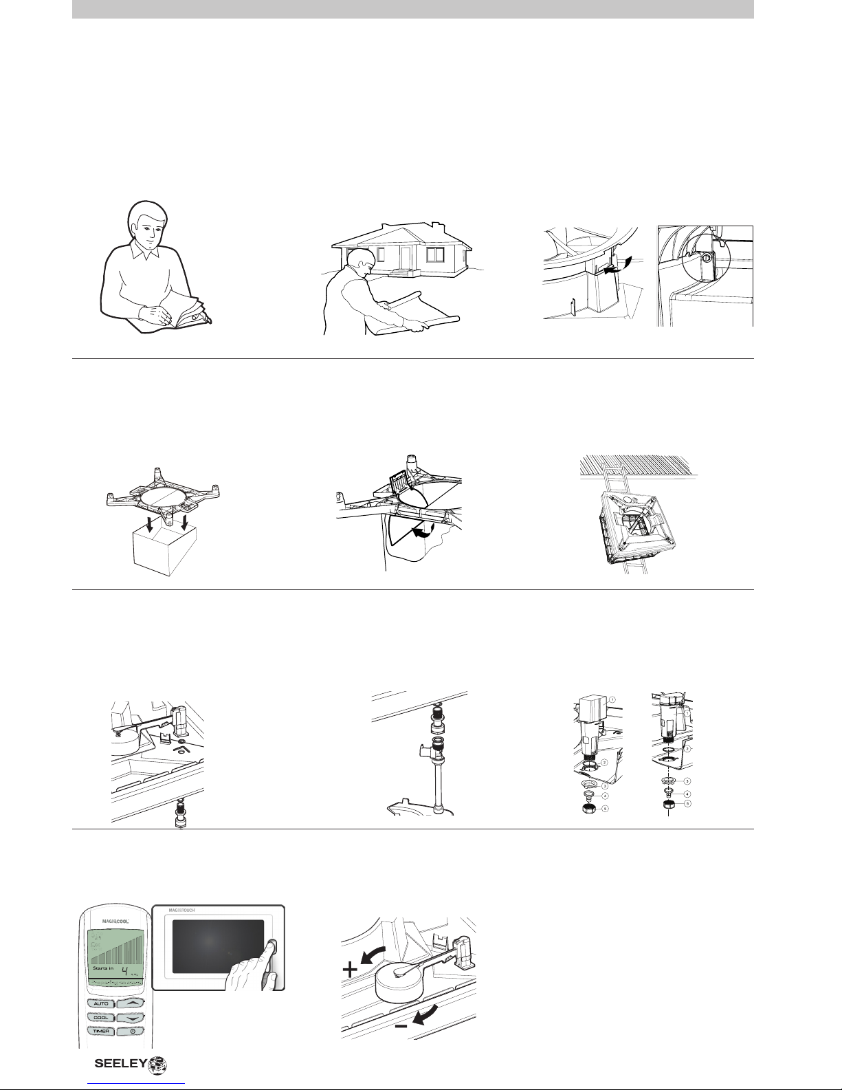
Step 1
SAFETY
Read & understand the safety section.
Step 7
SECURE DROPPER &
TRANSITION
Use the TEK screws provided. Break the
transport clips for the AutoWinterseal.
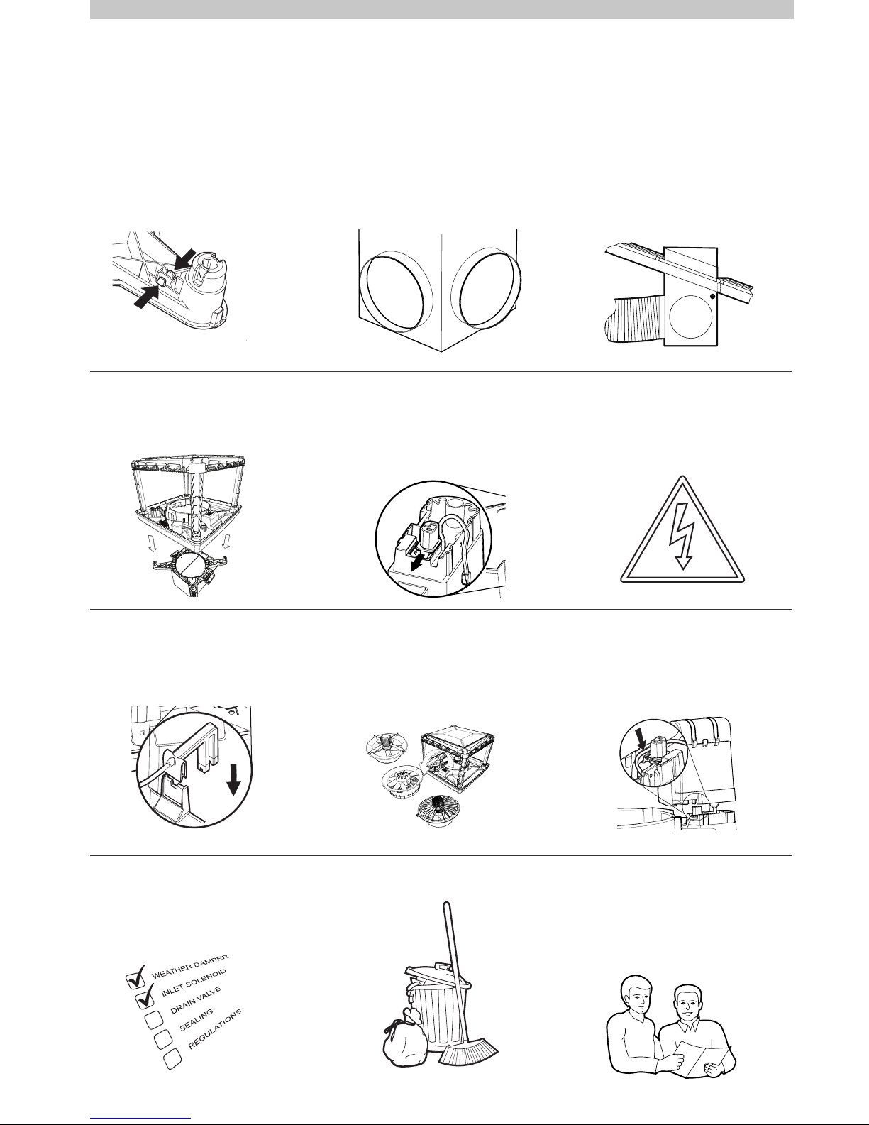
Step 14
INSTALL INLET SOLENOID
Use the supplied hose set and ttings.
Note the water ow direction marking on
the solenoid.
Step 20
SET THE WATER LEVEL
Turn on the mains water and adjust the
oat to allow water to ll to the required
level.
Step 21
COMMISSIONING THE COOLER
Switch the mains power on and test run
the cooler.
Step 2
COOLER LOCATION
Check cooler location. Consider
regulations. Discuss with customer.
Step 8
CHECK AutoWinterseal™
Check operation of the AutoWinterseal.
Ensure AutoWinterseal moves freely.
Step 15
INSTALL DRAIN VALVE
Never drain waste water directly onto the
roof. Be sure to use supplied ‘O’ Rings
and ttings.
Step 3
REMOVE VENTURI
Press the clip or remove the screws on
both sides of the venturi to release.
Step 9
CONVEY COOLER TO ROOF
Page 1
Page 8
Page 9
Page 4
Page 6
Page 10
Page 13
Page 6
Page 14
Page 4
Always use 2 persons to position the
cooler when handling manually.
Step 19
MOUNT AND CONNECT THE
CONTROLLER
Page 12
Step 13
INSTALL FLOAT VALVE
Assemble the oat valve to the cooler.
Ensure all washers and o-rings are in
place. No thread tape is required.
Page 9
LCQ / LCS / LCQI / BMQ / CPQ / TBQ / TBS / TBQI / TBSI EVAPORATIVE COOLER INSTALLATION MANUAL | 3
Step 22
FINAL CHECK
Complete the commissioning checklist at
the end of this document.
Step 23
CLEAN UP
Clean up the site!
Step 16
INSTALL WATER SENSOR
Ensure the clip is fully engaged.
Step 24
CUSTOMER HANDOVER
Show the customer how to operate the
cooler. Give them both the controller and
cooler owner’s manual.
Explain maintenance requirements.
Page 15 Page 15
Page 10
Page 16
Step 4
REMOVE TRANSITION
Press the clips inwards to release the
transition from the tank.
Step 10
MOUNT THE COOLER
Lower the cooler onto the transition.
Step 5
PREPARE THE DROPPER
Cut hole & t the grommet in the dropper
for power and control cables.
Step 11
CABLE INSTALLATION
Run the power and control cable
down the conduit and out through the
grommet.
Step 17
INSTALL VENTURI / FAN
Ensure the venturi is fully located into the
tank and the motor lead is not caught or
pinched.
Step 6
MOUNT DROPPER
Position, level and secure the dropper.
Flash the dropper to prevent water
ingress into the roof cavity.
Step 12
LOCAL REGULATIONS
Read and adhere to local electrical and
plumbing rules and regulations.
Step 18
ELECTRICAL CONNECTIONS
Connect the cooler components to the
electronics module. Plug the mains cable
into the electronics module.
Page 4
Page 7
Page 5
Page 11
Page 5
Page 8
Page 11
Page 7
QUICK GUIDE cont
CPQ/LCQ/LCS
TBQ/TBS
BMQ
LCQI/TBQI/TBSI
4 |
INTERNA
TIONAL
CPQ/LCQ/LCS
TBQ/TBS
BMQ
LCQI/TBQI/TBSI
COOLER LOCATION
Check proposed cooler location to ensure it is structurally
capable of supporting the weight of the cooler. If the roof is
structurally inadequate, provide an alternate load bearing
structure.
The ideal location for the cooler is in a central position on the
roof (away from sleeping areas and where people spend most
of their time) so that the duct runs are of approximately the
same length. Carefully consider neighbouring residences and
noise levels when locating the cooler, if necessary talk to the
customer and the neighbour before carrying out the installation.
Always locate the cooler where it will receive adequate fresh air
and not in a recess where it may be starved for air or where the
air is polluted.
Ensure location is a minimum of:
• 3m (10’) from a solid fuel heater ue,
• 1.5m (5’) from a gas ue,
• 5m (17’) from a sewer vent, and
• 600mm (2’) from a wall.
ILL1150-B
ILL2111-B
ILL1155-C
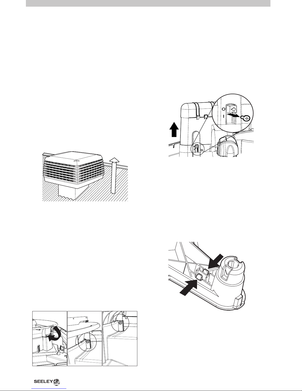
REMOVING THE VENTURI
Once the pad frames have been removed, detach the
venturi / fan assembly and the electronics module.
For LCQ/LCS/TBQ/TBS & CPQ models, disengage the two
venturi clips as shown. For LCQI/TBQI/TBSI & BMQ models,
remove the 2 screws securing the venturi to the tank.
X
REMOVING THE TRANSITION
• The cooler must be mounted at least 3m (10’), preferably
5m (17’), away from any TV antenna or antenna cables.
Make sure the cooler is not between the antenna and the
transmission tower that is providing the television signal to the
home.
Allow adequate access to and around the cooler for
maintenance. Provision must be made for access to electricity,
water supplies and drains.
Note! Do you need to discuss the installation of items like
safety anchor points with the customer?
Disconnect the electronics module from the tank by removing
the screw under the switch. The isolation switch cannot be
activated with this screw removed. Remove the pump and motor
cables from the plugs in the electronics module.
Note! Place the electronics module and the screw safely to
one side for later use. Do not re-t the electronics module, as
the motor plug will require connection to the underside of the
module when the venturi is retted into the cooler.
Lift the venturi and fan assembly out of the cooler, taking care of
the motor lead(s).
The venturi and fan assembly can be placed on to the ground
until the rest of the cooler has been installed on the dropper.
Turn the cooler onto its side to remove the transition.
There are clips in each of the four corners that will disengage
once the transition is given a rm pull.
If any of the corners are difcult to remove, do not use
excessive force. Gently squeeze the clips together and remove
the transition one corner at a time.
ILL1053-C
REMOVING THE VENTURI cont
 Loading...