

Seeley MobileMAX Series Conversion Manual
CONVERSION MANUAL
MobileMAX Assembly Instructions
For Kit 075594
(MobileMAX English)
Original English Instructions

TABLE OF CONTENTS
SAFETY
Warnings 3
Installer and Maintenance Contractors – Risk Assessment 3
Some Points to Consider 3
Other Important Requirements 3
KIT CONTENTS 4
MobileMAX Conversion Kit 4
CONVERSION INSTRUCTIONS 5
Packing List 5
Additional Items Required to Assemble the Kit 5
Modifying the Cooler 5
Removal Instructions 5
Modications to the Cooler 6
Service Cord Fitment 7
Assembly of Tank Kit Components 7
Assembly of Cooler to Tank 8
Front Grille Assembly 9
Mounting the Controls 10
Wiring the Cooler Controls 10
Wiring the Mains Power 11
COMMISSIONING THE COOLER 12
Fault Codes 12
Operating Adjustments 13
Setting the Motor Current 13
Pulley Sheave Adjustment 13
Belt Tension 13
Setting Water Level 14
Checking Water Level - Sight Glass 14
Testing the Cooler 14
Final Clean-Up 14
Labelling the Cooler 14
DRILLING TEMPLATE INFORMATION 15
WARNING: Failure to install and commission the product in compliance with these instructions,
or failure to do the job properly and competently, may void the customer’s warranty.
Further, it could expose the Installer and/or the Retailer to serious liability.
2 |

SAFETY
WARNING - TO REDUCE THE RISK OF FIRE, ELECTRIC
SHOCK OR INJURY TO OTHER PERSONS, OBSERVE THE
FOLLOWING:
1. Use this unit only in the manner intended by the
manufacturer. If you have questions, contact the
manufacturer.
2. Before servicing or cleaning the unit, switch power o
at service panel and lock the service disconnecting
means to prevent power from being switched on
accidentally. When the service disconnecting means
cannot be locked, securely fasten a prominent
warning device, such as a tag to the service panel.
3. Installation work and electrical wiring must be
done by qualied person(s) in accordance with all
applicable codes and standards, including re-rated
construction.
4. When cutting or drilling into walls or ceilings, do not
damage electrical wiring and other hidden utilities.
5. Ducted fans must always be vented to the outdoors.
6. Do not use this fan with any solid-state speed control
device.
7. If the supply cord is damaged, it must be replaced
by the Manufacturer, its Service Agent or similarly
qualied persons in order to avoid a hazard.
INSTALLER AND MAINTENANCE CONTRACTORS
– RISK ASSESSMENT
A risk assessment of all hazardous tasks is required
under legislation. A risk assessment is an essential
element that should be conducted before the
commencement of work, to identify and eliminate the risk
of falls or to minimise these risks by implementing control
measures. There is no need for this to be a complicated
process, it is just is a matter of looking at the job to be
done and considering what action(s) are necessary so
the person doing the job does not injure themselves.
This should be considered in terms of:
• What are the chances of an incident happening?
• What could the possible consequence be?
• What can you do to reduce, or better still, completely
eliminate the risk?
Some points to consider:
• If a worker is alone, who knows they are there and if
they get into diculty, how can they summon help?
(Mobile phone? etc.).
• Does the worker have appropriate foot wear?
• Are all power cables / extension leads safe and
appropriately rated?
• Are all tools and equipment in a suitable and good
condition?
Other Important Requirements
• Never force parts to t because all parts are designed
to t together easily without undue force.
• Ensure the installation complies with all local and
national regulations with regards to electrical and
plumbing requirements.
MOBILEMAX ASSEMBLY MANUAL | 3
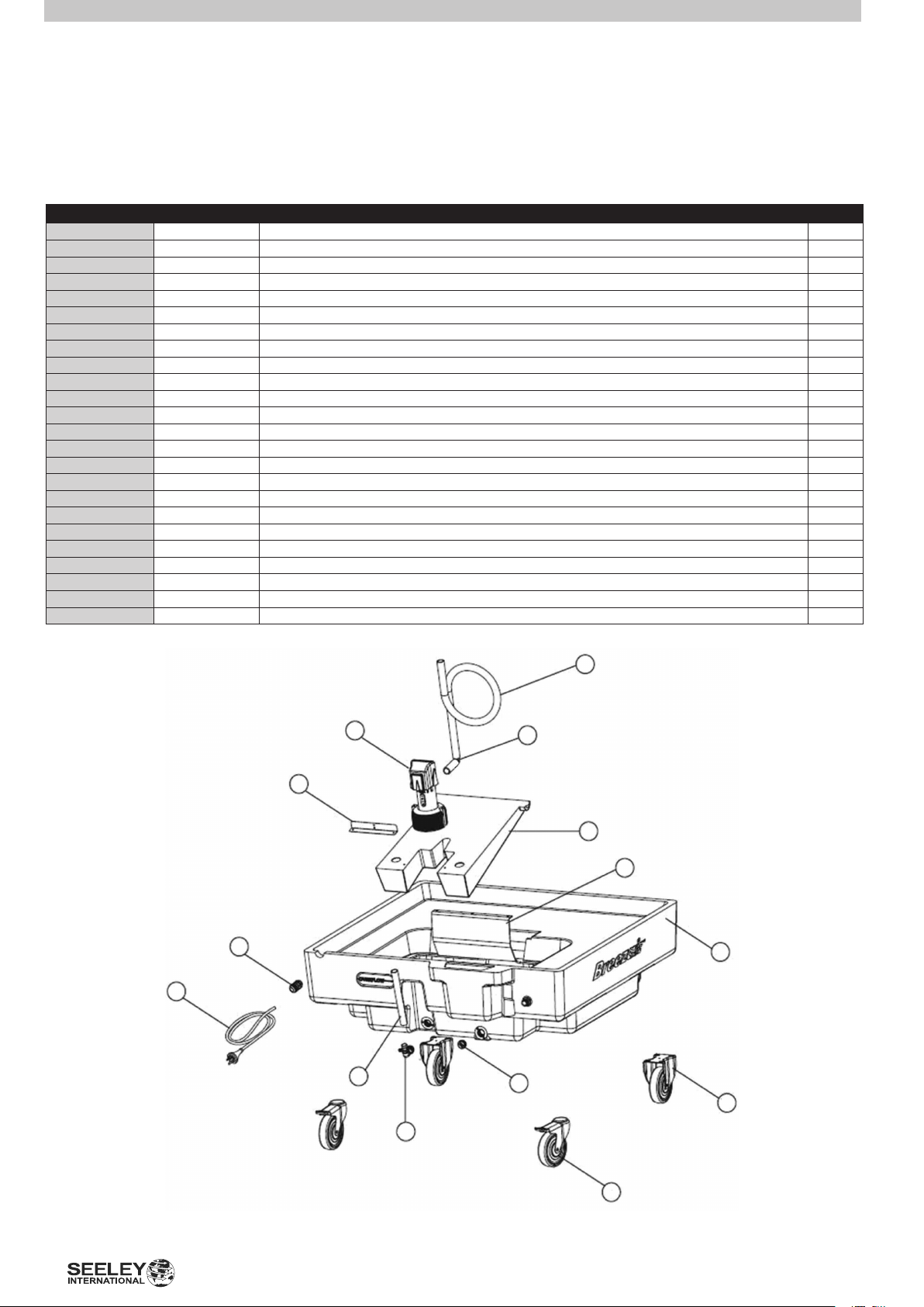
KIT CONTENTS
MOBILEMAX CONVERSION KIT
Contents
Item Part No. Description QTY
1 638607 Mobile Tank 1
2 638591 Float for Mobile Tank Pump 1
Not Shown 638737 Grille Kit 1
3 628950 Pump Bracket 1
4 095806 Tornado Pump 1
5 814841 Pump Hose 19mm (1.5m length) 1
6 MIS001 Pump Elbow 1
7 855035 Castor Wheel xed (tted to tank) 2
8 855042 Castor Wheel swivel (tted to tank) 2
9 803913 Mains Lead 6.0m 1
10 823812 Filling Bae 1
11 MIS143/853963 Water Level Sight Tube and Backing Sticker 1
12 630854 Sight Tube Elbow 1
13 608266 Water Inlet Brass Fitting 1/2” 1
14 630878 Drain Cap 1
Not Shown 862873 Communications Lead 1.5m 1
Not Shown PB814 Enclosure 1
Not Shown GH-229 Terminal Strip (3 positions) 1
Not Shown 631196 Cable Glands 16mm for Enclosure 2
Not Shown PZ364 Cable Gland 20mm for Switch Panel Control 1
Not Shown 823614 Cord Hook Cleats 2
Not Shown various Brackets, Screws, Rivets, Cable Ties and Fasteners for Conversion Assembly -
Not Shown various Brass and Poly plumbing ttings for water inlet and pump plumbing -
Not Shown 837697 Conversion Instruction Booklet 1
5
4
6
3
2
10
13
1
9
11
14
7
4 |
12
8
ILL1504-A
CONVERSION INSTRUCTIONS
PACKING LIST
This kit contains the following components:
• a 100 litre tank with wheels tted,
• a oating platform for the pump, with pump bracket
tted.
• a replacement hose assembly
• cord storage hooks, cord restraint glands and
fasteners,
• a grille outlet and a grille frame and fasteners
• pop rivets and fasteners.
• cable ties.
• 1/2” brass nipple and lock nut.
• Mains lead 3 pin 13 amp x 6m (t plug to suit
location)
• Communications Lead 6 Pin 1.5m CPMD to Switch
Plate Control
• Cable Gland 20mm to seal the 1.5m communications
lead hole drilled in the cooler
• Enclosure, Cable Glands 16mm, Terminal Strip and
mounting screws for connection of eld wiring mains
power to an IEC plugged cable to t into the CPMD.
• Drilling and cutout Template
Unpack the kit to ensure it contains the above
components.
MODIFYING THE COOLER
The cooler requires some modication prior to tting to
the MobileMAX Tank.
Some components will be removed and set aside for
later tment to the MobileMAX Tank while others will be
discarded.
REMOVAL INSTRUCTIONS
WARNING: ELECTRICAL WORK MUST ALWAYS BE
CARRIED OUT BY A QUALIFIED ELECTRICAL WORKER
Ensure that the cooler cannot be turned on whilst
work is being carried out.
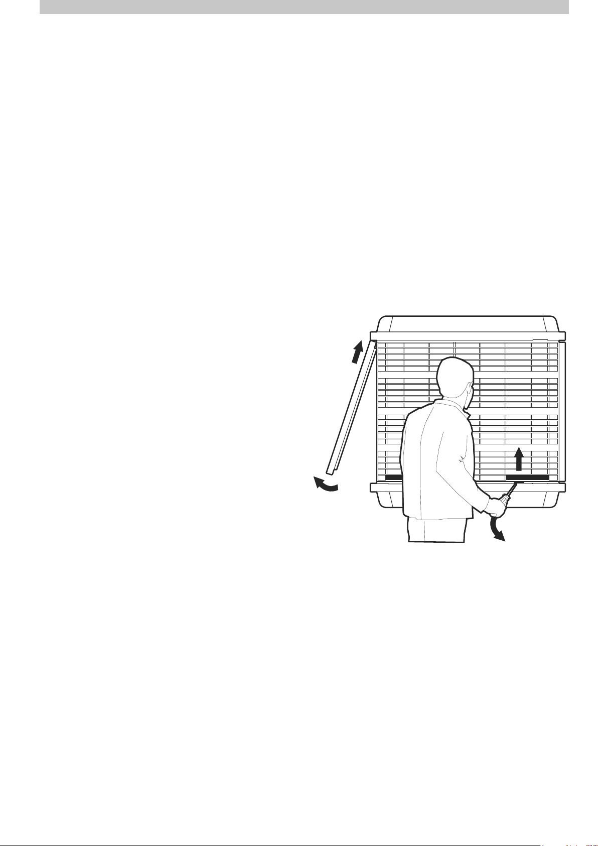
Remove all pads (side panels) from cooler and put them
safely aside allowing access to the inside of the cooler.
Additional items required to assemble the kit include;
• an electric drill,
• an electric jig saw or alternatively a narrow bladed
hand saw,
• a sharp knife,
• a philips head screwdriver,
• a pop-rivet gun,
• sandpaper,
• a tape measure, ruler and marker pen.
• a vacuum cleaner,
• a bucket of soapy water and clean loth,
• masking or packing tape,
• 20mm (3/4”) spade drill bit
• 25mm (1”) spade drill bit
• 16mm (5/8”) spade drill bit (Australia, South Africa
and Europe)
• 3mm (1/8”) drill bit
• 5mm (3/16”) drill bit
• Teon tape or approved sealing compound.
• scissors or a sharp blade knife,
ILL725-A
Remove packaged components located in the fan area
and set aside for later use.
Remove the oat valve by undoing the threaded in-line
connector.
Set the oat assembly aside for later use.
Remove the plastic washer and “O”ring from inline
connector.
Discard the plastic inline connector only.
MOBILEMAX ASSEMBLY MANUAL | 5
 Loading...