

Seeley MCHV81D14, MBHV35D1S, MBHV45D1S, MBHV71D1S, MCHV73D13 Owner's Manual
...
OWNER’S MANUAL
MULTI CASSETTE
(English) (MBHVD1S SERIES)
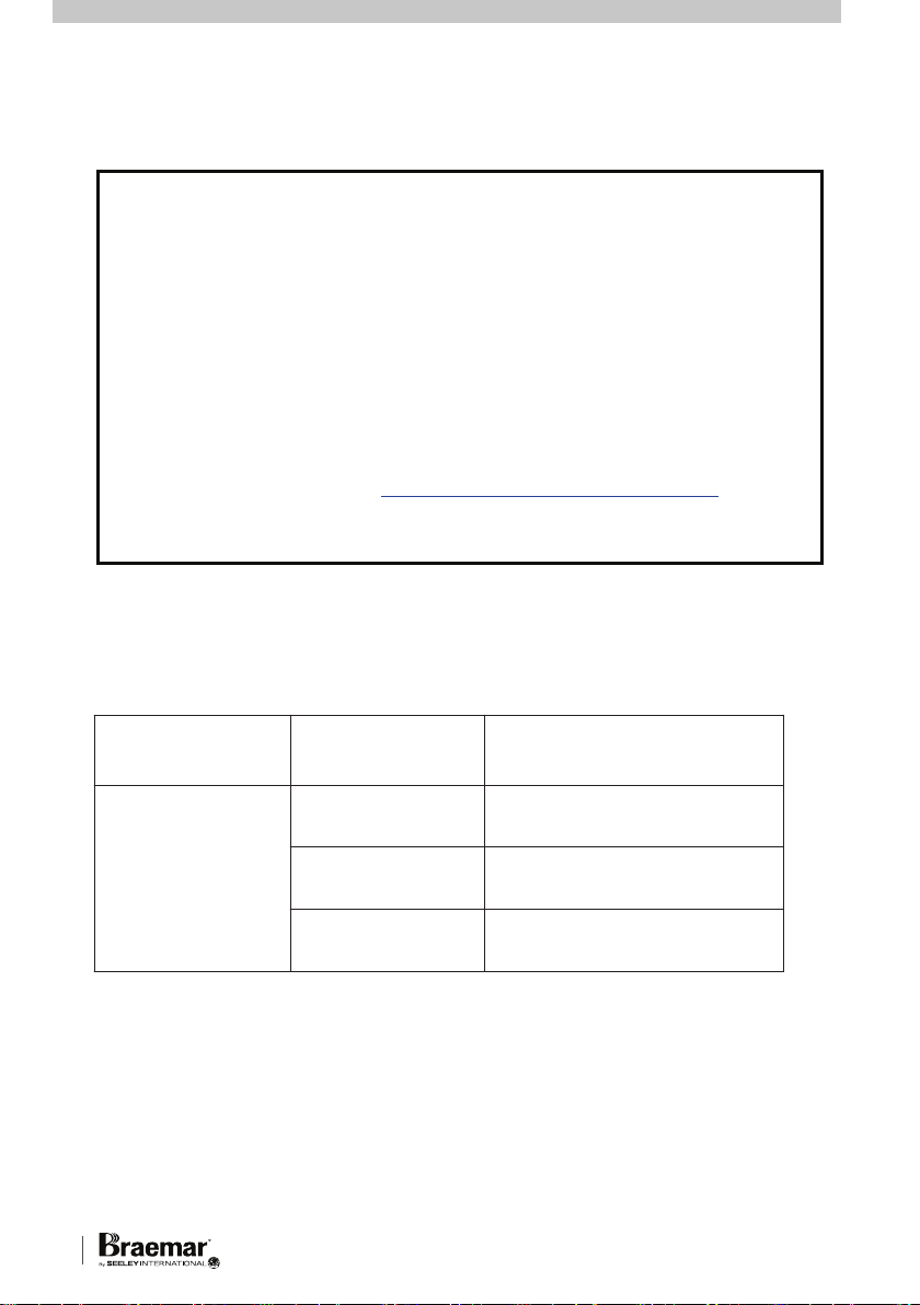
IMPORTANT
As with any product that has moving parts or is subject to wear and tear, it is
VERY IMPORTANT
serviced. Accordingly, it is a condition of warranty cover for your air conditioner
that you comply with all of the maintenance and service requirements set out
in this Manual. Compliance with these requirements will prolong the life of your
air conditioner. Further, it is also a condition of warranty cover that the
Maintenance Schedule in the Manual is filled out (by signing and dating it in
the places indicated) when the item is completed.
OUT THE REQUIRED MAINTENANCE AND SERVICING, AND ANY
FAILURE TO FILL OUT THE MAINTENANCE SCHEDULE, WILL VERY
LIKELY VOID YOUR WARRANTY.
(For complete warranty terms, refer to the separate Warranty Booklet sold with
the product. Alternatively, visit
download the terms.
that you maintain your air conditioner and have it regularly
ANY FAILURE TO CARRY
www.seeleyinternational.com/warranty
to
Warranty terms are subject to property access and industry safety standards.)
OUTDOOR
MODELS
MCHV54D12
MCHV73D13
MCHV81D14
MCHV10D14
MCHV11D15
INDOOR
CAPACITY COOL / HEAT
MODEL
MBHV35D1S
MBHV45D1S
MBHV71D1S
MBHVD1S Series Multi Cassette i
3.5 kW / 4.0 kW
4.5 kW / 5.0 kW
7.1 kW / 8.0 kW

MAIN COMPONENTS.........................................................................................2
INTRODUCTION & SAFETY ..............................................................................3
OPERATION
WIRED CONTROLLER..................................................................................4
CONTROLLER LAYOUT ..........................................................................4
LCD ICONS............................................................................................4-5
BUTTON FUNCTIONS ..........................................................................5-6
ON/OFF .....................................................................................................6
MODE SETTING .......................................................................................7
TEMPERATURE SETTING .......................................................................7
FAN SETTING...........................................................................................7
TIMER SETTING.......................................................................................8
SLEEP SETTING ......................................................................................9
TURBO FUNCTION SETTING................................................................10
BLOW FUNCTION SETTING..................................................................11
LOCK FUNCTION...................................................................................12
MEMORY FUNCTION.............................................................................12
REMOTE CONTROLLER ............................................................................12
CHANGING BATTERIES ........................................................................13
CONTROLLER LAYOUT ........................................................................13
ON/OFF ...................................................................................................14
MODE......................................................................................................14
FAN SPEED ............................................................................................14
CLOCK....................................................................................................14
TEMP.......................................................................................................14
+/- BUTTONS..........................................................................................14
X-FAN.................................................................................................14-15
TURBO....................................................................................................15
LIGHT......................................................................................................15
TIMER SETTING.....................................................................................15
I FEEL .....................................................................................................15
SLEEP.....................................................................................................15
ERROR DISPLAY ...................................................................................16-18
MAINTENANCE & SERVICE............................................................................19
MAINTENANCE SCHEDULE ...........................................................................20
OPERATION TIPS.............................................................................................21
TROUBLESHOOTING .................................................................................22-23
NOTES .........................................................................................................24-25
SEELEY INTERNATIONAL – OWNER’S MANUAL 1
CONTENTS
CONTENTS
MAIN COMPONENTS.........................................................................................2
INTRODUCTION & SAFETY ..............................................................................3
OPERATION
WIRED CONTROLLER..................................................................................4
CONTROLLER LAYOUT ..........................................................................4
LCD ICONS............................................................................................4-5
BUTTON FUNCTIONS ..........................................................................5-6
ON/OFF .....................................................................................................6
MODE SETTING .......................................................................................7
TEMPERATURE SETTING .......................................................................7
FAN SETTING...........................................................................................7
TIMER SETTING.......................................................................................8
SLEEP SETTING ......................................................................................9
TURBO FUNCTION SETTING................................................................10
BLOW FUNCTION SETTING..................................................................11
LOCK FUNCTION...................................................................................12
MEMORY FUNCTION.............................................................................12
REMOTE CONTROLLER ............................................................................12
CHANGING BATTERIES ........................................................................13
CONTROLLER LAYOUT ........................................................................13
ON/OFF ...................................................................................................14
MODE......................................................................................................14
FAN SPEED ............................................................................................14
CLOCK....................................................................................................14
TEMP.......................................................................................................14
+/- BUTTONS..........................................................................................14
X-FAN.................................................................................................14-15
TURBO....................................................................................................15
LIGHT......................................................................................................15
TIMER SETTING.....................................................................................15
I FEEL .....................................................................................................15
SLEEP.....................................................................................................15
ERROR DISPLAY ...................................................................................16-18
MAINTENANCE & SERVICE............................................................................19
MAINTENANCE SCHEDULE ...........................................................................20
OPERATION TIPS.............................................................................................21
TROUBLESHOOTING .................................................................................22-23
NOTES .........................................................................................................24-25
SEELEY INTERNATIONAL - OWNER’S MANUAL
1
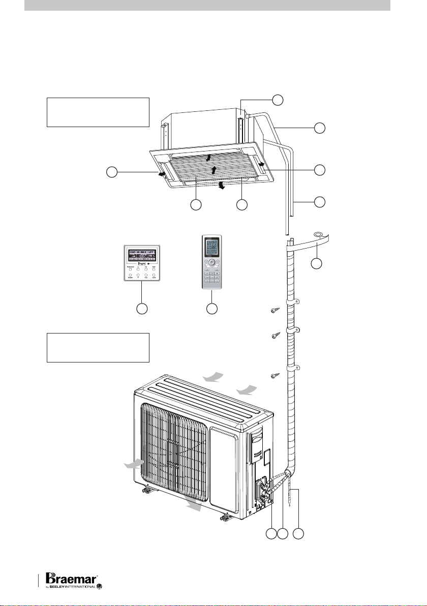
MAIN COMPONENTS
TYPICAL INSTALLATION / DIAGRAM OF KEY COMPONENTS
INDOOR UNIT
4
5
1
OUTDOOR UNIT
2 3
8 9
Air inlet
6
7
10
1. Air outlet vent
2. Air filter, purifier
(in air inlet grille)
3. Air inlet grille
4. Drainage equipment
5. Drainage pipe
6. Guide louvre (in air
outlet vent)
7. Connecting pipes
8. Wired Controller
9. Remote controller
(optional)
10. Binding tape
11. Liquid Pipe
12. Gas Pipe
13. Drain Pipe
Air outlet
131211
MBHVD1S Series Multi Cassette 2

when the Braemar
is used. Note: the
manufacturer recommends that low
level return air grilles are installed.
IMPORTANT!
THE AUSTRALIAN GREENHOUSE
OFFICE HAS ISSUED VARIOUS
REGULATIONS ON THE USE AND
DISPOSAL OF REFRIGERANTS IN
THE UNIT. FAILURE TO FOLLOW
THESE REGULATIONS MAY HARM
THE ENVIRONMENT AND COULD
LEAD TO THE IMPOSITION OF
SUBSTANTIAL FINES.
WHERE SPECIFIED, ONLY
QUALIFIED AND LICENSED
TECHNICIANS SHOULD PERFORM
WORK ON THIS UNIT, FAILING
WHICH THE WARRANTY ON THE
UNIT WILL BE VOID.
WARNING! This appliance is not
intended for use by persons (including
children) with reduced physical,
sensory or mental capabilities, or lack
of experience and knowledge, unless
they have been given supervision or
instruction concerning use of the
appliance by a person responsible for
their safety.
Children should be supervised to
ensure that they do not play with the
appliance.
If the supply cord is damaged, it must
be replaced by the manufacturer, its
service agent or similarly qualified
persons in order to avoid a hazard.
Ducted Inverter Air
Conditioning Unit
SEELEY INTERNATIONAL – OWNER’S MANUAL 3
INTRODUCTION & SAFETY
Congratulations on purchasing a new
Braemar Air Conditioner!
Please keep this Manual and the
Warranty Booklet in a safe place,
along with the original purchase
documents, plus all relevant
certificates of compliance relating to
the installation work performed. Please
register the Warranty straight away, by
following the steps set out in the
Warranty Booklet.
The installer must read the Installation
Manual before installing the Braemar
Ducted Inverter Air Conditioning Unit.
The home owner/user should read the
Owner's Manual before operating the
Unit.
To ensure the warranty on the Unit is
continued and valid, the Unit must be
checked and serviced by a Qualified
Licensed Technician as per the
requirements in the Maintenance &
Service section and the Maintenance
Schedule. This will also prolong the life
of your air conditioner.
The home owner/user should regularly
check the Air Inlet side of the Outdoor
unit (see the diagram on page 2) to
ensure grass, leaf and other matter are
not drawn into or onto the Inlet side of
the Outdoor unit. Restriction to the air
flow across the coil will reduce the
system's capacity, and result in high
operation pressures and excessive
operating costs.
A return air filter MUST be installed by
the installer at the return air grille. The
air filter should be inspected and
cleaned at least every two weeks
when the Braemar Cassette Air
is used. Note: the
manufacturer recommends that low
level return air grilles are installed.
IMPORTANT!
THE AUSTRALIAN GREENHOUSE
OFFICE HAS ISSUED VARIOUS
REGULATIONS ON THE USE AND
DISPOSAL OF REFRIGERANTS IN
THE UNIT. FAILURE TO FOLLOW
THESE REGULATIONS MAY HARM
THE ENVIRONMENT AND COULD
LEAD TO THE IMPOSITION OF
SUBSTANTIAL FINES.
WHERE SPECIFIED, ONLY
QUALIFIED AND LICENSED
TECHNICIANS SHOULD PERFORM
WORK ON THIS UNIT, FAILING
WHICH THE WARRANTY ON THE
UNIT WILL BE VOID.
WARNING! This appliance is not
intended for use by persons (including
children) with reduced physical,
sensory or mental capabilities, or lack
of experience and knowledge, unless
they have been given supervision or
instruction concerning use of the
appliance by a person responsible for
their safety.
Children should be supervised to
ensure that they do not play with the
appliance.
If the supply cord is damaged, it must
be replaced by the manufacturer, its
service agent or similarly qualified
persons in order to avoid a hazard.
Conditioning Unit
INTRODUCTION & SAFETY
Congratulations on purchasing a new
Braemar Air Conditioner!
Please keep this Manual and the
Warranty Booklet in a safe place,
along with the original purchase
documents, plus all relevant
certificates of compliance relating to
the installation work performed. Please
register the Warranty straight away, by
following the steps set out in the
Warranty Booklet.
The installer must read the Installation
Manual before installing the Braemar
Ducted Inverter Air Conditioning Unit.
The home owner/user should read the
Owner's Manual before operating the
Unit.
To ensure the warranty on the Unit is
continued and valid, the Unit must be
checked and serviced by a Qualified
Licensed Technician as per the
requirements in the Maintenance &
Service section and the Maintenance
Schedule. This will also prolong the life
of your air conditioner.
The home owner/user should regularly
check the Air Inlet side of the Outdoor
unit (see the diagram on page 2) to
ensure grass, leaf and other matter are
not drawn into or onto the Inlet side of
the Outdoor unit. Restriction to the air
flow across the coil will reduce the
system's capacity, and result in high
operation pressures and excessive
operating costs.
A return air filter MUST be installed by
the installer at the return air grille. The
air filter should be inspected and
cleaned at least every two weeks
when the Braemar
is used. Note: the
manufacturer recommends that low
level return air grilles are installed.
IMPORTANT!
THE AUSTRALIAN GREENHOUSE
OFFICE HAS ISSUED VARIOUS
REGULATIONS ON THE USE AND
DISPOSAL OF REFRIGERANTS IN
THE UNIT. FAILURE TO FOLLOW
THESE REGULATIONS MAY HARM
THE ENVIRONMENT AND COULD
LEAD TO THE IMPOSITION OF
SUBSTANTIAL FINES.
WHERE SPECIFIED, ONLY
QUALIFIED AND LICENSED
TECHNICIANS SHOULD PERFORM
WORK ON THIS UNIT, FAILING
WHICH THE WARRANTY ON THE
UNIT WILL BE VOID.
WARNING! This appliance is not
intended for use by persons (including
children) with reduced physical,
sensory or mental capabilities, or lack
of experience and knowledge, unless
they have been given supervision or
instruction concerning use of the
appliance by a person responsible for
their safety.
Children should be supervised to
ensure that they do not play with the
appliance.
If the supply cord is damaged, it must
be replaced by the manufacturer, its
service agent or similarly qualified
persons in order to avoid a hazard.
Ducted Inverter Air
Conditioning Unit
SEELEY INTERNATIONAL – OWNER’S MANUAL 3
INTRODUCTION & SAFETY
Congratulations on purchasing a new
Braemar Air Conditioner!
Please keep this Manual and the
Warranty Booklet in a safe place,
along with the original purchase
documents, plus all relevant
certificates of compliance relating to
the installation work performed. Please
register the Warranty straight away, by
following the steps set out in the
Warranty Booklet.
The installer must read the Installation
Manual before installing the Braemar
Ducted Inverter Air Conditioning Unit.
The home owner/user should read the
Owner's Manual before operating the
Unit.
To ensure the warranty on the Unit is
continued and valid, the Unit must be
checked and serviced by a Qualified
Licensed Technician as per the
requirements in the Maintenance &
Service section and the Maintenance
Schedule. This will also prolong the life
of your air conditioner.
The home owner/user should regularly
check the Air Inlet side of the Outdoor
unit (see the diagram on page 2) to
ensure grass, leaf and other matter are
not drawn into or onto the Inlet side of
the Outdoor unit. Restriction to the air
flow across the coil will reduce the
system's capacity, and result in high
operation pressures and excessive
operating costs.
A return air filter MUST be installed by
the installer at the return air grille. The
air filter should be inspected and
cleaned at least every two weeks
when the Braemar
is used. Note: the
manufacturer recommends that low
level return air grilles are installed.
IMPORTANT!
THE AUSTRALIAN GREENHOUSE
OFFICE HAS ISSUED VARIOUS
REGULATIONS ON THE USE AND
DISPOSAL OF REFRIGERANTS IN
THE UNIT. FAILURE TO FOLLOW
THESE REGULATIONS MAY HARM
THE ENVIRONMENT AND COULD
LEAD TO THE IMPOSITION OF
SUBSTANTIAL FINES.
WHERE SPECIFIED, ONLY
QUALIFIED AND LICENSED
TECHNICIANS SHOULD PERFORM
WORK ON THIS UNIT, FAILING
WHICH THE WARRANTY ON THE
UNIT WILL BE VOID.
WARNING! This appliance is not
intended for use by persons (including
children) with reduced physical,
sensory or mental capabilities, or lack
of experience and knowledge, unless
they have been given supervision or
instruction concerning use of the
appliance by a person responsible for
their safety.
Children should be supervised to
ensure that they do not play with the
appliance.
If the supply cord is damaged, it must
be replaced by the manufacturer, its
service agent or similarly qualified
persons in order to avoid a hazard.
Ducted Inverter Air
Conditioning Unit
SEELEY INTERNATIONAL – OWNER’S MANUAL 3
INTRODUCTION & SAFETY
Congratulations on purchasing a new
Braemar Air Conditioner!
Please keep this Manual and the
Warranty Booklet in a safe place,
along with the original purchase
documents, plus all relevant
certificates of compliance relating to
the installation work performed. Please
register the Warranty straight away, by
following the steps set out in the
Warranty Booklet.
The installer must read the Installation
Manual before installing the Braemar
Cassette Inverter Air Conditioning Unit.
The home owner/user should read the
Owner's Manual before operating the
Unit.
To ensure the warranty on the Unit is
continued and valid, the Unit must be
checked and serviced by a Qualified
Licensed Technician as per the
requirements in the Maintenance &
Service section and the Maintenance
Schedule. This will also prolong the life
of your air conditioner.
The home owner/user should regularly
check the Air Inlet side of the Outdoor
unit (see the diagram on page 2) to
ensure grass, leaf and other matter are
not drawn into or onto the Inlet side of
the Outdoor unit. Restriction to the air
flow across the coil will reduce the
system's capacity, and result in high
operation pressures and excessive
operating costs.
A return air filter MUST be installed by
the installer at the return air grille. The
air filter should be inspected and
cleaned at least every two weeks
when the Braemar Cassette Air
Conditioning Unit
manufacturer recommends that low
level return air grilles are installed.
IMPORTANT!
THE AUSTRALIAN GREENHOUSE
OFFICE HAS ISSUED VARIOUS
REGULATIONS ON THE USE AND
DISPOSAL OF REFRIGERANTS IN
THE UNIT. FAILURE TO FOLLOW
THESE REGULATIONS MAY HARM
THE ENVIRONMENT AND COULD
LEAD TO THE IMPOSITION OF
SUBSTANTIAL FINES.
WHERE SPECIFIED, ONLY
QUALIFIED AND LICENSED
TECHNICIANS SHOULD PERFORM
WORK ON THIS UNIT, FAILING
WHICH THE WARRANTY ON THE
UNIT WILL BE VOID.
WARNING! This appliance is not
intended for use by persons (including
children) with reduced physical,
sensory or mental capabilities, or lack
of experience and knowledge, unless
they have been given supervision or
instruction concerning use of the
appliance by a person responsible for
their safety.
Children should be supervised to
ensure that they do not play with the
appliance.
If the supply cord is damaged, it must
be replaced by the manufacturer, its
service agent or similarly qualified
persons in order to avoid a hazard.
is used. Note: the
SEELEY INTERNATIONAL - OWNER’S MANUAL
3
OPERATION
Your Braemar
Conditioning Unit
Cassette Air
has been designed
and built with reliable, quality
components. To ensure many years of
trouble free, dependable service
please read the following pages very
carefully, and please ensure that you
follow all of the instructions.
WIRED CONTROLLER
Please follow the below cautionary
notes when using the wired controller:-
1. Do not install the wired controller in
a damp place or under direct sunlight.
2. Do not abuse, toss, or assemble/
disassemble the wired controller.
3. Do not operate the wired controller
with wet hands and never let any liquid
flow into it.
4. Do not install or remove the wired
controller by yourself. If necessary,
please contact a service agent.
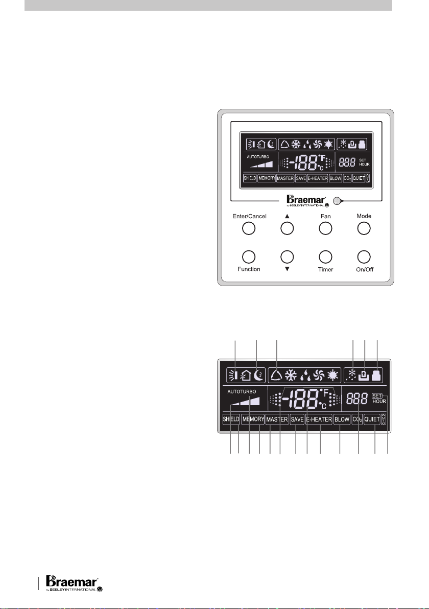
CONTROLLER LAYOUT
Appearance and LCD Icons
Wired Controller appearance
1
6532 4
5. This wired controller is applicable to
various kinds of air conditioners some specific functions unavailable to
the duct type air conditioners will be
covered in this manual.
6. Before operating the air conditioner,
please read this manual carefully and
keep it in a safe place for future
reference.
MBHVD1S Series Multi Cassette 4
7 8 9 10 1112 13 14 15 16 17 18 19
LCD Icon Layout
OPERATION cont.
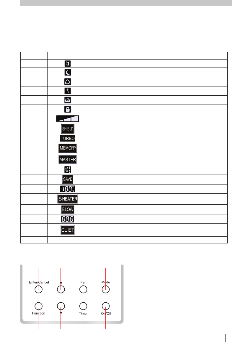
LCD ICONS
1
5
2
6
3
7
4
8
BUTTON FUNCTIONS
noitpircseDslobmyS.oN
1 Swing function (Not available on Multi Bulkhead Ducted units)
2 Sleep function
3 Operating modes for the Indoor unit (Auto, Cool, Dry, Fan and Heat)
4 Defrosting function for the Outdoor unit
5 Gate-control function (Not available on Multi Bulkhead Ducted units)
6 Lock function
7 High, middle, low or auto fan speed of the indoor unit
8
Shield functions (buttons, temperature, On/Off or Mode) is shielded
from the remote controller.
9 Turbo function
10
Memory function (The indoor unit resumes the original setting state
after power failure and then power recovery)
11
Master wired remote controller (Not available on Multi Bulkhead
Ducted units)
12 On status indicator
13
Energy-saving function (Not available on Multi Bulkhead Ducted units)
14 Ambient/preset temperature value
15
Electric auxiliary heating function (Not available on Multi Bulkhead
Ducted units)
16 Blow function
17 Timing value
18
Quiet function (two types: quiet and auto quiet)
(Not available on Multi Bulkhead Ducted units)
19 SET It will be displayed under the debugging mode.
SEELEY INTERNATIONAL – OWNER’S MANUAL 5
OPERATION cont.
LCD ICONS
No. Symbols Description
1
2
3
4
5
6
7
8
9
10
11
12
13
14 Ambient/preset temperature value
15
16
17
18
19 SET It will be displayed under the debugging mode.
Swing function (Not available on Multi Bulkhead Ducted units)
Sleep function
Operating modes for the Indoor unit (Auto, Cool, Dry, Fan and Heat)
Defrosting function for the Outdoor unit
Gate-control function (Not available on Multi Bulkhead Ducted units)
Lock function
High, middle, low or auto fan speed of the indoor unit
Shield functions (buttons, temperature, On/Off or Mode) is shielded
from the remote controller.
Turbo function
Memory function (The indoor unit resumes the original setting state
after power failure and then power recovery)
Master wired remote controller (Not available on Multi Bulkhead
Ducted units)
On status indicator
Energy-saving function (Not available on Multi Bulkhead Ducted units)
Electric auxiliary heating function (Not available on Multi Bulkhead
Ducted units)
Blow function
Timing value
Quiet function (two types: quiet and auto quiet)
(Not available on Multi Bulkhead Ducted units)
BUTTON FUNCTIONS
1
5
2
6
3
7
4
8
SEELEY INTERNATIONAL - OWNER’S MANUAL
5
OPERATION cont.
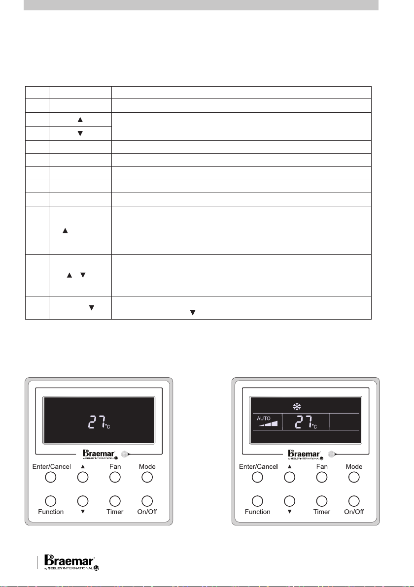
BUTTON FUNCTIONS cont.
No. Press Buttons Function
1 Enter/Cancel Function selection and cancellation.
2
6
3 Fan Setting of the high/middle/low/auto fan speed.
4 Mode Setting of the Cooling/Heating/Fan/Dry/Auto mode of the indoor unit.
5 Function Switchover among the functions of Turbo/Save/E-heater/Blow etc..
7 Timer Timer setting.
8 On/Off Turn on/off the indoor unit.
4+2
2+6
4+6 Mode+
+ Mode
+
• Running temperature setting of the indoor unit, range:16 - 30°C
• Timer setting, range:0.5-24 hr.
Press them for 5s under off state of the unit to Enter/Cancel the Memory
function (if memory is set, indoor unit after power failure and then power
recovery will resume the origina l setting state. If not, the indoor unit is
defaulte d to be off after power recovery. Memory off is de fault before
delivery).
Upon startup of the uni t without mal function or under off st ate of the
unit, press them at the same time for 5s to enter the lock state, in which
case any other buttons won’t respond.
Repress them for 5s to quit this state.
Under OFF state, the Celsius and Fahrenheit scales can be switched by
pressing “Mode” and “ ” for five seconds.
ON / OFF
Press the On/Off button to turn the unit on or off.
OFF State of the Unit
MBHVD1S Series Multi Cassette 6
ON State of the Unit
FAN SPEED SETTING
Press the Fan button to vary the
speeds as shown in the sequence
below.
Enter/Cancel
Fan Mode
Function
Timer
On/Off
AUTO
Low Middle
High
SEELEY INTERNATIONAL – OWNER’S MANUAL 7
Auto Cooling Dry Fan Heating
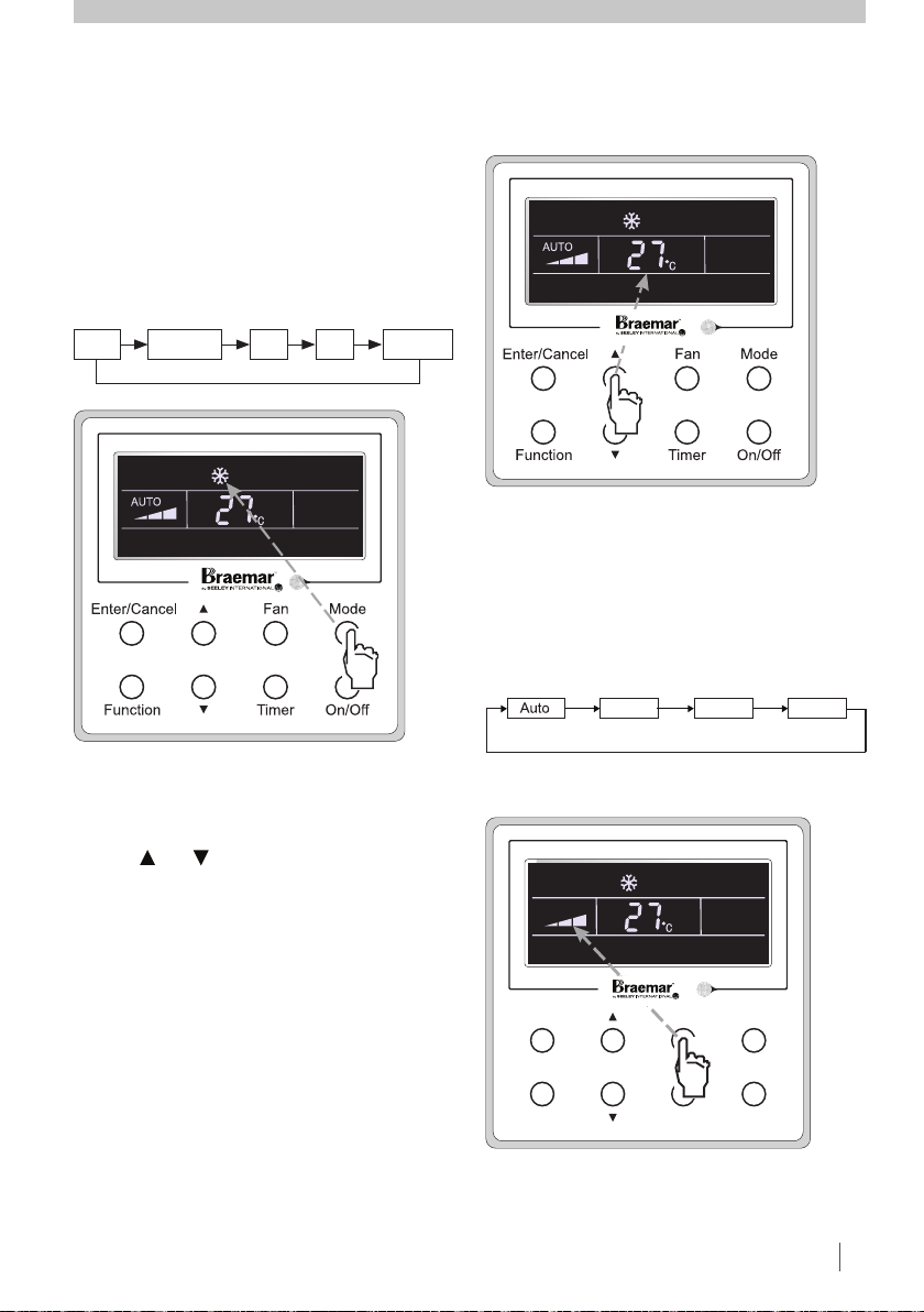
OPERATION cont.
MODE SETTING
TEMPERATURE SETTING
Under the ON state of the unit, press
the Mode button to switch the
operation modes as the sequence
shown below.
Press or button to increase or
decrease setting temperature when
the unit is on. Pressing either of them
continuously, temperature will be
increased or decreased by 1°C every
0.5s.
In Cooling, Dry, Fan and Heating
mode, temperature setting range is
16°C - 30°C.
In Auto mode, the setting temperature
is not adjustable.
FAN SPEED SETTING
Press the Fan button to vary the
speeds as shown in the sequence
below.
Enter/Cancel
Fan Mode
Function
Timer
On/Off
AUTO
Low Middle
High
Auto Cooling Dry Fan Heating
OPERATION cont.
MODE SETTING
TEMPERATURE SETTING
Under the ON state of the unit, press
the Mode button to switch the
operation modes as the sequence
shown below.
Press or button to increase or
decrease setting temperature when
the unit is on. Pressing either of them
continuously, temperature will be
increased or decreased by 1°C every
0.5s.
In Cooling, Dry, Fan and Heating
mode, temperature setting range is
16°C - 30°C.
In Auto mode, the setting temperature
is not adjustable.
FAN SPEED SETTING
Press the Fan button to vary the
speeds as shown in the sequence
below.
Enter/Cancel
Fan Mode
Function
Timer
On/Off
AUTO
Low Middle
High
SEELEY INTERNATIONAL – OWNER’S MANUAL 7
OPERATION cont.
MODE SETTING
Under the ON state of the unit, press
the Mode button to switch the
operation modes as the sequence
shown below.
Auto Cooling Dry Fan Heating
FAN SPEED SETTING
Press the Fan button to vary the
speeds as shown in the sequence
below.
Low Middle
High
TEMPERATURE SETTING
Press or button to increase or
decrease setting temperature when
the unit is on. Pressing either of them
continuously, temperature will be
increased or decreased by 1°C every
0.5s.
In Cooling, Dry, Fan and Heating
mode, temperature setting range is
16°C - 30°C.
In Auto mode, the setting temperature
is not adjustable.
AUTO
Fan Mode
Timer
On/Off
Enter/Cancel
SEELEY INTERNATIONAL - OWNER’S MANUAL
Function
7
 Loading...