

Seeley GDH Series Installation, Startup, Operation, Service & Maintenance Manual
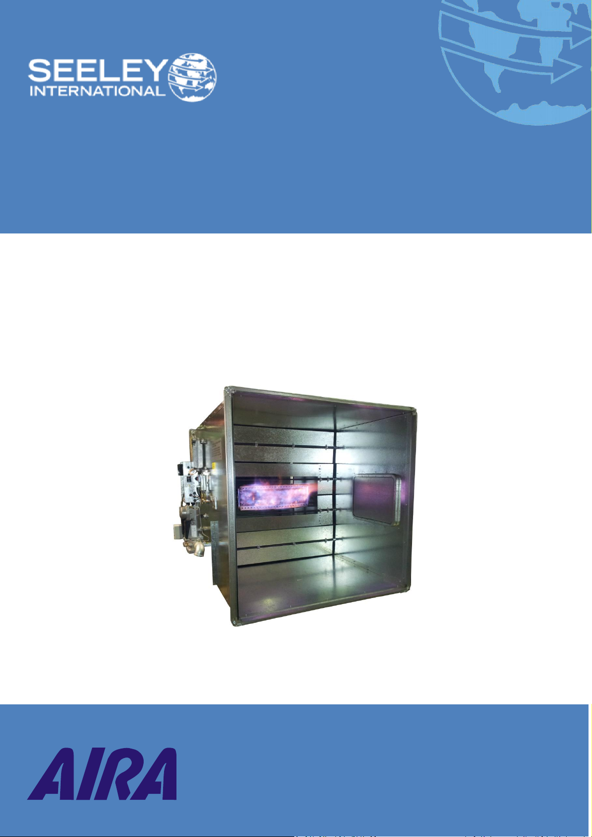
GDH Series Direct Fired Ducted Heater
Page 1 of 16
Installation, Startup, Operation,
Service & Maintenance Manual
GDH Series
Direct Fired Gas Heating

Table of Contents
GDH Series Direct Fired Ducted Heater
Page 2 of 16
Contents
GENERAL INFORMATION .....................................................................................................................3
About DGH & LU Units ..................................................................................................................................... 3
Standard Unit Details ....................................................................................................................................... 3
Extra Cost Options Available ............................................................................................................................ 3
Construction ..................................................................................................................................................... 4
Main Burner Assembly .................................................................................................................................. 4
Burner Control ............................................................................................................................................... 4
Valve Train .................................................................................................................................................... 4
Safety controls ............................................................................................................................................... 4
INSTALLATION INFORMATION ...............................................................................................................5
Basic Installation............................................................................................................................................... 5
Example Installation ......................................................................................................................................... 6
START UP ............................................................................................................ Error! Bookmark not defined.
OPERATING INSTRUCTIONS ..................................................................................................................9
TECHNICAL INFORMATION ................................................................................................................. 10
TECHNICAL INFORMATION ......................................................................... ERROR! BOOKMARK NOT DEFINED.
Technical Specifications .............................................................................................................................. 10
Dimensions / Weight / Configuration ........................................................................................ 10
Air Requirements ....................................................................................................................... 10
Gas ............................................................................................................................................. 10
LU Models Drive Details ............................................................................................................ 10
GDH Selection Table .................................................................................................................................... 11
Table 1 - Models with Dampers ................................................................................................ 11
Table 2 - Models without Dampers ........................................................................................... 11
MAINTENANCE ............................................................................................................................... 12
Fault Finding Chart ......................................................................................................................................... 12
Service ............................................................................................................................................................ 13
WARRANTY TERMS AND INFORMATION ..................................................................................... 14
• IMPORTANT NOTICE •
Please leave this manual with the owner of this heater.
Please keep this important manual in a safe place. It is the owner’s responsibility to ensure that regular
servicing of this appliance is carried out. Failure to maintain periodic service work as outlined will void all
guarantees beyond statutory and legal
requirements.

General Information
GDH Series Direct Fired Ducted Heater
Page 3 of 16
General Information
ABOUT DGH & LU UNITS
The AIRA heater is a direct gas fired unit, compact and easy to install. There is no heat exchanger, no stack
and no stack loss. Direct fired heating is highly efficient because most of the heat goes into the air stream.
The heater is a complete or add-on package in itself, requiring only fuel and power connections after
positioning onto an adequate air supply. Basic GDH construction is an open ended duct framed at both ends
for ease of fixing into ductwork. Inside the duct is the direct fired gas burner mounted centrally across the
profile area. Gas valves and burner controls are mounted along the outside front wall of the unit.
GDH and LU heaters are available for use on natural gas or LPG (Propone), indoor or outdoor mounting.
The heaters are ideal for:-
1. Providing tempered fresh air changes to conform to regulations.
2. Providing automatically controlled warmth at maximum efficiency.
3. Providing tempered make-up air to replace air exhausted from a building.
4. Satisfying a wide range of processing, heating and curing requirements.
STANDARD UNIT DETAILS
1. Indoor or outdoor model (Specify on order).
2. Modulating burner control.
3. Remote reset provision
4. Control switch. *
5. Room thermostat.*
6. Remote reset button and indicator light.*
* Supplied loose.
Models GDH 210, 265, 340, 1100 and 1500 are fitted with motorized dampers which can reduce high air
flow rates (common to evaporative coolers), not always necessary for heating applications.
Models GDH 525, 790, 1055, 1585, 2110 and 2500 are full air flow for heating when an evaporative
cooler is the air source. LU models are full air flow complete with fan
EXTRA COST OPTIONS AVAILABLE
1. Remote control panel incorporating time switch, control switch, thermostat, lockout light and reset
button.
2. Operation on gases other than natural.
3. Inlet gas pressures exceeding 7 kPa.
4. High gas pressure switch.
5. Low gas pressure switch.
6. Modulating burner control
7. Vertical discharge

General Information
GDH Series Direct Fired Ducted Heater
Page 4 of 16
CONSTRUCTION
The LU Models are constructed from 3mm galvanized steel cabinets complete with internal or external fan
motor drive, access doors and heavy base frames.
The GDH furnace is constructed from 1.0 mm galvanized steel and is basically an open ended duct with
galvanized iron frames on both ends for rigidity and ease of mounting; one extra angle iron frame is supplied
fitted to the air leaving end of the furnace for simple attachment to new or existing ductwork. A large quick
release access panel is fitted to the rear of the duct for easy service access to the burner. On the control
side of the duct, an inspection port is provided for flame observation.
Main Burner Assembly
The direct fired burner consists of a solid cast iron manifold frilled to suit the burner rating, fitted with
stainless steel flame retention plates specially formed to give excellent air gas mixing through the low to
high fire range and still achieving combustion results well within the limits of 10 ppm and 3000 ppm CO2
as laid down by Australian Gas Association (AGA) regulations.
The burner retention plates line up with a profile plate which is fitted around the inside perimeter of the
duct which also adds to the overall strength of the unit. When the air handling fan is turned on, air is
squeezed through the profile plate and over the burner providing an air velocity in the order of 12 – 16
metres per second.
Burner Control
The programmed burner control system sets the sequence for lighting and supervising the flame. This
control provides the pre-purge sequence, energizing the ignition transformer which provides a high
tension spark at the tip of the ignition electrode. The controller energizes the pilot burner safety shut-off
valve (when pilot fitted) and main burner shut-off valves. Flame supervision is by signals directly back to
the burner control. No flame or a loss of flame will cause the burner control to lockout and shut off all
gas valves within 1 second. A red light will indicate when flame failure lockout) has occurred.
Valve Train
One or two separately controlled valve lines make up the valve train depending on whether a pilot is
fitted or whether direct low fire start is used.
a. The pilot line (when fitted) consists of a small gas cock, regulator and a solenoid valve.
b. The main burner line consists of a much larger gas cock, regulator, two safety shut-off valves and
a modulating valve.
Solenoid valves and safety shut-off valves will only operate on command from the burner control in
their correct sequence.
Safety controls
a. The air pressure switch connects in such a way as to detect air pressure differential across
the profile plate and will detect a fall in air volume over the burner.
b. The high limit switch mounted in the control box has a remote bulb which is field mounted
and will detect any abnormal increase in air temperature.

Installation Information
GDH Series Direct Fired Ducted Heater
Page 5 of 16
Installation Information
The following recommendations are not intended to supplant or take precedence over any official
regulations, national or local, concerning the installation of the heater. Attention is drawn to regulations
concerning fire, gas, water and electrical installation to Australian and local codes practice.
BASIC INSTALLATION
Consult local building codes for special requirements e.g. gas supply, electrical supply, building computation.
1.1. Consult “Australian Gas Association Code for Installation of Gas Burning Appliances and/or
Equipment” (AG 5601) regarding the installation.
1.2. Notify local gas supply authority of you intention to install the direct fired heater and provide the
following details:
1.2.1. Burner data
1.2.2. Purge and critical time calculations.
1.2.3. Wiring diagram.
1.2.4. Valve train layout.
1.3. The heater should be installed by approved personnel only.
1.4. Ensure heater receives only fresh air from the source of supply. This type of heater must not have
any return air passing through the burner.
1.5. Like any total fresh air system, adequate relief must be provided, generally at the rate of 1 square
metre per 1000 litres per second of air supply. Should mechanical exhaust be the only form of
relief, exhaust system and heater air supply must be electrically interlocked.
1.6. Provide at least 600mm clearance at the front and rear of the heater for service access.
1.7. Should furnace be located in a plantroom ensure gas pressure regulator installation complies with
venting requirements.
1.8. Should ductwork on the discharge (leaving) end of the GDH heater be insulated, ensure insulation is
manufactured from non-combustible materials.
1.9. When adding the heater to existing registers and/or box diffuser is constructed from a material
capable of withstanding temperatures in the order or 80-90°C.
1.10. Ensure fresh air intake is clear of any flues, exhaust outlets, vent pipes etc.
 Loading...