

Seeley Climate Wizard CW-H10, Climate Wizard CW-H15S, Climate Wizard CW-H15, Climate Wizard CW-H15S Plus Installation & Operation Manual
(English) (CW-H15)
INSTALLATION & OPERATION MANUAL
INDIRECT EVAPORATIVE COOLER
CW-H10, CW-H15, CW-H15S, CW-H15S Plus
Original English Instructions

2 | CW-H10, H15, H15S, H15S Plus
TABLE OF CONTENTS
MAINTENANCE NOTE 3
SAFETY 4
Risk Assessment 4
Installer and Maintenance Contractors 4
Some Points to Consider 4
Other Important Requirements 4
Employer and Employee Responsibilities 4
COOLER VIEWS 5
Isometric 5
Rear 5
Front 5
Top 5
Side 5
Bottom 5
COOLER EXPLODED VIEW 6
COOLER SPECIFICATIONS 7
TECHNICAL SPECIFICATIONS - METRIC MODELS 7
TECHNICAL SPECIFICATIONS - IMPERIAL MODELS 8
COOLER CONTENTS 9
Cooler Installation Components 9
Optional Components 9
INSTALLATION 10
Cooler Location 10
Mounting/Support 10
Unpacking the Cooler 10
Moving the Cooler 10
Lifting the Cooler 10
Vibration Isolation 10
Drip-Tray 10
Supply Air Duct Connections 10
Exhaust Transition Assembly 11
Exhaust Duct Connection Requirements 11
Inlet Air Filter Assembly or Safety Grille 12
Inlet Air Filter Cowling Assembly 13
Water Supply Installation 14
Water Supply Filtration 14
Water Hammer 14
Water Drain Installation 14
Electrical Supply Installation
(Australia, Europe - 3Ph 380-415V) 15
Electrical Supply Installation
(USA 3Ph, 380 - 480V) 16
Electrical Supply Installation
(USA 3Ph, 200 - 240V) 17
Electrical Supply Installation
(USA 1Ph, 200 - 240V) 18
Climate Wizard Supercool Installation 19
Relay Control Method 1: Switch 19
Relay Control Method 2: BMS 19
Relay Control Method 3: Always Run 19
CONTROL SCHEMES 20
Option 1 - Local Zone Control with Wall Control 20
Option 2 - Building Management System (BMS) Interface 20
Remote On-O (Input) 20
Cool/Vent (Input) 20
Fan Speed (Input) 20
Error Signal (Output) 20
WALL CONTROL INSTALLATION 21
Locating the Wall Control 21
Fixing the Wall Control Bracket to a Plasterboard Wall 21
Fixing the Wall Control Bracket to a Brick Wall 21
Fitting the Wall Control to the Mounting Bracket 21
Running the Wall Control Cable to the Wall Control 21
COMMISSIONING 22
Water Management System 22
Tank (Reservoir) Drain Valve Control 22
Inlet Solenoid Valve Control - Water 22
Pre-Wet Cycle 22
Pump Control 22
Salinity Control 22
Water Usage Sensing: 22
Chlorinator Control 22
Testing the Cooler 23
Changing Control Parameters 23
Setting the Air Discharge Damper 24
INSTALLATION CHECKLIST 25
OPERATING INSTRUCTIONS 26
Wall Control 26
If ‘02’ or ‘03’ is displayed 27
If ‘04’ is displayed 27
MAINTENANCE INSTRUCTIONS 28
Quarterly Inspection Procedures 28
Pump Maintenance & Replacement 28
Cleaning Pump Strainers & Impellors 28
Chlorinator Maintenance & Replacement 29
Water Management Probe Maintenance & Replacement 29
Drain Valve Maintenance & Replacement 30
Cleaning the Water Reservoir (Tank) 30
Solenoid Valve Maintenance & Replacement 30
Cleaning or Replacing Inlet Air Filters 31
Changing Cooler Cores 31
Cooler Cores - Orientation 32
Changing Cooler Chillcel Pads 33
Operating and Fault Code Diagnosis 33
MAINTENANCE SCHEDULE 36
SPARE PARTS 39
HOW TO REGISTER YOUR PRODUCT WARRANTY
(Australia only) 40
WARRANTY TERMS AND INFORMATION (Australia only) 41

SEELEY INTERNATIONAL
- INSTALLATION MANUAL | 3
MAINTENANCE NOTE
IMPORTANT
As with any product that has moving parts or is subject to wear
and tear, it is VERY IMPORTANT that you maintain your cooler
and have it regularly serviced. It is a condition of warranty cover
for your cooler that you comply with all of the maintenance
and service requirements set out in this Manual. Compliance
with these requirements will prolong the life of your cooler.
Further, it is also a condition of warranty cover that each item
in the Maintenance Schedule in the Manual is lled out (by
signing and dating it in the places indicated) when the item is
completed.
Any failure to carry out the required maintenance and servicing,
and any failure to ll out the maintenance schedule, will void
your warranty.

4 | CW-H10, H15, H15S, H15S Plus
SAFETY
RISK ASSESSMENT
Installer and Maintenance Contractors
A risk assessment of all hazardous tasks is required under
legislation. A risk assessment is an essential element that
should be conducted before the commencement of work, to
identify and eliminate the risk of falls or to minimise these risks
by implementing control measures. There is no need for this to
be a complicated process, it just is a matter of looking at the job
to be done and considering what action(s) are necessary so the
person doing the job does not injure themselves.
This should be considered in terms of:
• What are the chances of an incident happening?
• What could the possible consequence be?
• What can you do to reduce, or better still, completely
get rid of the risk?
SOME POINTS TO CONSIDER
• What is the best and safest access to the roof
and working areas?
• If a worker is alone, who knows they are there and if they get
into diculty, how can they summon help? (Call someone on
the ground? Mobile phone? etc.)
• What condition is the roof in? Should the trusses, underside
or surface be checked?
• Does the worker have appropriate foot wear?
(Flat sole jogger type is advisable)
• Are all power cables / extension leads safe
and appropriately rated?
• Are all ladders, tools and equipment suitable
in good condition?
• Where ladders are to be used, is there a rm, stable
base for them to stand on? Can they be tied or secured
in some way at the top? Is the top of the ladder clear of
electricity supply cables?
• Is there a roof anchor to attach a harness and lanyard to? If
so, instruction should be issued for the use of an approved
harness or only suitably trained people used.
• Are all tools and materials being used, prevented from
slipping and falling onto a person at ground level? Is the area
below the work area suitably protected to prevent persons
walking in this area?
• Does the work schedule take into account weather
conditions, allowing for work to be suspended in high winds,
thunder storms/lightning or other types of weather giving wet,
slippery surfaces?
• Is there an on-going safety check system of harnesses,
ropes, ladders and access/lifting equipment and where
they exist on roofs, anchor points before the
commencement of work?
• Is there a system which prevents employees from
working on roofs if they are unwell or under the inuence of
drugs or alcohol?
• Are there any special conditions to consider i.e.
excessive roof pitch, limited ground area, fragile roof,
electrical power lines?
OTHER IMPORTANT REQUIREMENTS
• Never force parts to t because all parts are designed
to t together easily without undue force.
• Never drill holes in the tank(s) of the cooler.
• This appliance is not intended for use by persons (including
children) with reduced physical, sensory or mental
capabilities, or lack of experience and knowledge, unless they
have been given supervision or instruction concerning use of
the appliance by a person responsible for their safety.
• Children should be supervised to ensure that they do not play
with the appliance.
EMPLOYER AND EMPLOYEE RESPONSIBILITIES
WARNING - TO REDUCE THE RISK OF FIRE, ELECTRIC
SHOCK OR INJURY TO OTHER PERSONS, OBSERVE THE
FOLLOWING:
Seeley International provides the following information as a
guide to contractors and employees to assist in minimizing risk
whilst working at height.
The installation and maintenance of direct and indirect
evaporative coolers at height has the potential to create
Occupational Health and Safety issues for those involved.
Installers are advised to ensure they are familiar with
the relevant State and Federal legislation, such as Acts,
Regulations, approved Codes of Practice and Local
Standards, which oer practical guidance on these health
and safety issues. Compliance with these regulations will
require appropriate work practices, equipment, training and
qualications of workers.
Seeley International provides the following information as a
guide to contractors and employees to assist in minimising risk
whilst working at height.
1. Use this unit only in the manner intended by the
manufacturer. If you have questions, contact the
manufacturer.
2. Before servicing or cleaning the unit, switch power o at
service panel and lock the service disconnecting means
to prevent power from being switched on accidentally.
When the service disconnecting means cannot be locked,
securely fasten a prominent warning device, such as a tag
to the service panel.
3. Installation work and electrical wiring must be done by
qualied person(s) in accordance with all applicable codes
and standards, including re-rated construction.
4. When cutting or drilling into walls or ceilings, do not
damage electrical wiring and other hidden utilities.
SEELEY INTERNATIONAL
- INSTALLATION MANUAL | 5
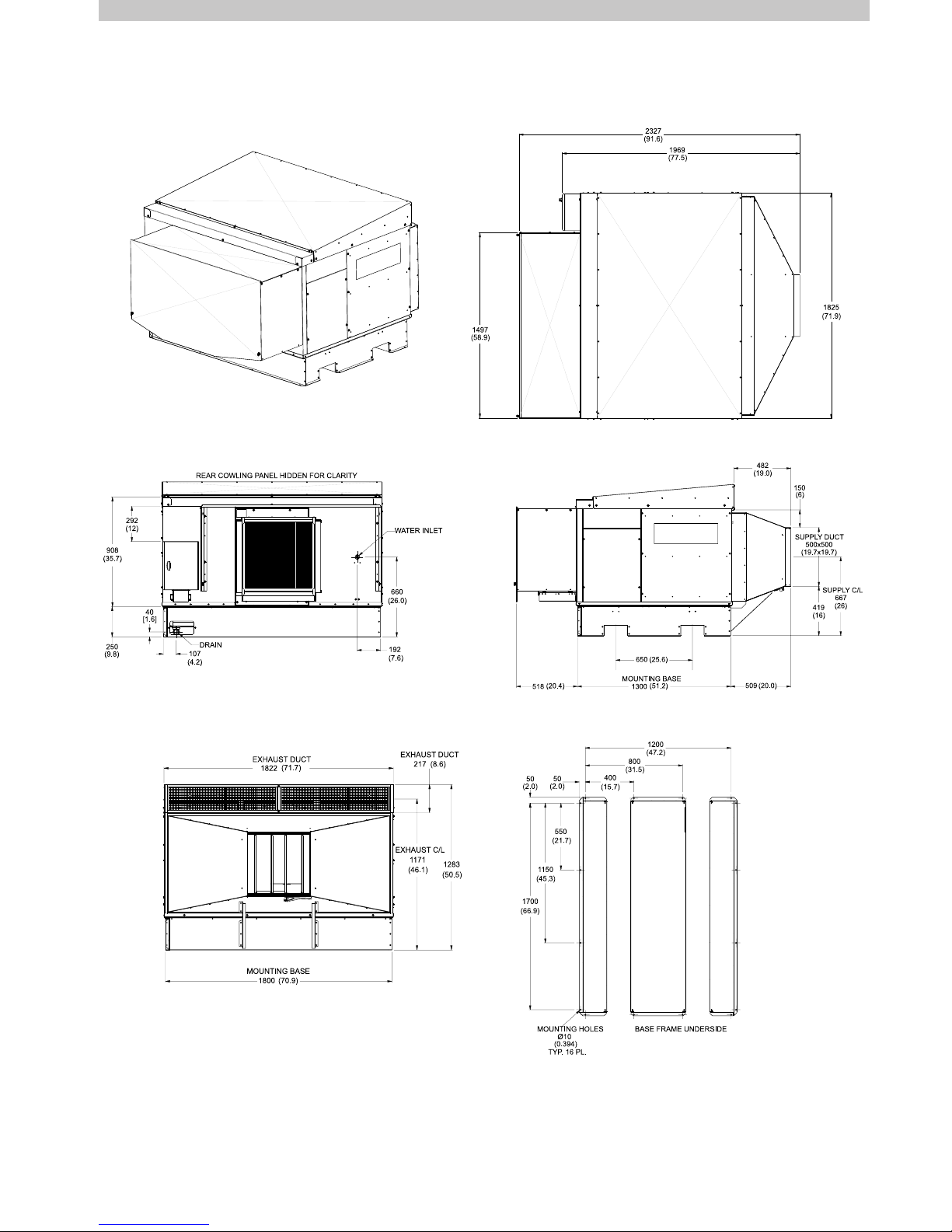
COOLER VIEWS
Dimensions are in mm (inches in brackets).
ISOMETRIC
CW-H15 views shown
TOP
REAR SIDE
BOTTOM
ILL1916-A
ILL1918-A
ILL1917-A
ILL1919-A
ILL1920-A
FRONT
ILL2422-A
6 | CW-H10, H15, H15S, H15S Plus
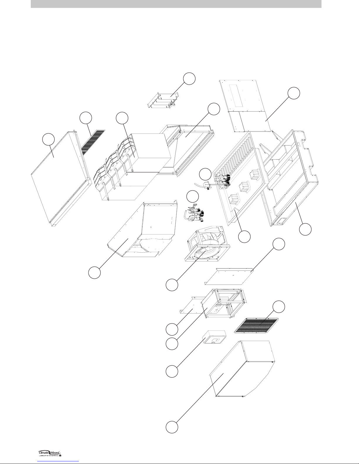
COOLER EXPLODED VIEW
ILL2423-A
1
2
35 6
7
4
5
12
13
14
10
11
15
16
17
8
9
INDEX
DESCRIPTION
1 COWLING ASSEMBLY
2
ELECTRONICS
BOX
3 AIR FILTER ASSEMBLY
4 INLET SAFETY GRILLE ASSEMBLY (Optional, mandatory if Inlet Filter not used)
5 FRONT PANELS
6 MOTOR AND FAN ASSEMBLY
7 INLET TRANSITION ASSEMBLY
8 PUMPS, DRAIN VALV E AND WATER PROBE
9 PUMPS, INLET SOLENOID AND CHLORINATOR
10 TANK ASSEMBLY
11 BASE FRAME ASSEMBLY
12 OUTER PANELS (RHS)
131415
16 EXHAUST GRILLE ASSEMBLY
17
OUTLET TRANSITION ASSEMBLY
DAMPER ASSEMBLY
CORE AND SPREADER ASSEMBLY
EXHAUST LID ASSEMBLY
ILL2423-A
SEELEY INTERNATIONAL
- INSTALLATION MANUAL | 7
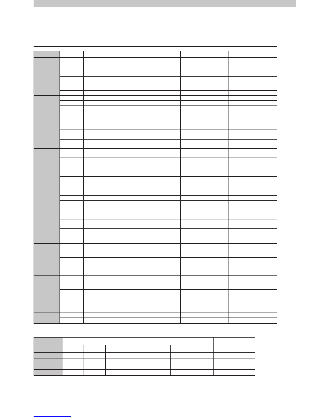
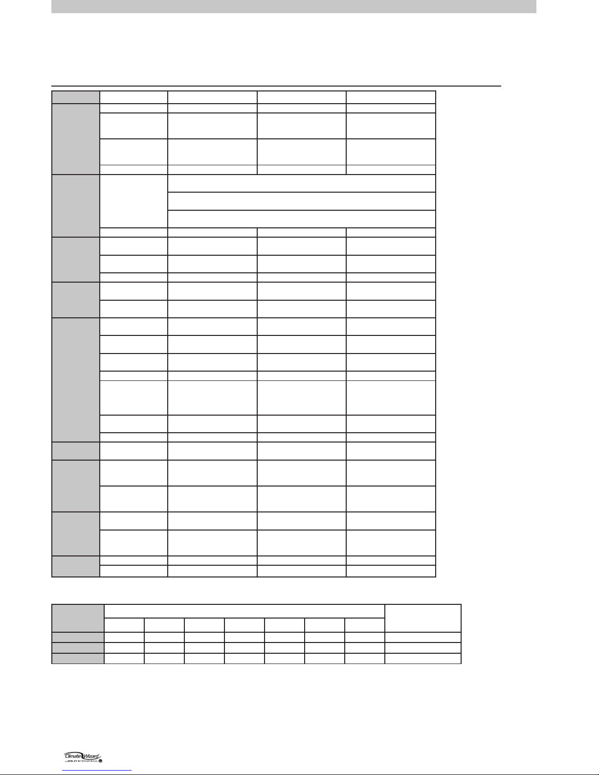
COOLER SPECIFICATIONS
TECHNICAL SPECIFICATIONS - METRIC CW-H MODELS
Specication CW-H10 CW-H15 CW-H15S CW-H15S Plus
Capacity
Airflow
800 L/s @ 140 Pa 1100 L/s @ 150 Pa 1100 L/s @ 130 Pa 1600 L/s @ 80 Pa
Maximum
External Static
Pressure
215 Pa 215 Pa 195 Pa 155 Pa
Nominal
Cooling
Capacity*
18 kW 24 kW 28 kW 40 kW
COP
12 14 16 18
Electrical
Supply
Voltage
380-415V/3N~ 380-415V/3N~ 380-415V/3N~ 380-415V/3N~
Frequency
50 Hz 50 Hz 50 Hz 50 Hz
Rated
Current
3A 3A 3A 3A
Input Power
1.5 kW 1.8 kW 1.8 kW 2.2 kW
Fan/Motor
Type
560mm dia
Backward Curved
560mm dia
Backward Curved
560mm dia
Backward Curved
560mm dia
Backward Curved
Control
Variable Speed
ECM PWM Control
Variable Speed
ECM PWM Control
Variable Speed
ECM PWM Control
Variable Speed
ECM PWM Control
Maximum
Speed
1270 rpm 1350 rpm 1350 rpm 1460 rpm
Heat
Exchanger
Indirect
Evaporative
2 Cores 3 Cores 3 Cores 3 Cores
Direct
Evaporative
None None 3 Chillcel Pads 3 Chillcel Pads
Water
Water Supply
Min. 100kPa, Max
800kPa, 20L/min
Min. 100kPa, Max
800kPa, 20L/min
Min. 100kPa, Max
800kPa, 20L/min
Min. 100kPa, Max
800kPa, 20L/min
Inlet
1/2” male BSP
12V Solenoid
1/2” male BSP
12V Solenoid
1/2” male BSP
12V Solenoid
1/2” male BSP
12V Solenoid
Water
Consumption
44 L/hr 56 L/hr 60 L/hr 72 L/hr
Tank
45 L 65 L 65 L 65 L
Pumps
2 pumps,
13 L/min @ 1.5m head.
230V 50Hz
Input power 30W/ea
3 pumps,
13 L/min @ 1.5m head.
230V 50Hz
Input power 30W/ea
4 pumps,
13 L/min @ 1.5m head.
230V 50Hz
Input power 30W/ea
4 pumps,
13 L/min @ 1.5m head.
230V 50Hz
Input power 30W/ea
Drain
1
1/2
” male BSP
12 V motor
1
1/2
” male BSP
12 V motor
1
1/2
” male BSP
12 V motor
1
1/2
” male BSP
12 V motor
Chlorinators
1 chlorinator 1 chlorinator 1 chlorinator 1 chlorinator
Air Filters
Type G4
washable
305 * 610 * 50mm Qty 2
610 * 610 * 50 Qty 1
305 * 610 * 50mm Qty 3
610 * 610 * 50 Qty 1
305 * 610 * 50mm Qty 3
610 * 610 * 50 Qty 1
305 * 610 * 50mm Qty 3
610 * 610 * 50 Qty 1
Dimensions
Shipping
(Including
Pallet)
2050mm long
1375mm wide
1280mm high
2050mm long
2000mm wide
1280mm high
2050mm long
2000mm wide
1280mm high
2050mm long
2000mm wide
1280mm high
Operating
(Including
Filters and
Cowling)
2330mm long
1230mm wide
1610mm high
2330mm long
1825mm wide
1285mm high
2330mm long
1825mm wide
1285mm high
2330mm long
1825mm wide
1285mm high
Weight
Shipping
(Including
Pallet)
250 kg 320 kg 335 kg 335 kg
Operating
(Including
Filters,
Cowling,
Water)
255 kg 325 kg 340 kg 340 kg
Duct
Connections
Supply
500 x 500 mm 500 x 500 mm 500 x 500 mm 500 x 500 mm
Exhaust
500 x 500 mm 1825 x 220 mm 1825 x 220 mm 1825 x 220 mm
*Tested in accordance with ASHRAE 143 with conditions of 38° C Dry Bulb / 21° C Wet Bulb.
Stand alone cooling capacity may be lower, depending on application.
Frequency
(Hz)
Radiated Sound Power Level (dB(A) re 1pw) Octave Band Centre Frequency Total Sound Power
dB(A) re 1pw
125 250 500 1k 2k 4k 8k
CW-H10
70 60 58 57 54 50 42 63
CW-H15
84 68 65 62 55 51 44 70
CW-H15S
68 69 64 63 60 53 44 73
CW-H15S Plus 71 70 66 64 61 55 48 75
8 | CW-H10, H15, H15S, H15S Plus
COOLER SPECIFICATIONS
TECHNICAL SPECIFICATIONS - IMPERIAL CW-H MODELS
Specication CW-H15 CW-H15S CW-H15S Plus
Capacity
Airflow
2330 CFM @ 0.60 in WG 2330 CFM @ 0.52 in WG 3390 CFM @ 0.32 in WG
Maximum
External Static
Pressure
0.86 in WG 0.78 in WG 0.62 in WG
Nominal
Cooling
Capacity*
82,000 BTU/hr 93,800 BTU/hr 135,500 BTU/hr
EER
46 53 61
Electrical
Supply
Voltage / Frequency /
Current
Option 1 - 380-480V/3~/60Hz
3A per Phase / 8.5 MCA / 15 MOPD
Option 2 - 200-240V/3~/60Hz
6A per Phase / 14.5 MCA / 20 MOPD
Option 3 - 200-277V/1~/60Hz
8A per Phase / 11.5 MCA / 15 MOPD
Input Power
1.8 kW 1.8 kW 2.2 kW
Fan/Motor
Type
22” dia
Backward Curved
22” dia
Backward Curved
22” dia
Backward Curved
Control
Variable Speed
ECM PWM Control
Variable Speed
ECM PWM Control
Variable Speed
ECM PWM Control
Maximum Speed 1350 rpm 1350 rpm 1460 rpm
Heat
Exchanger
Indirect
Evaporative
3 Cores 3 Cores 3 Cores
Direct
Evaporative
None 3 Chillcel Pads 3 Chillcel Pads
Water
Water Supply
Min. 15 psi, Max 115 psi,
5.3 gal/min
Min. 15 psi, Max 115 psi,
5.3 gal/min
Min. 15 psi, Max 115 psi,
5.3 gal/min
Water
Consumption
15 gal/hr 16 gal/hr 19 gal/hr
Inlet
1/2” male NPT
12V Solenoid
1/2” male NPT
12V Solenoid
1/2” male NPT
12V Solenoid
Tank 17 gal 17 gal 17 gal
Pumps
3 pumps,
3.4gal/min @ 4.9’ head.
220V 60Hz
Input power 32W/ea
4 pumps,
3.4gal/min @ 4.9’ head.
220V 60Hz
Input power 32W/ea
4 pumps,
3.4gal/min @ 4.9’ head.
220V 60Hz
Input power 32W/ea
Drain
1
1/2
” male BSP
12 V motor
1
1/2
” male BSP
12 V motor
1
1/2
” male BSP
12 V motor
Chlorinators 1 chlorinator 1 chlorinator 1 chlorinator
Air Filters
MERV 8 washable 12 * 24 * 2” Qty 3
24 * 24 * 2” Qty 1
12 * 24 * 2” Qty 3
24 * 24 * 2” Qty 1
12 * 24 * 2” Qty 3
24 * 24 * 2” Qty 1
Dimensions
Shipping
including pallet
81” long
79” wide
51” high
81” long
79” wide
51” high
81” long
79” wide
51” high
Operating including
filters,
cowling
92” long
72” wide
51” high
92” long
72” wide
51” high
92” long
72” wide
51” high
Weight
Shipping
including pallet
705 lb 740 lb 740 lb
Operating including
filters,
cowling, water
715 lb 750 lb 750 lb
Duct
Connections
Supply 20 x 20” 20 x 20” 20 x 20”
Exhaust 70 x 8.5” 70 x 8.5” 70 x 8.5”
*Tested in accordance with ASHRAE 143 with conditions of 100° F Dry Bulb / 70° F Wet Bulb.
Stand alone cooling capacity may be lower, depending on application.
Frequency
(Hz)
Radiated Sound Power Level (dB(A) re 1pw) Octave Band Centre Frequency Total Sound Power
dB(A) re 1pw
125 250 500 1k 2k 4k 8k
CW-H15
84 68 65 62 55 51 44 70
CW-H15S
68 69 64 63 60 53 44 73
CW-H15S Plus
71 70 66 64 61 55 48 75
SEELEY INTERNATIONAL
- INSTALLATION MANUAL | 9
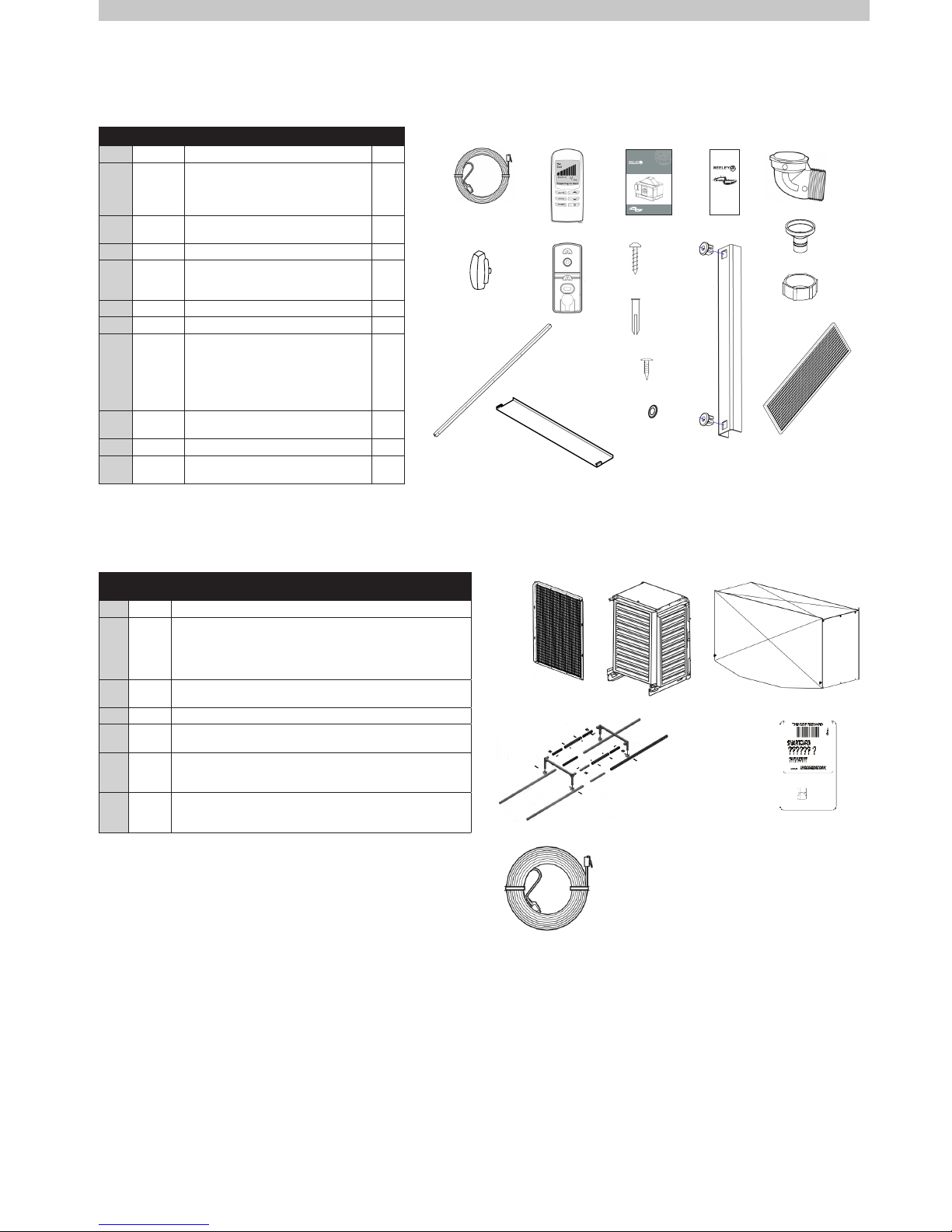
COOLER CONTENTS
COOLER INSTALLATION COMPONENTS
OPTIONAL COMPONENTS
Item Part No. Description QTY
1 834245 Control Cable 20m (65’) 1
2A
2B
2C
2D
114279
584331
804644
805306
Wall Control CW-H
Plate Mount Wall Control
Screw Pan Ph 6AB*1" ZNP
Plug Rawl Yellow 5mm Dia
1
1
2
2
3 859379
Instruction - Installation, Operation,
Maintenance
1
4 879345 Warranty Card (USA Only) 1
5A
5B
5C
861883
593104
861593
Adaptor Drain Elbow
Adaptor, Drain 32/20mm
Nut, Pipe Fitting 1.5” BSP
1
1
1
6 - Handle, Control Box 1
7 637994 Exhaust Centre Post 1
8A
8B
8C
8D
8E
8F
805597
804446
804422
864341
864385
864372
Screw 8AB x ½” Pan Phill SS
Screw SEMS HX 14*3/4" ZNP
Plastic Grommet Size 14
Screw Set SHCS M6*35mm SS
Washer Flat M6*12.5OD*1.2 SS
Washer Flat NYLON M8*16OD
10
11
5
4
4
4
9 931685 Exhaust Side Rails (1176mm Long)
(UNDER LID)
2
10 834785 Exhaust Grille (869x205) (UNDER LID) 2
11 637999
Exhaust Cap (UNDER LID)
CW-H15S Plus Only
2
Item
Seeley
Part
Description
1 120202 Inlet Air Safety Grille
2A
2B
2C
2D
120409
120379
120430
120447
Inlet Air Filter Frame inc. Filters (CW-H10)
Inlet Air Filter Frame inc. Filters (CW-H15, H15S, H15S Plus)
Bushre Rated Inlet Air Filter Frame inc. Filters (CW-H10)
Bushre Rated Inlet Air Filter Frame inc. Filters
(CW-H15, H15S, H15S Plus)
3A
3B
120416
120386
Inlet Air Filter Cowling (CW-H10)
Inlet Air Filter Cowling (CW-H15, H15S, H15S Plus)
4 094724 Control Cable 40M
5A
5B
134192
134215
Roofstand 0-10O (CW-H10)
Roofstand 0-10O (CW-H15, H15S, H15S Plus)
6A
6B
6C
094397
093970
TBC
CW-H15S Conversion 380-480V/3~
CW-H15S Conversion 220-240V/3~
CW-H15S Conversion 220-240V/1~
7A
7B
7C
094366
TBC
TBC
High Altitude Smartcard 380-480V/3~ (CW-H15)
High Altitude Smartcard 200-240V/3~ (CW-H15)
High Altitude Smartcard 200-240V/1~ (CW-H15)
ITEM 1. ITEM 2A
ITEM 2B
ITEM 9
ITEM 10
ITEM 11
ITEM 2C
ITEM 2D
ITEM 3
ITEM 4
ITEM 5A
ITEM 6
ITEM 5C
ITEM 5B
INSTALLATION,OPERATION&MAINTENANCE
(English)(CW-H15)
ClimateWizard–CW-H10,CW-H15
IndirectEvaporativeCooler
WARRANTYINFORMATION
DUCTEDINDIRECTEVAPORATIVE
AIRCOOLER
INTERNATIONAL
ITEMS 7&8C
ITEMS 8A, 8B&8D
ITEMS 8E&8F
ITEM 1 ITEMS 2A &2B
ITEM 4
ITEM 16
ITEM3
ITEM 5 ITEM 7ITEM 6
Not Shown
ILL2425-A
ILL2424-A
ITEM 4
10 | CW-H10, H15, H15S, H15S Plus
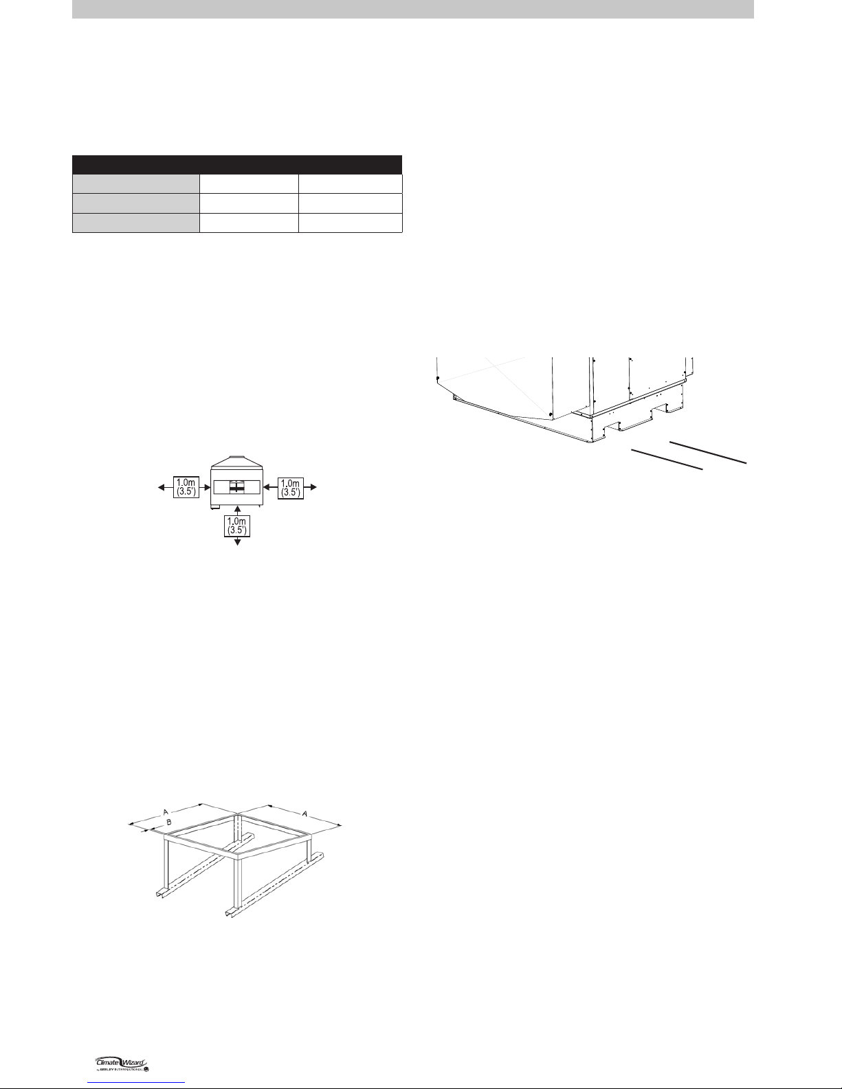
INSTALLATION
COOLER LOCATION
Check the proposed cooler location, to ensure that it is
structurally capable of supporting the weight of the cooler, or
provide an adequate alternate load bearing structure.
Model Shipping Weight Operating Weight
CW-H10 250kg (550 lb) 255kg (560 lb)
CW-H15 320kg (705 lb) 325kg (715 lb)
CW-H15S, H15S Plus 335kg (740 lb) 340kg (750 lb)
Always locate the cooler where it will receive a plentiful supply
of fresh air, NOT in a recess where it may be starved for air or
where the air is polluted.
Air exiting the exhaust hood is warm and heavily laden with
moisture. Ensure the cooler’s exhaust outlet location will not
cause corrosion or damage to other nearby items. Do not allow
exhaust air to re-circulate into the air intake of the cooler.
Ensure the location is a minimum of:
• 3.0m (10’) from a solid fuel heater ue,
• 1.5m (5’) from a gas ue,
• 5.0m (16’) from a sewer vent
• Rear = Min 1.0m (3.5’) from a wall, 1.0m (3.5’) at sides to
allow easy access for maintenance and core replacement.
ILL1925-A
Allow adequate access to and around the cooler for
maintenance. Provision must be made for access to electricity,
water supplies and drains.
Note! Do you need to discuss the installation of items like
safety anchor points with the customer?
MOUNTING/SUPPORT
Industry standard support frames can be used with this cooler.
Recommended steel specication:
50 x 50 x 3mm (2” x 2” x 1/8”) RHS Galvanized or Painted
Specic CW-H Roofstands are available for order via Seeley
International to suit cooler size and accommodating 5 or 10
degree roof pitches.
CW-H10: 0-10º - P/No. 134192
CW-H15: 0-10º - P/No. 134215
ILL2426-A
CW-H10:
A = 1300mm (51.2”) x 1206mm (47.5”)
CW-H15, H15S, H15S Plus:
A = 1300mm (51.2”) x 1800mm (70.9”)
CW-H10, CW-H15, H15S, H15S Plus:
B = 50mm min (2” min.)
Angle to match roof pitch
UNPACKING THE COOLER
The cooler will be delivered wrapped in a plastic stretch wrap
lm which will need to be removed before installation. A small
bag of installation components along with the exhaust transition
side rails and grilles can be found under the lid of the main
cabinet of the cooler. The exhaust transition will need to be
raised into place before operation.
The wall control and communications cable, along with ancillary
mount plates, fasteners and drain adaptors will need to be
placed aside for later connection.
WARNING: Once unwrapped, the exhaust transition assembly
should be tted together as soon as practicable to avoid loose
components becoming lost/damaged and/or a hazard.
MOVING THE COOLER
The cooler has in-built fork-truck tyne openings in the base for
ease of movement. The openings can also be used with lifting
straps or slings (refer diagram & see below).
ILL1916-A
Min. Fork tyne gap =
460mm (18.2”)
LIFTING THE COOLER
The cooler may be lifted either by fork-truck or crane with slings.
The method for lifting by crane is by lifting straps through the
cooler base fork-truck tyne openings. Do not attempt to lift using
any cabinet features or by retro-tting lifting lugs. The cabinet
may be damaged and/or lift safety compromised.
It is recommended to use a spreader bar on the straps or slings
and/or to protect the upper edges of the cooler with a corner
protector beneath the lifting straps to avoid any damage to the
cabinet during the lift.
VIBRATION ISOLATION
Wae pads are recommended to be used under each corner
of the cooler. Pad size approx. 200mm (8”) x 200mm (8”). Use
industry standard methods of xing to the building structure.
DRIP-TRAY
When Climate Wizard coolers are installed indoors, or
anywhere that water leakage could cause damage, install
a corrosion resistant drip tray under the whole machine.
Recommended sizes:
CW-H10:
1500w x 1300d x 50h mm (59”w x 51”d x 2”h)
CW-H15, H15S, H15S PLUS:
1500w x 1900d x 50h mm (59”w x 75”d x 2”h)
Apply silicone sealant between drip-tray and cooler base at
every xing.
SUPPLY AIR DUCT CONNECTIONS
Vibration absorbing exible connections are recommended
for all duct connections to the cooler, for any ducts that are
attached to the building structure. All ducts attached to the
exible connection must be independently supported.
SEELEY INTERNATIONAL
- INSTALLATION MANUAL | 11
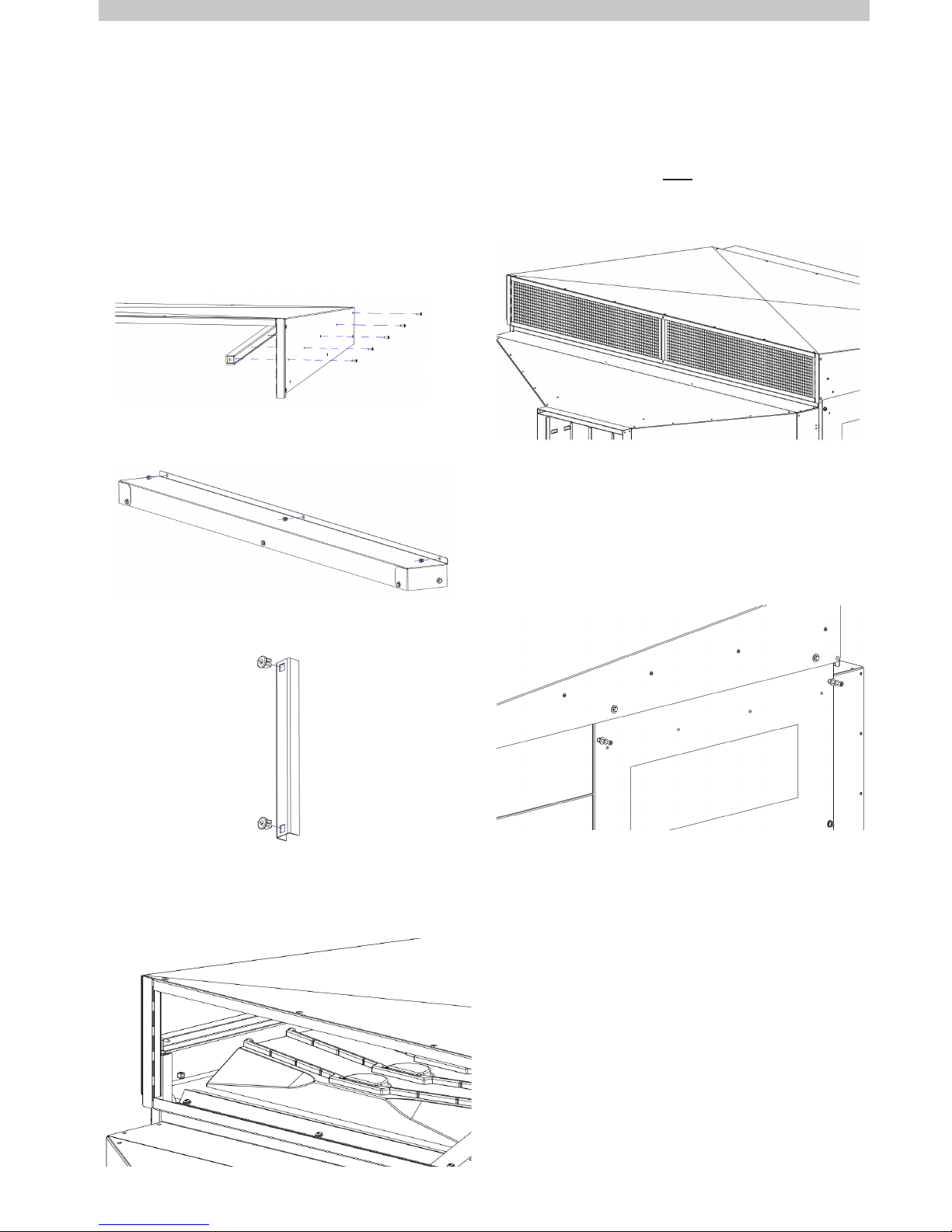
INSTALLATION cont.
8. Fit the supplied 4 x M6 x 35MM SET SCREW, STAINLESS
STEEL FLAT WASHER, NYLON FLAT WASHER to the tops
of both core access doors. Apply a liberal coat of anti-seize
paste to the screw thread prior to tment.
EXHAUST TRANSITION ASSEMBLY
The exhaust transition is supplied in knock-down form and its
components are to be found beneath the lid of the cooler and
inside the component kit.
1. Lift the large top panel and locate;
• 2 x EXHAUST SIDE RAILS (1176mm Long)
• 2 x EXHAUST GRILLE (869 X 205)
• 2 x EXHAUST CAPS (CW-H15S Plus Only)
2. Fit the EXHAUST SIDE RAILS to the inside vertical faces
of the large top panel with the supplied 10 x SCREW PAN
PHILLIPS 8AB*1/2” SS. Ensure the foam seal faces down.
ILL2427-A
3. Fit the supplied 3 x PLASTIC GROMMET SIZE 14 to the
rear lid panel upstand square holes.
ILL2428-A
4. Fit the supplied 2 x PLASTIC GROMMET SIZE 14 to the
EXHAUST CENTRE POST.
ILL2429-A
5. Position the large top panel over the top of the cooler, with
the rear u-channel over the top of the upstand, the side rails
sitting on the tops of the cooler side walls and the end posts
sitting on the outside of the front tray.
ILL2428-A
6. Slip the 2 x EXHAUST GRILLE and 1 x EXHAUST CENTRE
POST into position, retained inside the top panel front
u-channel.
CW-H15S Plus ONLY: Before tting to the cooler, slide an
EXHAUST CAP over the back of each EXHAUST GRILLE.
The EXHAUST CAP covers the top portion of the EXHAUST
GRILLE, and is designed to optimise the CW-H15S
Supercool performance.
ILL2431-A
7. Screw the exhaust transition assembly to the cooler body
with the supplied 11 x SCREW SEMS HEX 14 x 3/4” ZP.
3 x Rear Upstand, 3 x Left Side, 3 x Right Side, 2 x Centre
Post.
ILL2432-A
EXHAUST DUCT CONNECTION REQUIREMENTS
If required, the exhaust discharge opening may be ducted away
from the cooler. When designing the exhaust duct please note
the following;
• The exhaust air is warm and heavily laden with moisture.
Ensure the exhaust opening is located and oriented in such a
way as to avoid exhaust air re-entering the cooler inlet.
• Access to the heat exchanger cores requires the removal of
the cooler lid/exhaust transition. Ensure any additional ducting
is readily removable and/or lightweight.
• Where an installation requires extended exhaust ducts, the
increase in static load should not exceed 20 Pa (0.08 in wg).
12 | CW-H10, H15, H15S, H15S Plus
INSTALLATION cont.
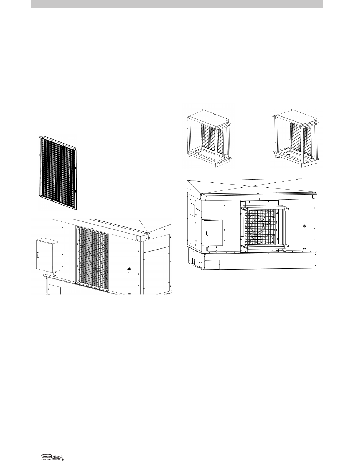
INLET AIR FILTER ASSEMBLY OR SAFETY GRILLE
Climate Wizard coolers SHOULD NEVER BE INSTALLED
WITHOUT DUST FILTERS.
Use either the Inlet Air Filter Assembly supplied from the factory
or use the cooler with pre-ltered air to EN779 G4 or ASHRAE
52.2 MERV8 standards.
Should the Inlet Air Filter Assembly not be required an Inlet Air
Safety Grille is available and MUST be tted for safety reasons.
Other Safety Grilles cannot be substituted.
The Inlet Air Filter Assembly or Safety Grille is supplied in
separate cartons when shipped with the Climate Wizard.
OPTION 1 – INLET AIR SAFETY GRILLE (FOR USE WITH
PRE-FILTERED AIR ONLY)
CW-H10, CW-H15, H15S, H15S Plus: = P/N 120102
OPTION 2 - INLET AIR FILTER ASSEMBLY
CW-H10: = P/N 120409
CW-H15, H15S, H15S Plus: = P/N 120379
1. Remove the air lters from their shipping position in the
frame.
2. Fit the Inlet Air Filter Assembly using the 4 x M6 x 16mm Set
Screws and Washers pre-tted to the front face of the air
inlet recess. Ensure the frame is centred around the fan inlet
cone.
ILL2433-A
Fit the Inlet Air Safety Grille
using the 4 x M6 X 16MM SET
SCREWS AND WASHERS pre-
tted to the inside surfaces of
the air inlet recess.
ILL2434-A
3. Re-t the air lters, ensuring the sticker showing direction of
air ow is the correct way round.
ILL2436-A
ILL2437-A
CW-H10 CW-H15, H15S, H15S Plus
ILL2435-A
SEELEY INTERNATIONAL
- INSTALLATION MANUAL | 13
INSTALLATION cont.
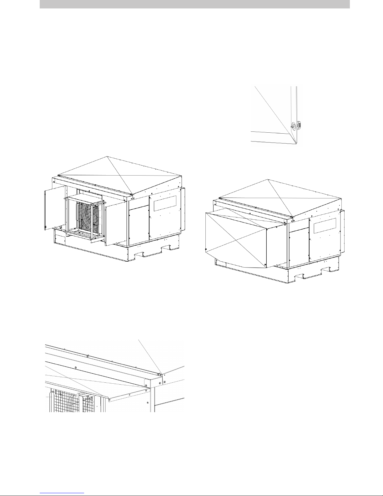
INLET AIR FILTER COWLING ASSEMBLY
Climate Wizard coolers installed outside should be tted with an
inlet air cowling assembly to protect the air lters from exposure
to water. It features a detachable front panel for easy access to
the lters.
The Inlet Air Cowling Assembly is supplied in a separate carton
when shipped with the Climate Wizard. It contains a small bag
of fasteners required for tment to the cooler.
CW-H10: = P/N 120416
CW-H15, H15S, H15S Plus: = P/N 120386
1. Fit the 2 x Cowling Side Panels. Ensure the black plastic
tting is at the bottom of the panel.
a. CW-H15, H15S, H15S Plus: – Screw the cowling side
panels to the cooler using the supplied 6 x SCREW SEMS
HEX 14 x 3/4” ZP into the pre-tted plastic grommets tted
to the cooler body.
4. Screw the cowling side panel and the top panel to the cooler
body with supplied 6 x SCREW SEMS HEX 14 x 3/4” ZP.
5. Fit the supplied 2 x quarter-turn, self-ejecting fasteners to
the Cowling Front Panel. Ensure the supplied split washer is
tted as shown.
b. CW-H10 – Fit the right hand side panel as above.
Fit the left hand side panel using the same pre-tted M6 x
16mm Set Screws and Washers used to t the lter frame to
the cooler.
2. Fit the supplied 6 x PLASTIC GROMMET SIZE 14 to the
sides of the Cowling Top Panel
3. Remove the pre-tted centre and right hand screws from
the cooler lid back panel. Slip the long large upstand of the
Cowling Top Panel under the lip of the cooler lid back panel
and re-t the screws.
ILL2438-A
ILL2439-A
6. Rest the return fold of the cowling front panel on the lip of
the top panel. Secure the bottom corners using the quarterturn self-ejecting fasteners.
ILL2440-A
ILL2441-A
14 | CW-H10, H15, H15S, H15S Plus
INSTALLATION cont.
WATER SUPPLY INSTALLATION
Climate Wizard requires a permanent water supply to be
connected.
Installation of the water supply to the cooler must conform to
local plumbing rules, regulations and standards:
The following specications for water supply are required:
• Water Connections:
½” BSP (Aus/Eur), ½” NPT (USA)
male connection supplied suitable for a compression tting.
• Water Supply:
100kPa (15psi) - 800 kPa (115psi)
MAXIMUM @ 20L/min (5.3 gal/min)
• Water Supply Temperature:
40°C (105°F) MAXIMUM
• Water Supply Salinity:
100 to 1150µS/cm
Important! If the water pressure exceeds this maximum
specication then a pressure reducing valve is required and
must be supplied and tted by the installer.
The installer must provide a manual 1/4 turn ball type shut o
valve (do not use a stop cock) in the water supply line adjacent
to the cooler, subject to local plumbing regulations. This allows
the water supply to be isolated whenever work needs to be
done on the cooler.
In areas subject to freezing, the water line needs a drain
down facility.
WATER SUPPLY FILTRATION
Seeley International requires an inlet lter to be installed on
the water supply line, external to the Climate Wizard cooler
to prevent any debris from entering and damaging cooler
components.
Important! Flush the water pipe to remove any contaminants
(swarf, lings or dirt) before nal tting. Contaminants can lodge
in the solenoid, preventing it from functioning correctly.
Climate Wizard’s water management system is designed to
use water that is suitable to be classied as ‘potable’ and t for
human consumption. If alternative water (including rain water)
is to be used that contains high levels of salinity, hardness,
acidity or chemical contaminants, then additional ltration or
treatment systems should be employed to render the water
‘potable’.
WATER HAMMER
Not all installation pipeworks are the same, and some may
require additional prevention against water hammer.
If water hammer is a problem, it is the responsibility of the
Installer to t an appropriate water hammer arresting device
external to the cooler.
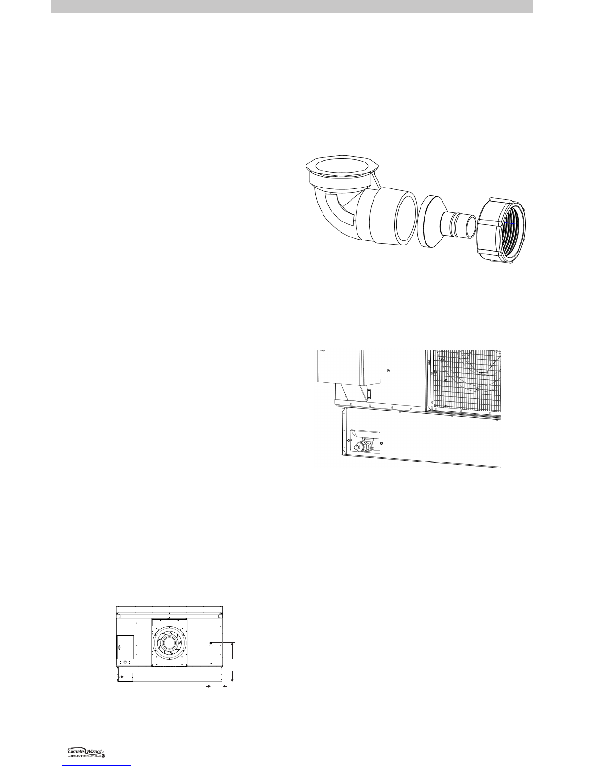
WATER DRAIN INSTALLATION
Climate Wizard coolers require a permanent water drain to
be connected. A built-in Drain Valve, controlled by the water
management system, releases water from the cooler when
required.
The cooler installation kit contains components to congure the
Drain Valve discharge to one of the following options;
ACCESS COVER
FOR DRAINVALVE
CONNECTION
WATER CONNECTION
1/2”MALE NIPPLE
(Water connection may
require an adaptor to
suit local pipe sizes)
660mm
(26”)
200mm
(7.9”)
DO NOT OVER-TIGHTEN
OR CROSS-THREAD
COMPRESSION
FITTINGS
ONTO THE PLASTIC
WATER INLET NIPPLE.
REAR VIEW
ILL1940-B
The correct drain system must be used. Water drained from
the drain valve is high in salinity and must be carried away
to a suitable discharge point on the building or property, in
accordance with local regulations. It is a requirement of
Seeley International - Never drain the water directly onto
the roof.
• Down Discharge 1.5” (40mm) BSP Male
• Down Discharge 20mm Push On Hose
• Rear Discharge 1.5” (40mm) BSP Male
• Rear Discharge 20mm Push On Hose
An access panel can be removed for rear discharge options.
ILL2442-A
ILL2442-A
 Loading...