

Seeley Breezair EXH Series Installation And Operating Instructions Manual

INDEX
SAF ETY ......................................................................................................... 1
OPERATING INSTRUCTIONS
Thermostat Range ......................................................................................... 2
Using the SENSORTOUCH ® Remote Control ................................................... 3
Using the SENSORTOUCH ® Wall Control ......................................................... 7
Maintenance .................................................................................................. 9
Pre-Assembly Inspection ............................................................................... 10
iNSTALLATiON iNSTRUCTiONS
Installation Details .......................................................................................... 11
Water Installation ........................................................................................... 12
Electrical Installation ...................................................................................... 13
SENSORTOUCH ® Wall Control ........................................................................ 13
SENSORTOUCH ® Remote Control ................................................................... 14
Testing the cooler ........................................................................................... 16
Installation Checklist ...................................................................................... 17
TROUBLE SHOOTING ................................................................................. 18
APPENDIXA- Wiring Diagrams ..................................................................... 20
SAFETY INSTRUCTIONS
important Safety instructions and
Warnings
WARNING: The warnings and safety
instructions in this manual must be
followed to reduce the risk of fire,
electric shock or injury, and to provide
reasonable safety and efficiency in
using this Evaporative Air Cooler. The
operator is responsible for following
the warnings and instructions in this
manual and on the cooler.
Read this entire manual before
proceeding to install the cooler.
Restrict the use of this cooler to
persons who read, understand and
can follow the warnings and
instructions in this manual and on
the cooler. NEVER ALLOW
CHILDREN TO OPERATE THE
COOLER.
Failure to observe these warnings
and instructions will void
manufacturer's warranties and will
discharge the manufacturer of all
liability.
CAUTION!
ALWAYS disconnect the cooler
from the power supply before
commencing maintenance
procedures.
During maintenance procedures,
NEVER use a naked flame for any
inspection or cleaning purpose as a
fire could be caused by a flame
coming into contact with the cooler
materials.
Avoid Dangerous Situations:
Protect the cooler from all sources
of ignition because polymers and
cooling pads will burn.
NEVER use a water hose to squirt
the interior of the cooler for cleaning
as residual water could damage
electrical components and create the
risk of fire and/or electric shock to
the user after re-assembly.
INSTALLATION, REPAIR AND
OPERATION
• All installation and repair work
must conform to local electrical, water
supply and environmental codes,
rules and regulations and applicable
national standards.
• All installation, maintenance and
repair work must be done by a
licensed and qualified electrician
and/or a qualified, experienced
heating, ventilating, air
conditioning technician. All such
work must be effected with factory
authorized spare parts only.
• Disconnect electrical power at the
fuse or circuit breaker box before
installation commences. ALWAYS
turn OFF the isolating switch
(disconnect) located on the electronic
module inside the cooler BEFORE
commencing any maintenance
• Use only the power supply voltage
shown on the motor/cabinet
nameplate.
• Do not install or service the air
cooler during rain, high wind or severe
weather conditions.
• Keep children, bystanders and
animals at a safe distance, a minimum
of 30ft (10m) away from working
areas.
• Dress safely. Wear non-skid shoes
when working at high levels and roofs.
Do not wear loose clothing or personal
accessories while installing or
servicing the air cooler as they may
become caught in moving parts.
• Keep loose hair, loose clothing,
fingers and all other parts of the body
away from openings and moving
parts.
• Check the cooler for worn, loose,
missing, or damaged parts before
operation.
• If you work with power tools, wear
protective eyewear and gloves.
• Take care when lifting or raising the
air cooler to its final location. Use safe
equipment and never attempt to lift the
cooler alone. Always have assistance.
Otherwise you might damage the
cooler or the building or injure
yourself.
• Ground Fault Circuit Interrupter
(GFCI) protection should be provided
on the circuit supplying this air cooler.
Receptacles are available with built-in
GFCI protection.
• Air coolers installed on roofs must
not have the waste water directed
onto the roof as stains will occur.
Connect the cooler drain outlet to a
gutter or drain pipe using a suitable
hose.
• Always use the correct tools.
• WARNING! the packaging plastic
on this cooler can be a safety hazard.
Dispose of carefully.
• Never drill holes in the pan or walls
of the cooler.
• Avoid dangerous situations. Do not
use the cooler in the presence of
flammable liquids or gasses to avoid
creating fire or explosion. This air
cooler is NOT flame retardant. Afire
may result from contact with a flame
or from an electrical short.
• Use of wrong replacement parts
creates risk of severe electric shock
and fire which may result in serious
property damage, personal injury or
death.
WATER PUMP
The water pump is supplied with this
cooler and is factory fitted into its
correct location.
Ensure that it is properly secured and
upright as intended.
There is no need to adjust the water
flow since the cooler is designed to
operate with maximum cooling at low
air velocities.
Water pump replacement
Factory authorized pumps are fitted
with thermal overload protection.
Water pumps may seize up and
overheat, creating a fire risk. Pumps
that have thermal overload protection
are designed to shut off the pump if the
motor overheats.
Factory Authorized water pump
Seeley "Tornado" pump (part no.
095905)
"Power Clean" Style Timed Pumps
Under no circumstances are "Power
Clean" style timed pumps to be
used in any Breezair evaporative air
cooler. Use of these devices or any
other non-approved device will cause
serious damage to the special safety
circuits of this cooler. Failure to follow
this instruction will VOID ALL
WARRANTY and may create severe
risk of electric shock and fire!
FAN MOTOR
This cooler is supplied with a fan motor
made by the cooler manufacturer.
USE ONLYTHE AUTHORIZED FAN
MOTOR SUPPLIED.
Failure to follow this instruction will
VOID ALL WARRANTY and may
create severe risk of electric shock
and fire!
Factory Authorized Fan Motor
Seeley Direct Drive motors:
750W (1HP) motor part# 095943
1500W (2HP) motor part # 095967
The fan motor is equipped with inbuilt
overheating protection that will reset
automatically on cool=down to a safe
temperature. This may take up to 45
minutes.
CIRCUIT BREAKER
PROTECTION
This cooler is fitted with circuit breaker
protection for the fan motor and pump.
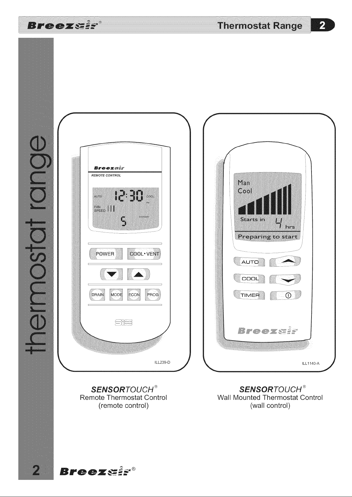
SENSORTOUCH ®
Remote Thermostat Control
(remote control)
SENSORTOUCH ®
Wall Mounted Thermostat Control
(wall control)
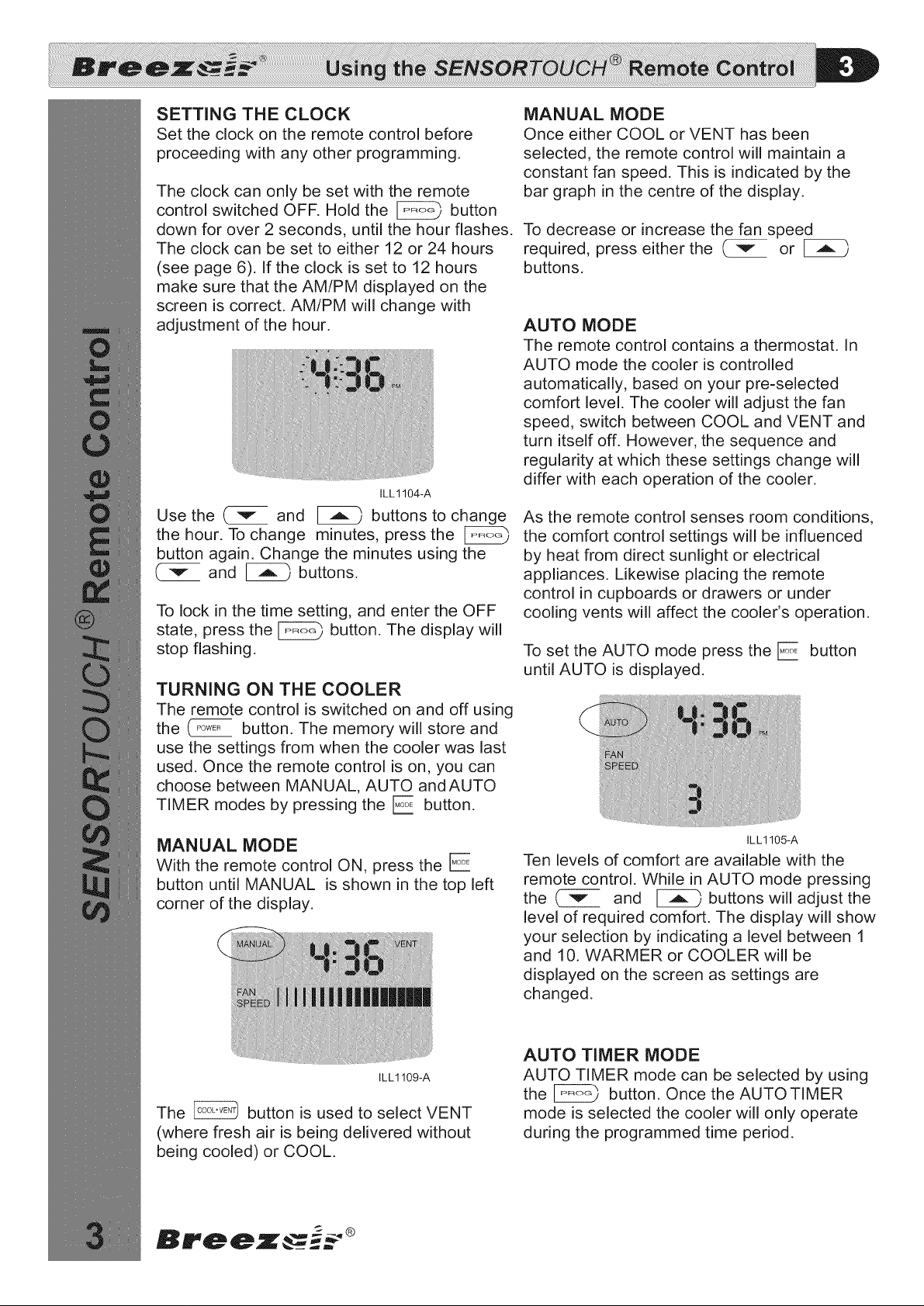
SETTING THE CLOCK
Set the clock on the remote control before
proceeding with any other programming.
The clock can only be set with the remote
control switched OFF. Hold the _ button
down for over 2 seconds, until the hour flashes.
The clock can be set to either 12 or 24 hours
(see page 6). If the clock is set to 12 hours
make sure that the AM/PM displayed on the
screen is correct. AM/PM will change with
adjustment of the hour.
ILL1104-A
Use the ( _" and _ buttons to change
the hour. To change minutes, press the
button again. Change the minutes using the
( v- and _ buttons.
To lock in the time setting, and enter the OFF
state, press the _ button. The display will
stop flashing.
TURNING ON THE COOLER
The remote control is switched on and off using
the CPoWE_button. The memory will store and
use the settings from when the cooler was last
used. Once the remote control is on, you can
choose between MANUAL, AUTO andAUTO
TIMER modes by pressing the E button.
MANUAL MODE
Once either COOL or VENT has been
selected, the remote control will maintain a
constant fan speed. This is indicated by the
bar graph in the centre of the display.
To decrease or increase the fan speed
required, press either the (_," or
buttons.
AUTO MODE
The remote control contains a thermostat. In
AUTO mode the cooler is controlled
automatically, based on your pre-selected
comfort level. The cooler will adjust the fan
speed, switch between COOL and VENT and
turn itself off. However, the sequence and
regularity at which these settings change will
differ with each operation of the cooler.
As the remote control senses room conditions,
the comfort control settings will be influenced
by heat from direct sunlight or electrical
appliances. Likewise placing the remote
control in cupboards or drawers or under
cooling vents will affect the cooler's operation.
To set the AUTO mode press the E button
until AUTO is displayed.
MANUAL MODE
With the remote control ON, press the E
button until MANUAL is shown in the top left
corner of the display.
ILL1109-A
The _ button is used to select VENT
(where fresh air is being delivered without
being cooled) or COOL.
ILL1105-A
Ten levels of comfort are available with the
remote control. While in AUTO mode pressing
the ( v- and _ buttons will adjust the
level of required comfort. The display will show
your selection by indicating a level between 1
and 10. WARMER or COOLER will be
displayed on the screen as settings are
changed.
AUTO TIMER MODE
AUTO TIMER mode can be selected by using
the _ button. Once the AUTO TIMER
mode is selected the cooler will only operate
during the programmed time period.
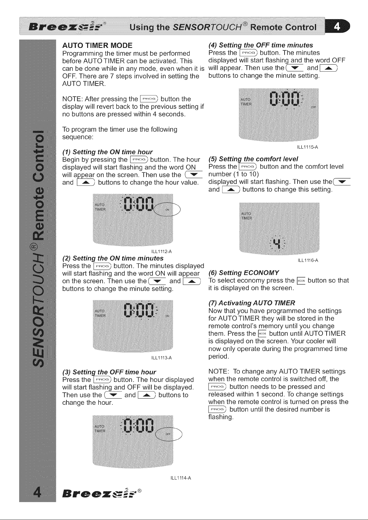
AUTO TIMER MODE (4) Setting the OFF time minutes
Programming the timer must be performed Press the _ button, The minutes
before AUTO TIMER can be activated. This displayed will start flashing and the word OFF
can be done while in any mode, even when it is will appear, Then use the{ _" and
OFF. There are 7 steps involved in setting the buttons to change the minute setting.
AUTO TIMER.
NOTE: After pressing the _ button the
display will revert back to the previous setting if
no buttons are pressed within 4 seconds.
To program the timer use the following
sequence:
ILL1115-A
(1) Setting the ON time hour
Begin by pressing the _ button, The hour
displayed will start flashing and the word ON
will a_ on the screen. Then use the ( v
and _ buttons to change the hour value.
(5) Setting the comfort level
Press the _ button and the comfort level
number (1 to 10)
displayed will start flashing, Then use the( -v
and _ buttons to change this setting.
ILL1112-A
(2) Setting the ON time minutes
Press the _ button. The minutes displayed
will start flashing and the word ON will appear
on the screen. Then use the( "_" and
buttons to change the minute setting.
ILL1113-A
(3) Setting the OFF time hour
Press the _ button. The hour displayed
will start flashing and OFF will be displayed.
Then use the ( _ and _ buttons to
change the hour.
ILL1116-A
(6) Setting ECONOMY
To select economy press the E button so that
it is displayed on the screen.
(7) Activating AUTO TIMER
Now that you have programmed the settings
for AUTO TIMER they will be stored in the
remote contrors memory until you change
them, Press the E button until AUTO TIMER
is displayed on the screen, Your cooler will
now only operate during the programmed time
period.
NOTE: To change any AUTO TIMER settings
when the remote control is switched off, the
button needs to be pressed and
released within 1 second. To change settings
when the remote control is turned on press the
button until the desired number is
flashing.
ILL1114-A
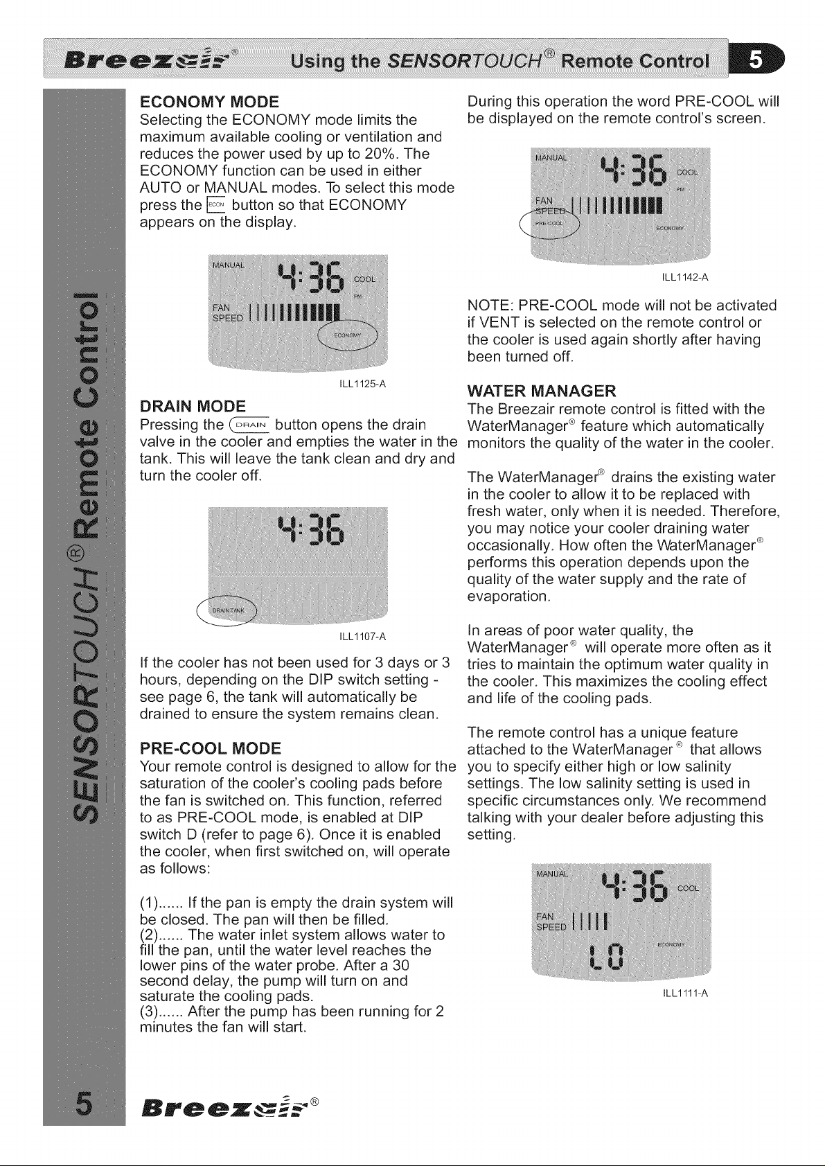
ECONOMY MODE
Selecting the ECONOMY mode limits the
maximum available cooling or ventilation and
reduces the power used by up to 20%. The
ECONOMY function can be used in either
AUTO or MANUAL modes. To select this mode
press the E button so that ECONOMY
appears on the display.
During this operation the word PRE-COOL will
be displayed on the remote control's screen.
ILL1142-A
NOTE: PRE-COOL mode will not be activated
if VENT is selected on the remote control or
the cooler is used again shortly after having
been turned off.
ILL1125-A
DRAIN MODE
Pressing the (..... button opens the drain
valve in the cooler and empties the water in the
tank. This will leave the tank clean and dry and
turn the cooler off.
ILL1107-A
If the cooler has not been used for 3 days or 3
hours, depending on the DIP switch setting -
see page 6, the tank will automatically be
drained to ensure the system remains clean.
PRE-COOL MODE
Your remote control is designed to allow for the
saturation of the cooler's cooling pads before
the fan is switched on. This function, referred
to as PRE-COOL mode, is enabled at DIP
switch D (refer to page 6). Once it is enabled
the cooler, when first switched on, will operate
as follows:
WATER MANAGER
The Breezair remote control is fitted with the
WaterManager ® feature which automatically
monitors the quality of the water in the cooler.
The WaterManager ® drains the existing water
in the cooler to allow it to be replaced with
fresh water, only when it is needed. Therefore,
you may notice your cooler draining water
occasionally. How often the WaterManager ®
performs this operation depends upon the
quality of the water supply and the rate of
evaporation.
In areas of poor water quality, the
WaterManager ® will operate more often as it
tries to maintain the optimum water quality in
the cooler. This maximizes the cooling effect
and life of the cooling pads.
The remote control has a unique feature
attached to the WaterManager ® that allows
you to specify either high or low salinity
settings. The low salinity setting is used in
specific circumstances only. We recommend
talking with your dealer before adjusting this
setting.
(1) ...... If the pan is empty the drain system will
be closed. The pan will then be filled.
(2) ...... The water inlet system allows water to
fill the pan, until the water level reaches the
lower pins of the water probe. After a 30
second delay, the pump will turn on and
saturate the cooling pads.
(3) ...... After the pump has been running for 2
minutes the fan will start.
ILL1111-A
 Loading...