

Seeley ATH15ST, ATH20ST, ATH20UT, ATH25UT, ATH30UT Installation, Operation & Service Manual
...
WARNING
Improper installation, adjustment, alteration, service
or maintenance can result in death, injury or
property damage. Read the installation, operation
and service manual thoroughly before installing or
servicing this equipment.
Installation must be done by a registered installer/
contractor qualified in the installation and service
of gas-fired heating equipment or your gas supplier.
Installer
Please take the time to read and understand
these instructions prior to any installation.
Installer must give a copy of this manual to the owner.
Owner
Keep this manual in a safe place in order to provide
your service technician with necessary information.
AIRA ATH
ATH15UT
ATH15ST
ATH30DL
ATH20UT
ATH20ST
ATH40DL
ATH25UT
ATH25ST
ATH50DL
ATH30UT
ATH30ST
ATH60DL
ATH35UT
ATH35ST
ATH70DL
ATH40UT
ATH40ST
ATH45UT
ATH45ST
ATH50UT
ATH50ST
FOR YOUR SAFETY
If you smell gas:
1.
Open windows.
2.
DO NOT try to light any appliance.
3.
DO NOT use electrical switches.
4.
DO NOT use any telephone in
your building.
5.
Extinguish any open flame.
6.
Leave the building.
7.
Immediately call your local gas
supplier after leaving the building.
Follow the gas supplier’s
instructions.
8.
If you cannot reach your gas
supplier, call the Fire Department.
WARNING
Fire Hazard
Keep all flammable objects, liquids and
vapors the minimum required clearances to combustibles away from
heater.
Some objects will catch fire or explode
when placed close to heater.
Failure to follow these instructions can
result in death, injury or property
damage.
Vacuum Assisted
Linear, Double Linear,
U-Tube, and Multi-Burner
Gas Fired Heating Systems
Installation, Operation &
Service Manual
© 2014 Roberts-Gordon LLC
Aira Pty Ltd
144 Colchester Road
Kilsyth, VIC 3137
Telephone: +61 3 9839 8000
Fax: +61 3 9761 4732
Email: sales@aira.com.au
www.aira.com.au
AH170106AU Orig 09/14

TABLE OF CONTENTS
All rights reserved. No part of this work covered by the copyrights herein may be reproduced
or copied in any form or by any means - graphic, electronic, or mechanical, including
photocopying, recording, taping or information storage and retrieval systems - without the
written permission of Roberts-Gordon Europe Limited.
© 2014 Roberts-Gordon Europe Limited
SECTION 1: Heater Safety............................................ 2
1.1 Manpower Requirements.................................... 2
1.2 Safety Labels and Their Placement .................... 2
SECTION 2: Installer Responsibility ........................... 4
2.1 Low Level User Instructions ............................... 4
2.2 Corrosive Chemicals .......................................... 4
2.3 National Standards and Applicable Codes ......... 4
SECTION 3: Clearances to Combustibles .................. 5
3.1 Required Clearances to Combustibles............... 5
3.2 Clearance Data - Linear and Double Linear ....... 6
3.3 Clearance Data -U Tube ........................................... 8
SECTION 4: Major Component Descriptions ............10
SECTION 5: General Suspension Details .................. 11
SECTION 6: Linear & Double Linear Heater
Installation ............................................. 13
6.1 Linear Standard Parts List ................................ 13
6.2 Double Linear Standard Parts List ....................16
SECTION 7: U-Tube Heater Installation .................... 25
7.1 U-Tube Standard Parts List ............................... 25
SECTION 8: Multiburner Configuration &
Installation ............................................. 34
8.1 Initial Assembly ................................................ 34
SECTION 9: Burner & Fan Installation ...................... 36
9.3 Linear & U-Tube Fan Installation ...................... 37
SECTION 10: Optional Heater Accessories .............. 40
10.1 Reflector Side Extension Installation .............. 41
10.2 U-Tube Cover Installation ............................... 42
10.3 Decorative Grille Installation ........................... 43
10.4 Protective Grille Installation ............................ 44
10.5 Sports Hall Guard Installation ........................ 45
10.6 Undershield Installation .................................. 46
10.7 Wall Mounting ................................................. 47
SECTION 11: Venting .................................................. 49
11.1 General Venting Requirements ....................... 49
11.2 Ventilation Requirements ................................ 49
11.3 Outside Combustion Air Supply ...................... 50
11.4 Common Duct ................................................. 51
SECTION 12: Gas Piping ............................................ 52
SECTION 13: Wiring.................................................... 54
13.1 Typical External Wiring Diagram
(Linear or U-Tube) .............................................. 54
13.2 Typical External Wiring Diagram
(Double Linear Option 1) ................................ 54
13.3 Typical External Wiring Diagram
(Double Linear Option 2) ................................ 55
13.4 Typical External Wiring Diagram
(Multiburner) ................................................... 55
13.5 Internal Wiring Diagram.................................. 56
SECTION 14: Operation .............................................. 57
14.1 Heater Lockout Indication (Optional) .............. 57
14.2 Testing .................................................................. 58
14.3 Commissioning (Multiburner) ......................... 58
System Checks ............................................... 58
14.5 User Instructions ............................................. 58
SECTION 15: Servicing Instructions ......................... 60
15.1 Annual Procedure ............................................. 60
15.2 Component Removal ...................................... 60
15.3 Maintenance Checklist ................................... 61
SECTION 16: Troubleshooting .................................. 63
16.1 Troubleshooting Flow Chart
(Linear, Double Linear and U-Tube) ................ 64
16.2 Troubleshooting Flow Chart (Multiburner) ....... 66
16.3 Manifold Gas Pressure Setting ....................... 68
SECTION 17: Replacement Parts .............................. 69
SECTION 18: Specifications ...................................... 71
18.1 Material Specifications.................................... 71
18.2 Heater Specifications...................................... 71
18.3 Venting Specifications .................................... 71
18.4 Suspension Specifications ............................. 71
18.5 Controls Specifications ................................... 71
18.6 Environment ................................................... 71
18.7 Linear Heater .................................................. 72
18.8 Double Linear Heater ..................................... 72
18.9 U-Tube Heater ................................................ 72
18.10 Burner Specifications .................................... 73
14.4
Printed in U.K.

TABLE OF FIGURES
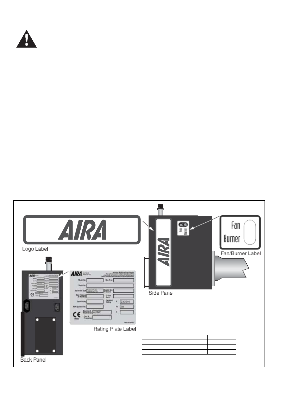
Figure 1: Side and Back Panel Label Placement ............ 2
Figure 2: Top Panel Label Placement ............................. 3
Figure 18: Critical Hanger Placement ........................... 12
Figure 19: Linear General Assembly Overview ..............14
Figure 20: Linear Layout Overview ............................... 15
Figure 21: Double Linear General Assembly Overview 17
Figure 22: Double Linear Layout Overview ................... 18
Figure 23: U-Tube Assembly Overview ......................... 26
Figure 24: U-Tube Layout Overview .............................. 27
Figure 25: Multiburner Damper Flange Installation ....... 34
Figure 26: Typical Manifold Layout (Linear and U-Tube
Configuration) .............................................. 35
Figure 27: U-Tube (Horizontal) ...................................... 47
Figure 28: U-Tube (Angle Mounted) .............................. 48
Figure 29: Linear ........................................................... 48
Figure 30: Individual Flue Connection Detail ................ 50
Figure 31: Flue Connection Dimensions ....................... 50
Figure 32: Fresh Air Intake Spigot ................................. 51
Figure 33: Air Supply with Flue Configurations ............. 51
Figure 34: Gas Connection with Stainless Steel Flex
Connector .................................................... 53
Figure 35: Sequence of Operation Chart ...................... 57
Figure 36: Burner Cup Position ..................................... 60
Figure 37: Linear and U-Tube Specifications ................ 73

ROBERTS GORDON® equipment has been tested and CE certified as complying with the essential
requirements of the Gas Appliance Directive, the Low Voltage Directive, the Electromagnetic
Compatibility Directive and the Machinery Directive for use on natural gas and LPG when installed,
commissioned and maintained in accordance with these instructions.
These instructions refer to appliances designed to operate in the European Union.
Appliances designed for other countries (Non-European Union) are available on request.
This appliance must be installed in accordance with the local and national codes in force and used
only in a sufficiently ventilated space, as specified in these instructions.
Before installation, check that the local gas distribution systems, nature of gas and pressure, and
adjustment of the appliance are compatible.
Product Approval
1 of 73
AIRA ATH INSTALLATION OPERATION AND SERVICE MANUAL
Description
Part Number
Logo Label
91033207
Fan/Burner Label
91033300
Rating Plate Label
91031300-AH
SECTION 1: HEATER SAFETY
Your Safety is Important to Us!
This symbol is used throughout the manual
to notify you of possible fire, electrical or burn
hazards. Please pay special attention when
reading and following the warnings in these
sections.
Installation, service and annual inspection of heater must
be done by a registered installer/contractor qualified in
the installation and service of gas-fired heating
equipment.
Read this manual carefully before installation, operation
or service of this equipment.
This heater is designed for heating nonresidential indoor
spaces. Do not install in residential spaces. These
instructions, the layout drawing, local codes and
ordinances, and applicable standards that apply to gas
piping, electrical wiring, venting, etc., must be thoroughly
understood before proceeding with the installation.
Protective gear is to be worn during installation, operation
and service. Thin sheet metal parts, such as the reflector
portion of the heater and the various venting
components, have sharp edges. To prevent injury, the use
of work gloves is recommended. The use of gloves will
also prevent the transfer of body oils from the hands to
the surface of the reflector.
Before installation, check that the local distribution
conditions, nature of gas and pressure, and adjustment of
the appliance are compatible.
The heater must be applied and operated under the
general concepts of reasonable use and installed using
best building practices.
This equipment is not intended for use by persons
(including children) with reduced physical, sensory or
mental capabilities, or lack of experience and knowledge,
unless they have been given supervision or instruction
concerning use of the appliance by a person responsible
for their safety. Children should be supervised to ensure
that they do not play with the appliance.
For additional copies of the Installation, Operation and
Service Manual, please contact Aira.
1.1
Manpower Requirements
To prevent personal injury and damage to the heater, two
persons will be required for installation.
1.2
Safety Labels and Their Placement
Product safety signs or labels should be replaced by the
product user when they are no longer legible. Contact
Aira for obtaining replacement signs or labels. See Page
2, Figure 1 through Page 3, Figure 2.
Figure 1: Side and Back Panel Label Placement
2 of 73
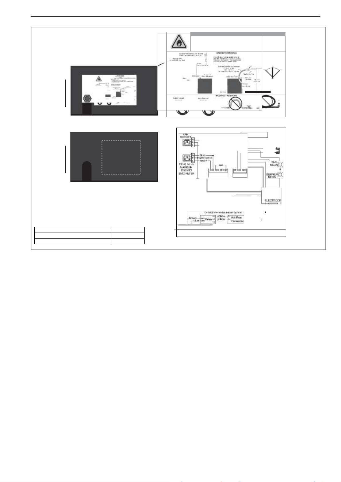
Figure 2: Top Panel Label Placement
INT ERNAL WIRING DIAGRAM
brown -- 1lkout Indicator
- blue - - 2Connector
blue
PRESSURE
black
SWITCH
white
•
Y
l : =iE;:--
AUT OMA TI C CO NTR OL UNI T
EARTH STUD
iii!
GAS VALVE
purple 1- --""'""'-'
Optional Voll Free Connecter
If
any of the or ginal wire
supplied with the heater must
be replaced, it must be
replaced w th wiring material
having a temperature rating of
at least 105 °C and 600 V.
P/ N 9103 1 40 1 Rev. M
AWARNING
Fire Ha zard
Tighten end install gae hoee fittings to connect gae eupply eccortling to example below.
Gae hoee can crack when twist ed.
Gae hoee moves during normal operation.
Uee only 1000 mm long connector of 112" or 314" nominal I
□.
Failure to !allow theee Instructions can result In death , Injury or property damage.
ShuHJ!lva
\'l!rticll
(loclLD! llW lli lias Hos!r)
(asSM 'Wfll elt)
1:
-·
Description
Part Number
Gas Connection Label
91018126
Internal Wiring Label
91031401
O=
SECTION 1: HEATER SAFETY
:
°'=
O=
Top Panel
Gas Connection Label
/
Top Panel - Inside Door
Internal Wiring Label
3 of 73
AIRA ATH INSTALLATION OPERATION AND SERVICE MANUAL
CAUTION
Product Damage Hazard
Do not use heater in area containing
corrosive chemicals.
Refer to appropriate Material Safety Data
Sheets (MSDS).
Failure to follow these instructions can result
in product damage.
SECTION 2: INSTALLER RESPONSIBILITY
To install the heater, as well as the gas and electrical
supplies, in accordance with applicable specifications
and codes. Aira recommends the installer contact a
local Building Inspector or Fire
Marshal for guidance.
To use the information given in a layout drawing and
in the manual together with the cited codes and
regulations to perform the installation.
To install the heater in accordance with the clearances to combustibles.
To furnish all needed materials not furnished as
standard equipment.
To plan location of supports.
To provide access to burners for servicing on all
sides, for burner removal.
To provide the owner with a copy of this installation,
operation and service manual.
To never use heater as support for a ladder or other
access equipment and never hang or suspend anything from heater.
To ensure there is adequate air circulation around the
heater and to supply air for combustion, ventilation
and distribution in accordance with local codes.
To safely and adequately install heater using materials with a minimal working load of 33 kg.
To ensure the heater is placed in an approved
application.
2.1
Low Level User Instructions
In all situations, clearances to combustibles must be
maintained. Signs should be posted in storage areas to
specify the maximum stacking height of items placed
below heater to maintain required clearances to
combustibles. Minimum clearances must be maintained
from vehicles parked below the heater. Caution should be
used when running the system near combustible
materials such as wood, paper, rubber, etc. Consideration
should be given to partitions, storage racks, hoists,
building construction, etc.
A laminated wall tag is available for the heater as a
permanent reminder of the safety instructions and the
importance of the required clearances to combustibles.
Please contact Aira or your Aira independent distributor to
obtain the wall tag. Affix the tag by peeling off the backing
of the adhesive strips on the rear surface and position the
tag on a wall near the heater (e.g. thermostat).
A copy of the wall tag (P/N 91037912-AH) is illustrated on
the back cover. This copy of the wall tag can be affixed on
the wall near the heater. Know your model number and
installed configuration. Model number and installed
configuration are found on the burner and in the
Installation, Operation and Service Manual. Write the
largest clearance dimensions with permanent ink
according to your model number and configuration in the
open spaces on the tag.
2.2
Corrosive Chemicals
Aira cannot be responsible for ensuring that all
appropriate safety measures are undertaken prior to
installation; this is entirely the responsibility of the
installer. It is essential that the contractor, the subcontractor, or the owner identifies the presence of
combustible materials, corrosive chemicals or
halogenated hydrocarbons* anywhere in the premises.
* Halogenated Hydrocarbons are a family of chemical
compounds characterized by the presence of halogen
elements (fluorine, chlorine, bromine, etc.). These compounds are frequently used in refrigerants, cleaning
agents, solvents, etc. If these compounds enter the air
supply of the burner, the lifespan of the heater components will be greatly reduced. An outside air supply must
be provided to the burners whenever the presence of
these compounds is suspected. Warranty will be invalid
if the heater is exposed to halogenated hydrocarbons.
2.3
National Standards and Applicable Codes
All appliances must be installed in accordance with the
latest revision of the applicable standards and national
codes. This refers also to the electric, gas and venting
installation. Note: Additional standards for installations in
public garages, aircraft hangars, etc. may be applicable.
4 of 73
SECTION 3: CLEARANCES TO COMBUSTIBLES
3.1
Required Clearances to Combustibles
Clearances are the required distances that combustible
objects must be away from the heater to prevent fire
hazards. Caution should be used when running the
system near combustibles. Combustibles are materials,
which may catch on fire and include common items such
as wood, paper, rubber, fabric, etc. Maintain clearances
to combustibles at all times for safety.
Clearances for all heater models are located on Page 6,
Figure 3 through Page 9, Figure 17 in this manual. Check
the clearances on each burner for the model heater being
installed to make sure the product is suitable for your
application and the clearances are maintained. Read and
follow the safety guidelines below:
Keep petrol or other combustible materials including
flammable objects, liquids, dust or vapours away from
this heater or any other appliance.
Do not spray aerosols in the vicinity of this appliance.
The stated clearances to combustibles represents a
surface temperature of 50° C (90° F) above room
temperature. Building materials with a low heat tolerance (such as plastics, vinyl siding, canvas, tri-ply,
etc) may be subject to degradation at lower tempera-
adjacent materials are protected from degradation.
Maintain clearances from heat sensitive equipment
and workstations.
Maintain clearances from vehicles parked below the
heater.
Maintain clearances from swinging and overhead
doors, overhead cranes, vehicle lifts, partitions, storage racks, hoists, building construction, etc.
In locations used for the storage of combustible materials, signs must be posted to specify the
maximum permissible stacking height to maintain
required clearances from the heater to the combustibles. Signs must be posted adjacent to the heater
thermostat. In the absence of a thermostat, signs
must be posted in a conspicuous location.
SECTION 3: CLEARANCES TO COMBUSTIBLES
Consult local Building Inspector, Fire Insurance
Carrier or other authorities for approval of proposed
installation when there is a possibility of exposure to
combustible airborne materials or vapours.
Hang heater in accordance to the minimum
suspension requirements on Page 72, Section 18.7
through Section 18.9.
If the radiant tubes must pass through the building
structure, be sure that adequate sleeving and fire
stop is installed to prevent scorching and/or fire
hazard.
5 of 73
WARNING
Fire Hazard
Keep all flammable objects, liquids and
vapors the minimum required clearances to
combustibles away from heater.
Some objects will catch fire or explode when
placed close to heater.
Failure to follow these instructions can result
in death, injury or property damage.
AIRA ATH INSTALLATION OPERATION AND SERVICE MANUAL
FIGURE 3: LINEAR & DOUBLE LINEAR, HORIZONTAL MOUNTS
A
B
D
C
Model
ATH15ST
ATH30DL
ATH20ST
ATH40DL
ATH25ST
ATH50DL
ATH30ST
ATH60DL
ATH35ST
ATH70DL
ATH40ST
ATH45ST
ATH50ST
A 150
150 150
150 150
150 200
200
B 890
970 970
1020
1170
1220
1280
1330
C 1570
1650
1650
1780
1930
1970
2010
2080
D 890
970 970
1020
1170
1220
1280
1330
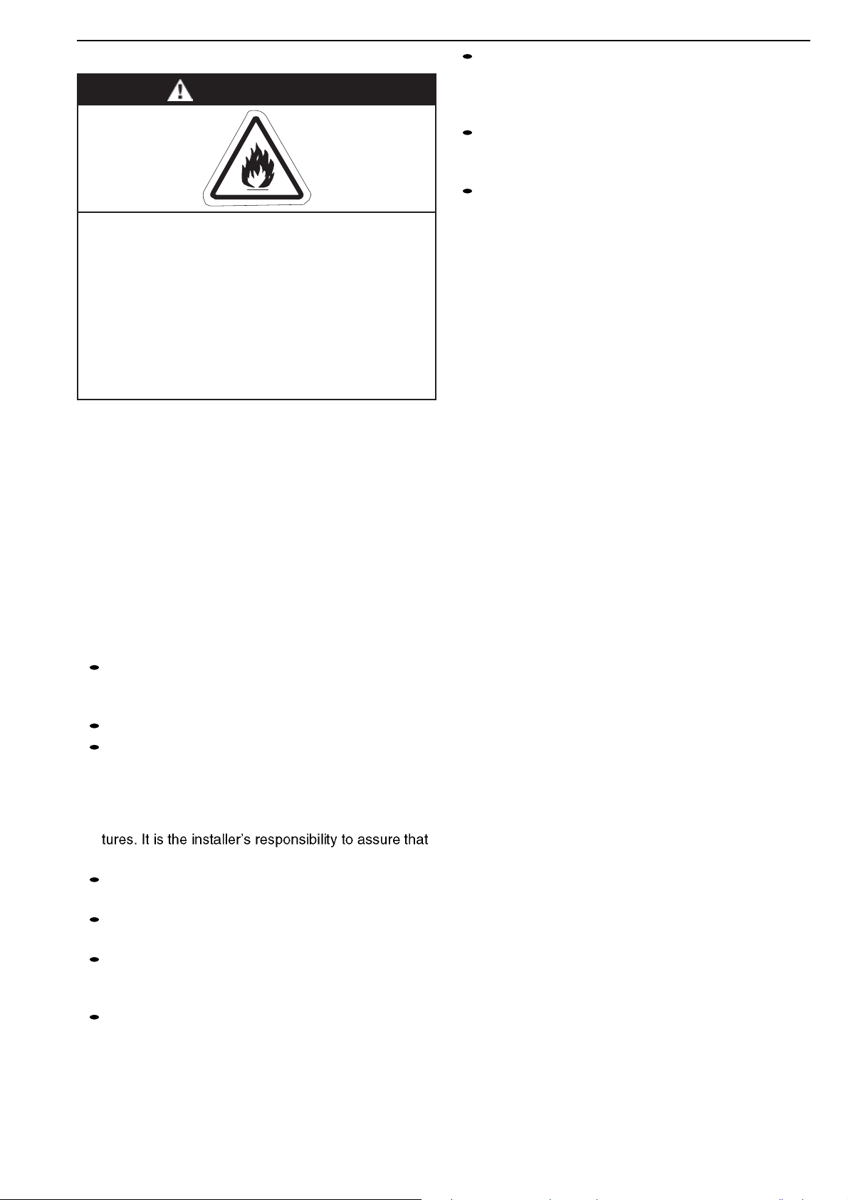
FIGURE 4: LINEAR & DOUBLE LINEAR, ONE SIDE REFLECTOR
A
B
D
C
Model
ATH15ST
ATH30DL
ATH20ST
ATH40DL
ATH25ST
ATH50DL
ATH30ST
ATH60DL
ATH35ST
ATH70DL
ATH40ST
ATH45ST
ATH50ST
A 150
150
150
150
150
150
200
200 B
230
230
230
230
230
230
230
230
C 1580
1760
1760
1930
2090
2130
2160
2240
D 1200
1380
1380
1500
1660
1710
1760
1860
FIGURE 5: LINEAR & DOUBLE LINEAR, TWO SIDE REFLECTORS
A
B
D
C
Model
ATH15ST
ATH30DL
ATH20ST
ATH40DL
ATH25ST
ATH50DL
ATH30ST
ATH60DL
ATH35ST
ATH70DL
ATH40ST
ATH45ST
ATH50ST
A 150
150
150
150
150
150
200
200
B 590
640
640
690
820
860
890
1020
C 1660
1810
1810
1960
2110
2160
2210
2320
D 590
640
640
690
820
860
890
1020
FIGURE 6: LINEAR & DOUBLE LINEAR, 45° MOUNT
A
C
B
D
Model
ATH15ST
ATH30DL
ATH20ST
ATH40DL
ATH25ST
ATH50DL
ATH30ST
ATH60DL
ATH35ST
ATH70DL
ATH40ST
ATH45ST
ATH50ST
A 200
200
200
250
250
275
300
300
B 200
200
200
200
200
200
200
200
C 1500
1660
1660
1860
1960
2030
2110
2160
D 1370
1520
1520
1630
1750
1820
1880
2000
3.2
Clearance Data - Linear and Double Linear
NOTE: 1. All dimensions are from the surfaces of all tubes, couplings, tees, elbows and crosses.
2.
Clearances B, C and D can be reduced by 50% after 7500 mm of tubing downstream
from the burner.
3.
All measurements are in millimeters.
* ATH55ST only available in multiburner.
6 of 73
SECTION 3: CLEARANCES TO COMBUSTIBLES
FIGURE 7: LINEAR & DOUBLE LINEAR, 2 FOOT DECO GRILLE
A
C
B
D
Model
ATH15ST
ATH30DL
ATH20ST
ATH40DL
ATH25ST
ATH50DL
ATH30ST
ATH60DL
ATH35ST
ATH70DL
ATH40ST
ATH45ST
ATH50ST
A 150
150
150
150
150
150
200
200 B
890
970
970
1020
1170
1220
1280
1330
C 1570
1650
1650
1780
1930
1970
2010
2080
D 890
970
970
1020
1170
1220
1280
1330
FIGURE 8: LINEAR & DOUBLE LINEAR, PROTECTIVE GRILLE
A
C
B
D
Model
ATH15ST
ATH30DL
ATH20ST
ATH40DL
ATH25ST
ATH50DL
ATH30ST
ATH60DL
ATH35ST
ATH70DL
ATH40ST
ATH45ST
ATH50ST
A 150
150
150
150
150
150
200
200
B 890
970
970
1020
1170
1220
1280
1330
C 1570
1650
1650
1780
1930
1970
2010
2080
D 890
970
970
1020
1170
1220
1280
1330
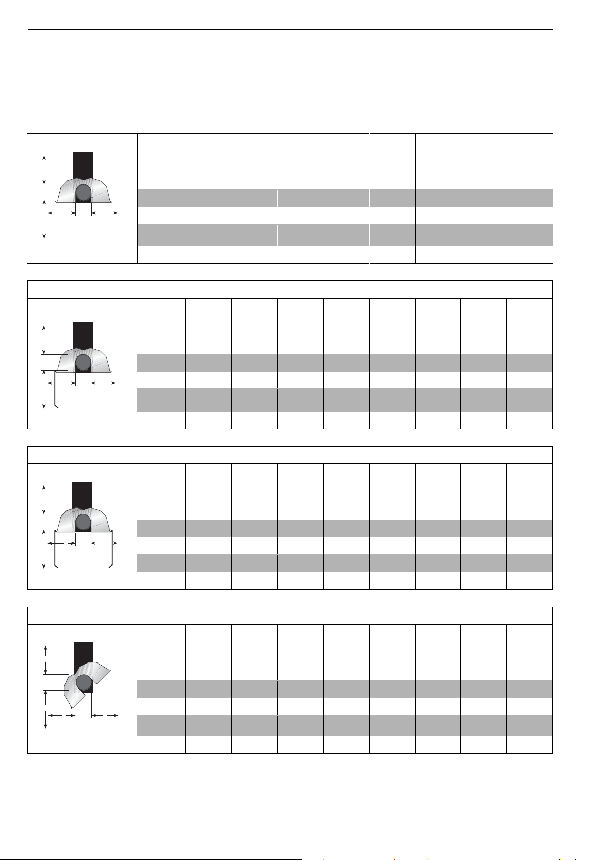
FIGURE 9: UNDERSHIELD **
A
B
D
C
Model
ATH15ST
ATH30DL
ATH20ST
ATH40DL
ATH25ST
ATH50DL
ATH30ST
ATH60DL
ATH35ST
ATH70DL
ATH40ST
ATH45ST
ATH50ST
A 150 150
150
150
150
150 - - B
990
1020
1270
1270
1370
1400 - -
C 840 965
1120
1120
1220
1270 - -
D 990
1020
1270
1270
1370
1400 - -
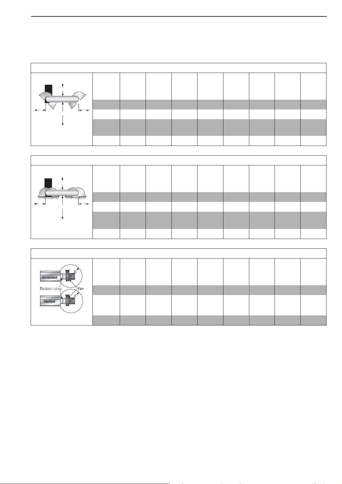
FIGURE 10: LINEAR & DOUBLE LINEAR, VENTING
Model
ATH15ST
ATH30DL
ATH20ST
ATH40DL
ATH25ST
ATH50DL
ATH30ST
ATH60DL
ATH35ST
ATH70DL
ATH40ST
ATH45ST
ATH50ST
E 1000
1000
1000
1000
1000
1000
1000
1000
F 500
500
500
500
500
500
500
500
NOTE: 1. All dimensions are from the surfaces of all tubes, couplings, tees, elbows and crosses.
2.
Clearances B, C and D can be reduced by 50% after 7500 mm of tubing downstream
from the burner.
3.
All measurements are in millimeters.
** When installed in the first 6 m - Not for use on EF models.
* ATH55ST only available in multiburner.
7 of 73
AIRA ATH INSTALLATION OPERATION AND SERVICE MANUAL
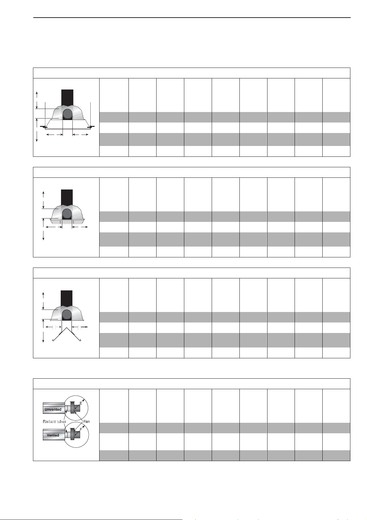
FIGURE 11: U-TUBE, HORIZONTAL MOUNT
A
B
D
C
Model
ATH15UT ATH20UT ATH25UT ATH30UT ATH35UT ATH40UT ATH45UT ATH50UT
A 150
150
150
150
150
150
200
200 B
890
970
970
1020
1170
1220
1270
1380
C 1580
1730
1730
1910
1980
2050
2110
2210
D 760
940
940
1000
1090
1150
1200
1300
FIGURE 12: U-TUBE, ONE SIDE REFLECTOR
A
B
D
C
Model
ATH15UT ATH20UT ATH25UT ATH30UT ATH35UT ATH40UT ATH45UT ATH50UT
A 150
150
150
150
150
150
200
200 B
230
230
230
230
230
230
230
230
C 1580
1760
1760
1930
2090
2130
2160
2240
D 1200
1380
1380
1500
1660
1710
1760
1860
FIGURE 13: U-TUBE, TWO SIDE REFLECTORS
A
B
D
C
Model
ATH15UT ATH20UT ATH25UT ATH30UT ATH35UT ATH40UT ATH45UT ATH50UT
A 150
150
150
150
150
150
200
200
B 590
640
640
690
820
860
890
1020
C 1660
1810
1810
1960
2110
2160
2210
2320
D 590
640
640
690
820
860
890
1020
FIGURE 14: U-TUBE, FULL 45° MOUNT
B
A
C
D
Model
ATH15UT ATH20UT ATH25UT ATH30UT ATH35UT ATH40UT ATH45UT ATH50UT
A 200
200
200
200
200
200
200
200
B 200
200
200
200
200
200
200
200
C 1500
1650
1650
1860
1960
2040
2110
2160
D 1070
1170
1170
1320
1550
1620
1680
1780
3.3
Clearance Data -U Tube
NOTE: 1. All dimensions are from the surfaces of all tubes, couplings, tees, elbows and crosses.
2.
Clearances B, C and D can be reduced by 50% after 7500 mm of tubing downstream
from the burner.
3.
All measurements are in millimeters.
4.
Add 60 mm clearance to uncovered U-tube.
8 of 73
SECTION 3: CLEARANCES TO COMBUSTIBLES
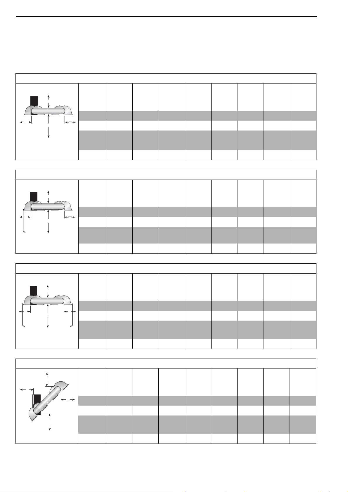
FIGURE 15: U-TUBE, OPPOSITE 45° TILT
A
B
D
C
Model
ATH15UT ATH20UT ATH25UT ATH30UT ATH35UT ATH40UT ATH45UT ATH50UT
A 200
200
200
250
250
275
300
300
B 1370
1530
1530
1630
1780
1830
1880
1930
C 1500
1650
1650
1860
1960
2040
2110
2160
D 560
560
560
560
560
560
560
560
FIGURE 16: U-TUBE, PROTECTIVE GRILLE
A
B
D
C
Model
ATH15UT ATH20UT ATH25UT ATH30UT ATH35UT ATH40UT ATH45UT ATH50UT
A 150
150
150
150
150
150
200
200
B 890
970
970
1020
1170
1220
1270
1380
C 1580
1730
1730
1910
1980
2050
2110
2210
D 760
940
940
1000
1090
1150
1200
1300
FIGURE 17: U-TUBE, VENTING
Model
ATH15UT ATH20UT ATH25UT ATH30UT ATH35UT ATH40UT ATH45UT ATH50UT
E 1000
1000
1000
1000
1000
1000
1000
1000
F 500
500
500
500
500
500
500
500
NOTE: 1. All dimensions are from the surfaces of all tubes, couplings, tees, elbows and crosses.
2.
Clearances B, C and D can be reduced by 50% after 7500 mm of tubing downstream
from the burner.
3.
All measurements are in millimeters.
4.
Add 60 mm clearance to uncovered U-tube.
9 of 73
AIRA ATH INSTALLATION OPERATION AND SERVICE MANUAL
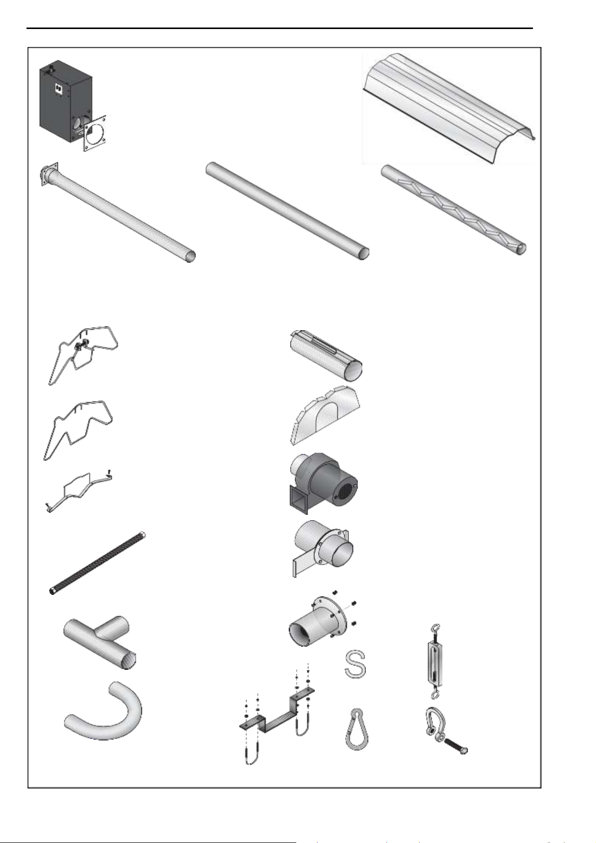
SECTION 4: MAJOR COMPONENT DESCRIPTIONS
Burner (shown with Tube
Gasket)
Must be installed with the
flame observation window
facing down.
Reflector
(Aluminium or
Stainless Steel)
Alternate overlap as
shown on overview.
Minimum overlap is
160 mm.
Burner Tube
Supplied in 3,000 mm lengths.
Burner tube is always the first
tube after the burner.
Tube
Heat treated aluminised tube
supplied in 3,000 mm lengths.
Fan Tube with Internal Swirler
Supplied in 3,000 mm lengths. Fan
tube is always the last tube on the
heater where the fan is attached.
The swirler is welded to the inside
Tube and Reflector Hanger
with Clamp Package
Position this hanger no more
than 100 mm away from the
burner assembly.
Tube and Reflector Hanger
Suspend system from these
hangers.
Reflector Support Strap, Wire
Form & #8 x 3/4 (3.9 x 19mm)
Screw
of the tube end.
Coupling Assembly
with Lock
Reflector End Cap
Punch out center section to
accommodate tube.
Fan Assembly (Includes Flange)
Fan Assembly is attached to the last
section of heat exchanger tubing
(Fan Tube).
Flex Gas Line
Damper Flange Assembly
For use on Multiburner Systems.
Tee
Assembly
Fan Flange Assembly
and Screws
S-hook
Height
Adjuster
U-Tube
U-Tube
Support
Bracket
Spring
Hook
Bow
Shackle
10 of 73
SECTION 5: GENERAL SUSPENSION DETAILS
WARNING
Severe Injury Hazard
Secure burner to burner tube with bolts and
lockwashers.
Hang heater with materials with a minimum
working load of 75 lbs (33 kg).
Failure to follow these instructions can result
in death, injury or property damage.
WARNING
Cut/Pinch Hazard
Wear protective gear during installation,
operation and service.
Edges are sharp.
Failure to follow these instructions can result
in injury.
SECTION 5: GENERAL SUSPENSION DETAILS
To ensure your safety, and comply with the terms of the
warranty, all units must be installed in accordance with
these instructions.
The gas or the electrical supply lines must not be used to
support the heater.
Do not locate the gas or electric supply lines directly over
the path of the flue products from the heater.
The heater must be installed in a location that it is readily
accessible for servicing.
The heater must be installed in accordance with
clearances to combustibles as indicated in this manual.
The minimum and maximum gas inlet pressures must be
maintained as indicated on the rating plate. Typical
installation configurations are shown on Page 12, Figure
18.
Suspension chain is not supplied as standard equipment.
Note: Some models will receive S-hooks (P/N 91907302)
or spring hooks (P/N 91903300), rather than bow
shackles.
11 of 73
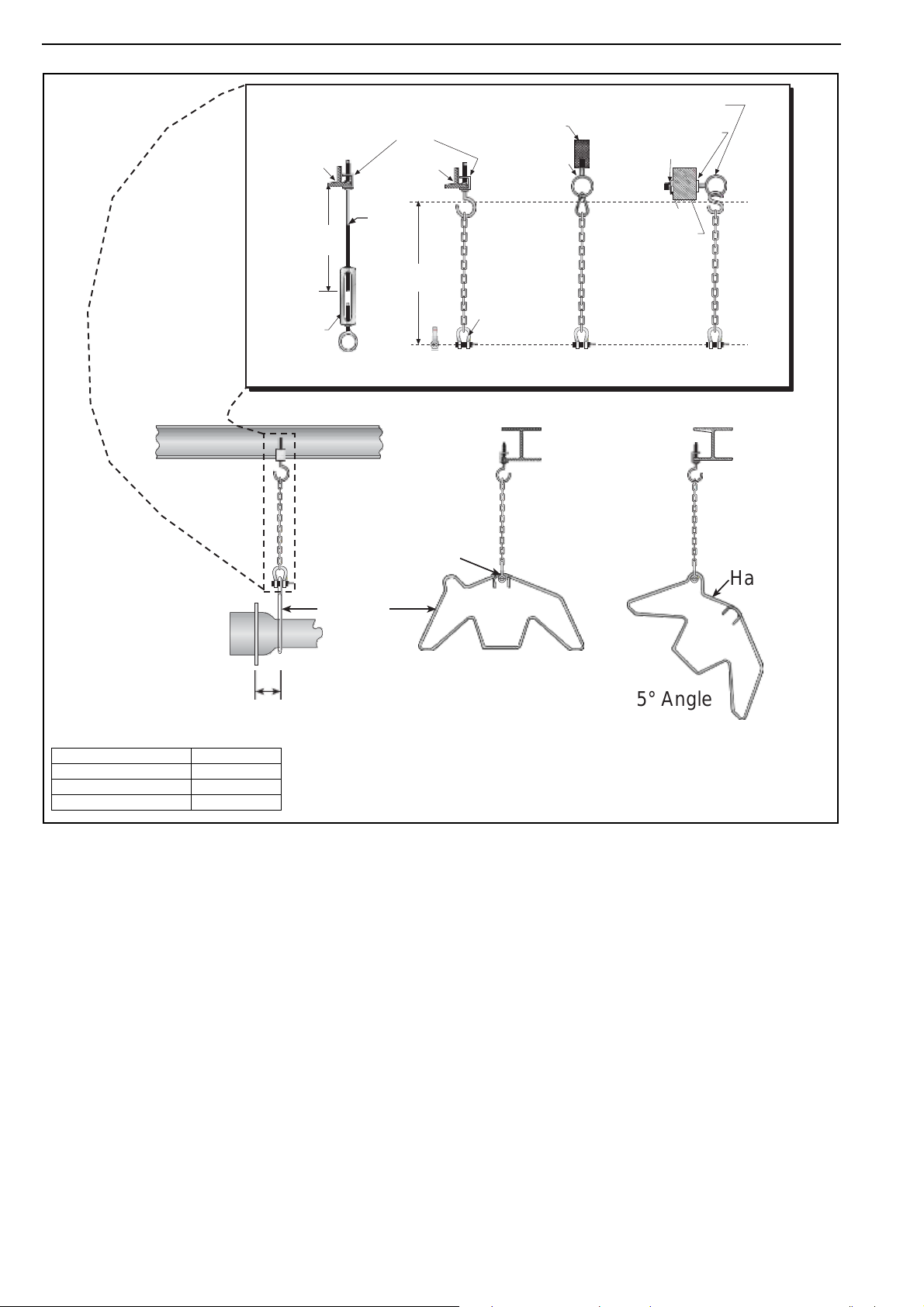
Typical Suspension Details
I-Beam
Beam
Clamp
I-Beam
Concrete
Beam
Anchor
Screw Hook
min. 10 mm
Washer
Locknut
600 mm
minimum*
10 mm
Rod
Washer
Wood
Beam
300 mm
minimum*
Bow
Shackle
Turnbuckle
(not included)
* Allows for thermal expansion of system.
Side View
Bow Shackle
Hanger
Hanger
100 mm
Max.
Front View
45° Angle
AIRA ATH INSTALLATION OPERATION AND SERVICE MANUAL
Figure 18: Critical Hanger Placement
Description
Part Number
Burner Tube
03051100
Bow Shackle
E0007576
Tube/Reflector Hanger
03090100
For suspension angles other than shown, additional chain supports may be required.
12 of 73
SECTION 6: LINEAR & DOUBLE LINEAR HEATER INSTALLATION
SECTION 6: LINEAR & DOUBLE LINEAR HEATER INSTALLATION
The figures in this section provide a general overview of
component placement in a Linear and Double Linear
system. The location of some components such as
supports and couplings is crucial for proper installation.
Assemble the heater components as shown on Page 14,
Figure 19.
For optional reflector configurations for linear heaters see
Page 6, Figure 3 through Page 7, Figure 10. Install
appropriate suspension hardware, beam clamps, chain or
rod at predetermined locations. Adjustments of chain
length will provide uniform pitch.
If any step is unclear, please contact Aira at +61 3 9839
8000.
6.1
Linear Standard Parts List
Part No.
Description
ATH15ST ATH20ST ATH25ST ATH30ST ATH35ST ATH40ST ATH45ST ATH50ST
ATH72XXXXX
Burner Assembly (Input and Fuel Varies)
1 1 1 1 1 1 1 1 07260001
Fan Package XP 1
1 1 1 1 - - - - 07260002
Fan Package XP2
- - - - 1 1 1 - 07260003
Fan Package XP 3
- - - - - - - 1 03051100
Burner Tube, 100 mm x 3048 mm
1 1 1 1 1 1 1 1 91409408
Tube, 100 mm x 3048 mm
- 1 1 2 2 2 3 3 S5127W
Fan Tube, 100 mm x 3048 mm, with 3048 mm Swirler
- 1 1 1 1 1 1 1 S5134W
Fan Tube, 100 mm x 3048 mm, with 2134 mm Swirler
1 - - - - - - - 01329600
Standard Coupling Assembly
1 2 2 3 3 3 4 4
01329700
Coupling Lock
1 2 2 3 3 3 4 4 02750303
Reflector, Aluminium, 2439 mm
3 4 4 6 6 6 7 7 027503SS
Reflector, Stainless Steel, 2439 mm (Optional)*
3 4 4 6 6 6 7 7 02750800
Reflector End Cap, Aluminium
2 2 2 2 2 2 2 2 027508SH
Reflector End Cap, Stainless (Optional)*
2 2 2 2 2 2 2 2 03090100
Tube and Reflector Hanger
3 4 4 5 5 5 6 6 01318901
Tube Clamp Package (including Nut, Washer & Bolt)
1 1 1 1 1 1 1 1 91908004
Wire Form
2 3 3 5 5 5 6 6 94320812
Screw #8 x 3/4 (3.9 mm x 19 mm), (goes with 03050000)
4 6 6 10 10 10 12 12 03050000
Reflector Support Strap
2 3 3 5 5 5 6 6 E0007576
Bow Shackle**
3 4 4 5 5 5 6 6
91107720
U-Clip Package (20 Pieces)
1 1 1 1 1 1 1 1 S7199K
Damper Flange Assembly (For use on Multiburner Systems)
1 Per Heater
* PVC coating must be removed prior to installation.
** Some models may receive S-hooks (P/N 91907302) or
spring hooks (P/N 91903300), rather than bow shackles.
13 of 73
WARNING
Cut/Pinch Hazard
Wear protective gear during installation,
operation and service.
Edges are sharp.
Failure to follow these instructions can result
in injury.
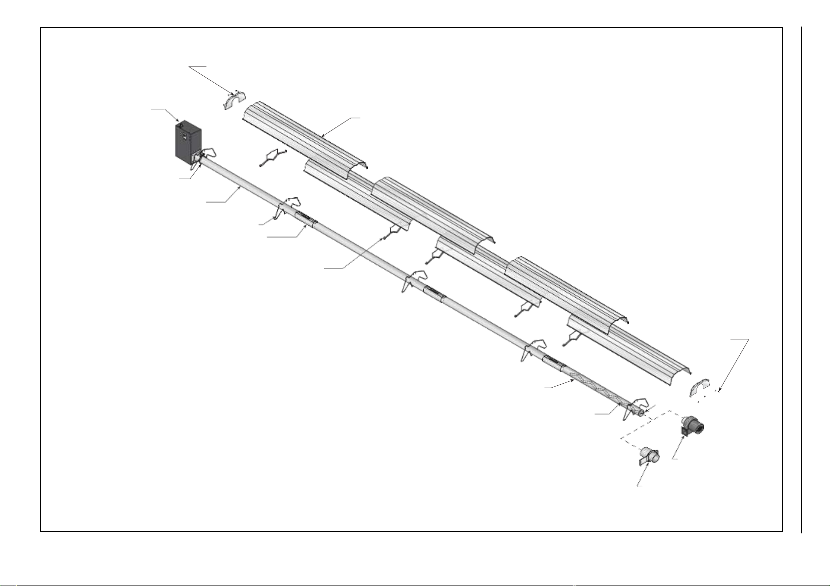
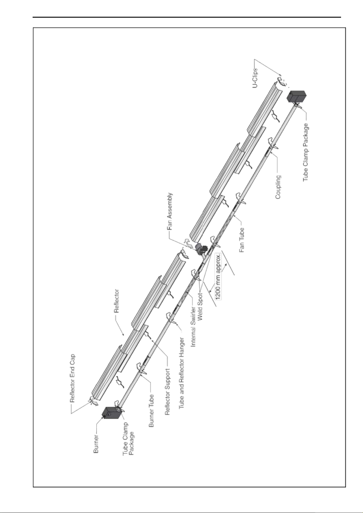
Reflector End Cap
Burner
Reflector
Tube Clamp Package
Burner Tube
Tube and Reflector Hanger
Coupling
Reflector Support
U-Clips
Fan Tube
Internal Swirler
Weld
Spot
Fan Assembly
(For Single Heater)
Damper Assembly
(Required for Multiburner)
AIRA ATH INSTALLATION OPERATION AND SERVICE MANUAL
Figure 19: Linear General Assembly
Overview
14 of 73
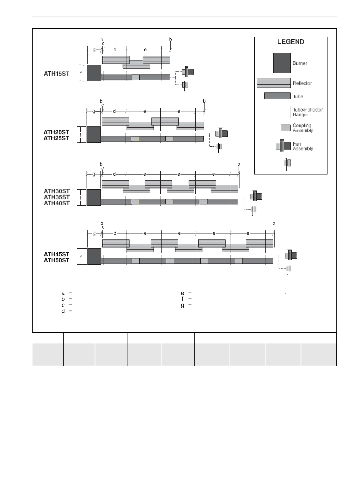
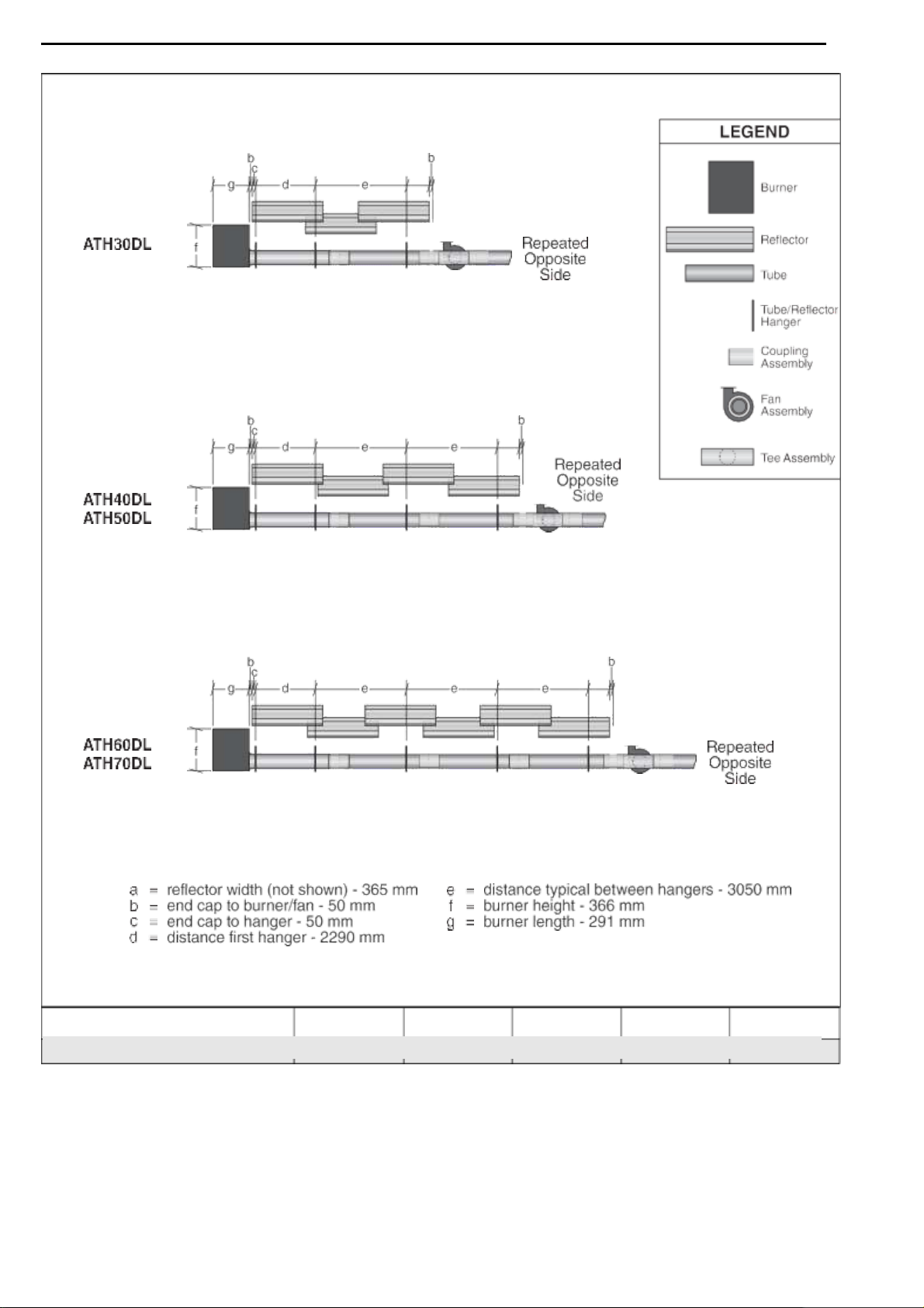
Figure 20: Linear Layout Overview
SECTION 6: LINEAR & DOUBLE LINEAR HEATER INSTALLATION
Model
ATH15ST
ATH20ST
ATH25ST
ATH30ST
ATH35ST
ATH40ST
ATH45ST
ATH50ST
Reflector
Overlap
(approx.)
700 mm
250 mm
250 mm
530 mm
530 mm
530 mm
330 mm
330 mm
15 of 73

AIRA ATH INSTALLATION OPERATION AND SERVICE MANUAL
Part No.
Description
ATH30DL ATH40DL ATH50DL ATH60DL ATH70DL
ATH72XXXXX
Burner Assembly (Input and Fuel Varies)
2 2 2 2 2 07260002
Fan Package XP2
1 1 - - - 07260003
Fan Package XP3
- - 1 1 1 03051100
Burner Tube, 100 mm x 3048 mm
2 2 2 2 2 91409408
Tube, 100 mm x 3048 mm
- 2 2 4 4 S5127W
Fan Tube, 100 mm x 3048 mm, with 3048 mm Swirler
- 2 2 2 2 S5134W
Fan Tube, 100 mm x 3048 mm, with 2134 mm Swirler
2 - - - - 01330203
Tee, 100 mm x 100 mm x 100 mm
1 1 1 1 1 01329600
Standard Coupling Assembly
4 6 6 8 8 01329700
Coupling Lock
4 6 6 8 8 02750303
Reflector, Aluminium, 2439 mm
6 8 8 12 12 027503SS
Reflector, Stainless Steel, 2439 mm (Optional)*
6 8 8 12 12 02750800
Reflector End Cap, Aluminium
4 4 4 4 4 027508SH
Reflector End Cap, Stainless (Optional)*
4 4 4 4 4
03090100
Tube and Reflector Hanger
6 8 8 10 10 01318901
Tube Clamp Package (including Nut, Washer & Bolt)
2 2 2 2 2 91908004
Wire Form
4 6 6 10 10 03050000
Reflector Support Strap
4 6 6 10 10 E0007576
Bow Shackle**
6 8 8 10 10 91107720
U-Clip Package (20 Pieces)
2 2 2 2 2 E0007582
Height Adjuster
6 8 8 10 10 94320812
Screw #8 x 3/4 (3.9 mm x 19 mm), (goes with 03050000)
8 12 12 20 20
6.2
Double Linear Standard Parts List
* PVC coating must be removed prior to installation.
**Some models may receive S-hooks (P/N 91907302) or
spring hooks (P/N 91903300), rather than bow shackles
16 of 73
SECTION 6: LINEAR & DOUBLE LINEAR HEATER INSTALLATION
Figure 21: Double Linear General Assembly Overview
17 of 73
AIRA ATH INSTALLATION OPERATION AND SERVICE MANUAL
Figure 22: Double Linear Layout Overview
Model
ATH30DL
ATH40DL
ATH50DL
ATH60DL
ATH70DL
Reflector Overlap (approx.)
700 mm
250 mm
250 mm
530 mm
530 mm
18 of 73
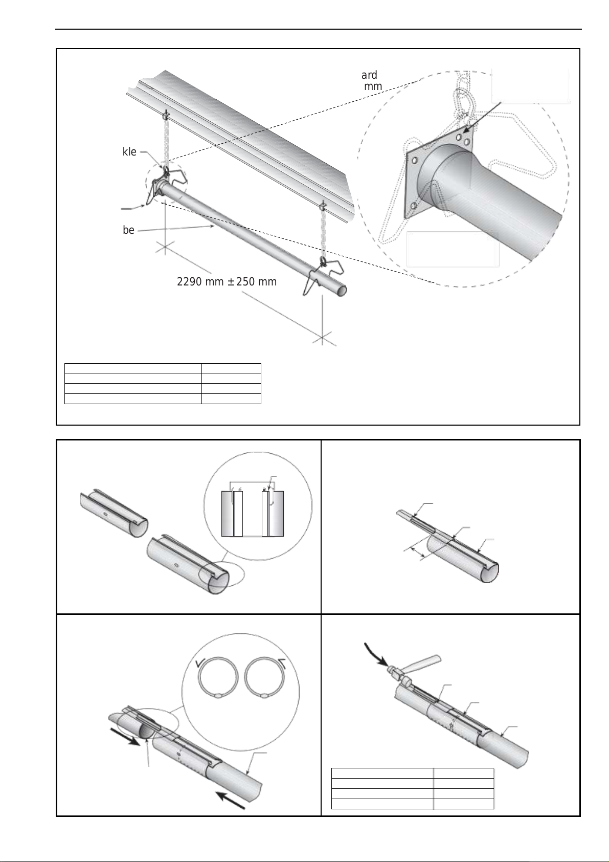
Note:
Tubing requires a downward
slope of 13 mm per 6000 mm
away from burner.
Offset mounting
hole must be
to the top.
Bow Shackle
Hanger
Burner Tube
Weld seam
must be to the
bottom of the tube.
2290 mm ± 250 mm
Step 6.3 Burner Tube Installation
Description
Part Number
Burner Tube
03051100
Bow Shackle
E0007576
Tube/Reflector Hanger
03090100
A
Close coupling
with tab.
Tab
Open
Closed
B
Start slide bar/coupling lock
onto coupling.
Slide Bar
Wide End
Coupling
76 mm to
101 mm
C
Insert tubes into coupling.
Orient coupling so that
the impact block is in the
2:00 or 10:00 o'clock
positions
Tube
Tube
D
Tighten coupling to join tubes.
Slide Bar
Coupling
Tube
Description
Part Number
Coupling
01329600
Slide Bar/Coupling Lock
01329700
Tube
91409408
SECTION 6: LINEAR & DOUBLE LINEAR HEATER INSTALLATION
Step 6.4 Coupling and Tube Assembly
19 of 73
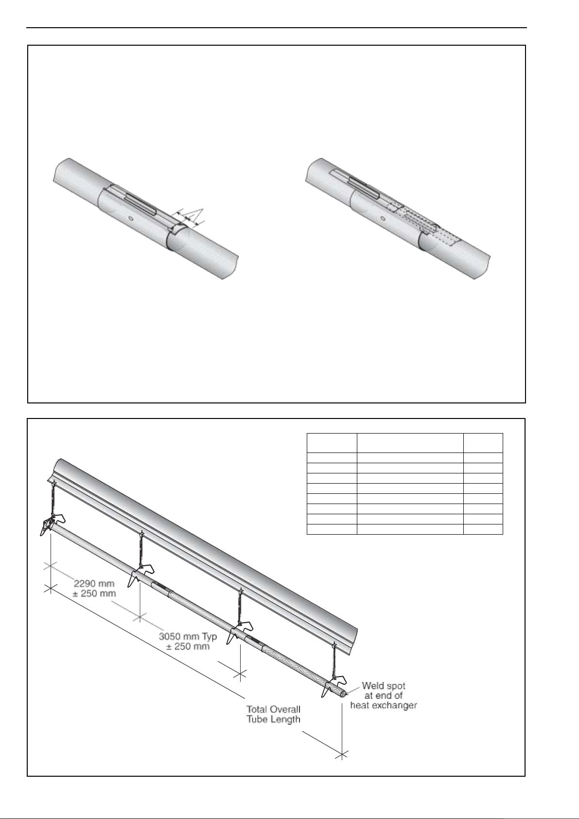
Incorrect Slide Bar
position
Correct Slide Bar
dimensions
± 50 mm
Drive slide bar until tight.
End of slide bar should be
within tolerance listed below.
AIRA ATH INSTALLATION OPERATION AND SERVICE MANUAL
Model
Overall Tube Length (mm)
Number
of Tubes
ATH15ST
6,000
2
ATH20ST
9,000
3
ATH25ST
9,000
3
ATH30ST
12,000
4
ATH35ST
12,000
4
ATH40ST
12,000
4
ATH45ST
15,000
5
ATH50ST
15,000
5
•
Repeat Step 6.4 A - D until all tubes are assembled. See Page 20, Section 6.4.2 shown below.
Tighten slide bar as shown below.
Step 6.4.1 Coupling and Tube Assembly (Continued)
Step 6.4.2 Coupling and Tube Assembly (Continued)
20 of 73
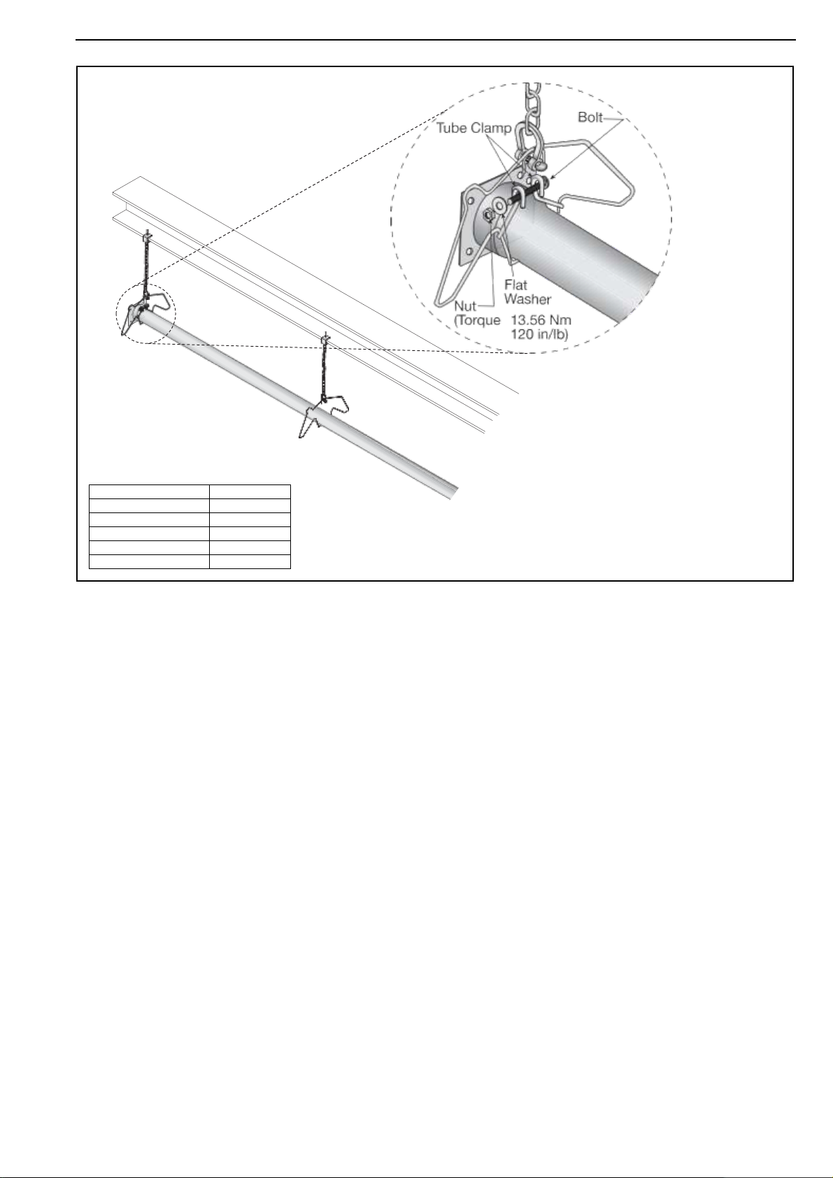
Note: Tube clamp package should be
installed 100 mm from burner tube plate.
Other hangers do not need tube clamp
packages.
Step 6.5 Tube Clamp Package Installation
Description
Part Number
Tube Clamp Package
01318901
Tube Clamp
01396801
Bolt
97113940
Flat Washer
95211600
Nut
92113900
SECTION 6: LINEAR & DOUBLE LINEAR HEATER INSTALLATION
21 of 73
 Loading...