

Page 1

T H E N E W G E N E R A T I O N L O R A W A N S E N S O R S O F S E N S E C A P
S2100 LoRaWAN Data Logger
User Guide
Version: v1.1.1
Page 2

Table of Contents
1. Product Introduction .......................................................................................4
2. Part List ............................................................................................................5
3. Quick Start .......................................................................................................6
3.1 Sensor Configuration Example .................................................................................. 6
4. Hook up the Sensor Probe ............................................................................. 7
4.1 Preparation................................................................................................................. 7
4.1.1 Sensor Probe ..................................................................................................................... 7
4.1.2 Tools .................................................................................................................................. 7
4.2 Connect the Sensor Probe ......................................................................................... 8
4.2.1 Disassemble the Data Logger ........................................................................................... 8
4.2.2 Power supply options of sensor .........................................................................................9
4.2.3 How to install external 12V DC ........................................................................................10
5. LED of Sensor Working Status .................................................................... 14
6. SenseCAP Mate App ..................................................................................... 16
6.1 Download App .......................................................................................................... 16
6.2 How to connect sensor to App ................................................................................. 17
6.2.1 Create a New Account .....................................................................................................17
6.2.2 Connect to Sensor to App ................................................................................................18
6.3 Configure basic parameters through App ................................................................ 20
6.3.1 Select the Platform and Frequency ................................................................................. 20
6.3.2 Set the Interval .................................................................................................................24
6.3.3 Set the EUI and Key ........................................................................................................ 24
6.3.4 Set the Packet Policy .......................................................................................................25
6.3.5 Set the Activation Type ....................................................................................................25
6.3.6 Restore Factory Setting ................................................................................................... 26
6.4 Configure Level or Pulse Sensor via App ................................................................ 27
6.4.1 Set the Level Mode ..........................................................................................................28
6.4.2 Set the Counter Mode ......................................................................................................28
6.5 Configure Analog Sensor via App ............................................................................31
6.5.1 Set the 4~20mA sensor ................................................................................................... 31
6.5.1 Set the 0~10V Voltage sensor .........................................................................................32
6.6 Configure RS485 Modbus-RTU Sensor via App ..................................................... 34
7. Connect to the SenseCAP Portal .................................................................37
7.1 SenseCAP Portal ......................................................................................................37
7.1.1 Create a New Account .....................................................................................................37
7.1.2 Other Functions ............................................................................................................... 37
7.1.3 API Instruction ..................................................................................................................38
Page 3

7.2 Connect to SenseCAP with Helium Network ...........................................................39
7.2.1 Quick Start ....................................................................................................................... 39
7.2.2 Preparation ...................................................................................................................... 39
7.2.3 Bind Sensor to SenseCAP Portal .................................................................................... 40
7.2.4 Setup the Sensor ............................................................................................................. 42
7.2.5 Set Frequency of Sensor via SenseCAP Mate App ........................................................43
7.2.6 Check Data on SenseCAP Portal ....................................................................................44
7.3 Connect to SenseCAP with private TTN ..................................................................46
7.3.1 Quick Start ....................................................................................................................... 46
7.3.2 Preparation ...................................................................................................................... 46
7.3.3 Bind Sensor to SenseCAP Portal .................................................................................... 47
7.3.4 Setup the Sensor ............................................................................................................. 48
7.3.5 Set Frequency of Sensor via SenseCAP Mate App ........................................................48
7.3.6 Check Data on SenseCAP Portal ....................................................................................49
8. Connect to Helium Network ......................................................................... 50
9. Connect to The Things Network .................................................................. 50
10. Payload Decoder ......................................................................................... 51
10.1 Decoder Code ........................................................................................................ 51
10.2 Packet Parsing ....................................................................................................... 52
10.2.1 Packet Initialization ........................................................................................................52
10.3 Data Parsing Example ............................................................................................54
10.3.1 Example - one measurement ........................................................................................ 54
10.3.2 Example - two measurements ....................................................................................... 54
10.3.3 Example - four measurements ...................................................................................... 55
10.3.4 Example - six measurements ........................................................................................ 56
10.3.5 Battery Information ........................................................................................................ 57
11. LoRaWAN Downlink Command ................................................................. 59
11.1 Set the Data Uplink Interval ................................................................................... 59
11.2 Reboot the device ...................................................................................................60
11.3 How to send downlink ............................................................................................ 60
12. Device Installation .......................................................................................62
12.1 Check the waterproof performance of the device ..................................................62
12.1.1 Data logger connection port .......................................................................................... 62
12.1.2 Waterproof check ...........................................................................................................62
12.2 Installing Sensor ..................................................................................................... 62
12.2.1 Installing the Sensor Bracket .........................................................................................62
12.2.1 Mount on Pole and Wall .................................................................................................64
12.3 Replace the Battery ................................................................................................66
12.3.1 How to Buy the Battery ..................................................................................................66
12.3.2 How to Replace a New Battery ......................................................................................67
Page 4

13. Trouble Shooting ........................................................................................ 69
13.1 Sensors can’t join LoRa network, how to do? ........................................................69
13.2 Why is the new sensor’s battery not 100%? ..........................................................69
13.3 Support................................................................................................................... 69
13.4 Document Version ..................................................................................................69
Page 5

IoT into the Wild
1. Product Introduction
S2100 LoRaWAN Data Logger can collect data from different types of sensors and transfer
the data through LoRaWAN network. If you have deployed sensors that are not based on the
LoRaWAN network, then with our LoRaWAN Data Logger, you can change them into
LoRaWAN-based sensors and use the LoRaWAN network to transfer data. You can easily
enjoy the advantages of LoRaWAN technology such as low power consumption and long
transmission range, without affording the cost of changing the sensors you are using.
4
Page 6

IoT into the Wild
Picture
Name
Quantity
Data Logger
1
Bracket
1
Quick Start Guide
1
KA4*20mm Self-drilling Screw
4
Picture
Name
Quantity
Junction box
1
8 pin wire (40cm)
1
Waterproof adhesive tape
1
2. Part List
Before installing, please check the part list to ensure nothing is missing.
A junction box accessory kit is available as an additional option, and be ordered separately:
5
Page 7

IoT into the Wild
Step
Description
Section
1
Hook up the sensor probe
Section 4
2
Download SenseCAP Mate App
Section 6.1
3
Configure the LoRaWAN parameters
Section 6.3
4
Configure the sensor protocol
Section 6.4 for level / pulse
sensor
Section 6.5 for analog sensor
Section 6.6 for RS485 sensor
5
Join LoRaWAN network server
Section 7.2 or 7.3
6
Check the data on the SenseCAP Dashboard
and SenseCAP Mate App
Section 7.2.6
7
Deploying sensors
Section 12
3. Quick Start
Refer to the following steps for quick configuration with SenseCAP server.
3.1 Sensor Configuration Example
TBD
6
Page 8

IoT into the Wild
Type
Sensor wire pin
RS485 Modbus-RTU
1 x A, 1 x B, 1 x GND, 1 x VCC
4~20 mA
1 or 2 x signal pin
0~10V
1 or 2 x signal pin
Level
1 x signal pin
Pulse Count
1 x signal pin
Note:
Each Data logger can only be connected to one type of sensor. For example
1. a RS485 sensor with one address
2. a 4~20mA sensor with 1or 2 measurements
3. a 0~10V (Less than 10v) sensor with 1or 2 measurements
4. a pulse or level sensor with 1 measurement
Type
Description
Cross screwdriver
Cross recess No.2
4. Hook up the Sensor Probe
4.1 Preparation
4.1.1 Sensor Probe
Get one of these sensors ready:
4.1.2 Tools
7
Page 9

IoT into the Wild
4.2 Connect the Sensor Probe
4.2.1 Disassemble the Data Logger
1. Unscrew three screws.
2. Take down the cover.
3. Remove the thread cap and pass it through the cable of the sensor, pass it through
the bottom cover, and connect it to the wiring terminal.
8
Page 10

IoT into the Wild
No.
Pin
Description
1
12V
External 12V input voltage. The Data Logger can be
powered by an external 12V DC power supply.
When using 12V power supply, the battery will serve as
backup power supply.
25V5V output voltage, providing 5V voltage to the sensor.
33V3V output voltage, providing 3V voltage to the sensor.
4IOAcquisition level or pulse input
5V1Analog voltage input ranges from 0 to 10V
6V2Analog voltage input ranges from 0 to 10V
7ARS485 A/+
8BRS485 B/-
9I1Analog current input ranges from 4 to 20mA
10I2Analog current input ranges from 4 to 20mA
11
GND
Ground
12
GND
Ground
Mode
Description
Built-in Battery
When the Data Logger and sensors only powered by internal
battery. The datalogger only support 5V or 3V sensor probes.
External 12V DC
If some cases, the sensor probe needs a higher power source
which the internal battery cannot last for long time.
An external 12V power source could be the main power supply,
and the internal battery works as a backup power source when
the 12V power outage happen.
When using external 12V power supply, it is recommended that
working together with the junction box to make sure the
waterproof covered.
4.2.2 Power supply options of sensor
Data Logger supports two power supply modes:
9
Page 11

IoT into the Wild
4.2.3 How to install external 12V DC
When your sensor needs 12V power, the internal battery will not be able to feed the sensor.
Therefore, an external 12V power supply is required.
Take the SenseCAP ONE Weather Station as an example.
1) Prepare the12V DC adapter, Junction box, and 4-pin wire.
2) Wire the RS485-A, RS485-B and GND and external 12V input to the green terminal.
Definition of the cable:
10
Page 12

IoT into the Wild
Wire color
The pin of Data Logger
Red
12V
Black
GND
Yellow
A
Blue
B
3) Put the device circuit board back to enclosure, and make sure the waterproof rubber is
well assembled.
4) Wire to the terminal of the junction box.
11
Page 13

IoT into the Wild
5) Connect the sensor wire to the junction box.
6) Connect the 12V DC adapter to the power supply.
7) To complete the assembly.
12
Page 14

IoT into the Wild
8) Tighten the screws and screw caps to check the waterproofing. If the wire diameter
is too thin, add waterproof tape for winding.
*Note: When assembling the device, it is necessary to install the waterproof pad of the Data
Logger and the adapter box, and tighten the screw cap and screw, otherwise the waterproof
effect of the device may be affected!
If the wire diameter is too small, it can be wrapped with waterproof tape, as shown below:
13
Page 15

IoT into the Wild
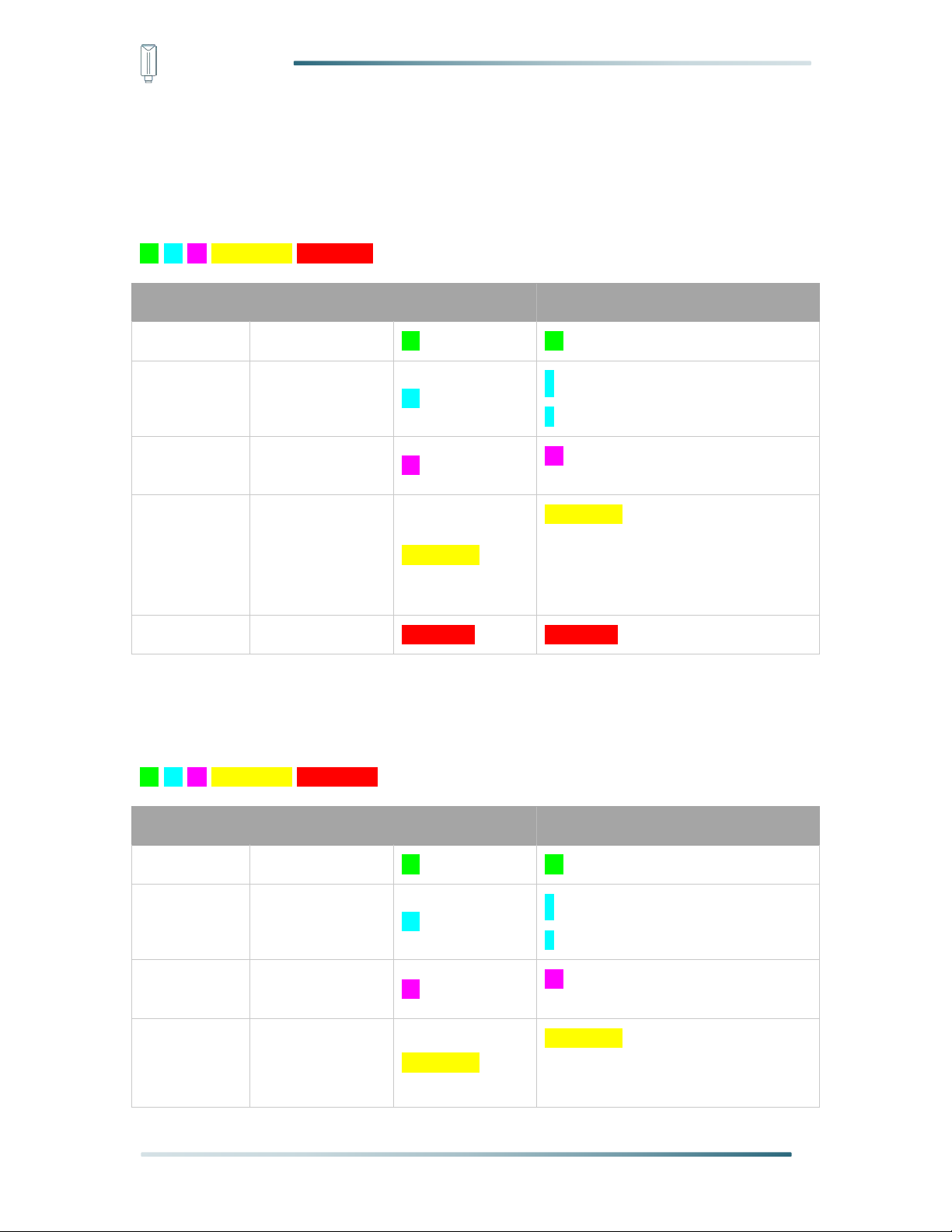
Actions
Description
Green LED Status
First power up, press and
hold for 3s
Power on and activate the
Bluetooth
Green LED flashes at 1s
frequency, waiting for
Bluetooth connection.
If Bluetooth not connected
within 1 minute, the device
would shut down again.
Press once
Reboot device and join LoRa
network
1. The green LED will be
on for 5 seconds for
initialization.
2. Waiting for join LoRa
network: red breathing
light flashing
3. Join LoRa network
success: green LED
flashes fast for 2s
4. LoRa network join
failure: red LED
suddenly stop.
Press and hold for 3s
Activate Bluetooth again
1. Waiting for Bluetooth
connection: green LED
5. LED of Sensor Working Status
The LED has green and red color, which indicates the device working status explained in the
follow table:
14
Page 16

IoT into the Wild
flashes at 1s frequency
2. Enter configuration
mode after Bluetooth
connection is
successful: green LED
flashes at 2s frequency
If Bluetooth is not
connected within 1 minute,
the device will reboot and
join LoRa network.
Press and hold for 9s
Power off
In the 3rd seconds will start
flashing at 1s frequency,
until the light is steady on,
release the button, the light
will go out.
Note:
1.After power off, you need to reconfigure the frequency band. Power off is recommended
when not deployed.
2. If the frequency is not configured after power on, the device will be power off again.
15
Page 17

IoT into the Wild
6. SenseCAP Mate App
6.1 Download App
As a tool, SenseCAP Mate App is used to configure LoRa parameters, set interval, bind
devices to your account and check device basic information.
(1) For iOS, please search for “SenseCAP Mate” in the App Store and download it.
(2) For Android, please search for “SenseCAP Mate” in the Google Store and download it.
You can also download App from https://install.appcenter.ms/orgs/seeed/apps/sensecap-
mate/distribution_groups/public
16
Page 18

IoT into the Wild
Note:
If you can't find the email, it may be automatically identified as "spam" and put in the "trash
can".
6.2 How to connect sensor to App
6.2.1 Create a New Account
SenseCAP Mate supports device configuration and remote management. To use the
SenseCAP Portal platform and other functions, please register an account.
SenseCAP Mate supports offline functionality, and you can opt out of an account if you only
use the configuration sensor. Just click Skip.
Please select Global of Server Location.
You can also create an account via the SenseCAP Portal: http://sensecap.seeed.cc
1) Select register account, enter email information and click "register", the registered email
will be sent to the user's mailbox.
2) Open the "SenseCAP…"Email, click the jump link, fill in the relevant information, and
complete the registration.
3) Return to the login interface and complete the login.
17
Page 19

IoT into the Wild
6.2.2 Connect to Sensor to App
1) Press button and hold for 3 seconds, the LED will flash at 1s frequency. Please use the
App to connect the sensor within 1 minute; otherwise, the device will power off or reboot.
2) Please select “S2100 Data Logger”.
Please click the “Setup” button to turn on Bluetooth and click “Scan” to start scanning the
sensor's Bluetooth.
3) Select the Sensor by S/N (S/N is on the front label of the sensor). Then, the basic
information of the sensor will be displayed after entering.
18
Page 20

IoT into the Wild
4) Enter configuration mode after Bluetooth connection is successful: LED flashes at 2s
frequency.
19
Page 21

IoT into the Wild
Platform
Description
SenseCAP for The
Things Network
Default platform.
It must be used with SenseCAP Outdoor Gateway
(https://www.seeedstudio.com/LoRaWAN-Gateway-EU868-p-
4305.html ). SenseCAP builds a proprietary TTN server that
enables sensors to be used out of the box when paired with an
SenseCAP outdoor gateway.
SenseCAP for Helium
When there is the Helium network around the user, data can be
uploaded using sensors. Devices run on a private Helium console
of SenseCAP. Users do not need to create devices on Helium
console, right out of the box.
Helium
Connect Sensor to public Helium console.
The Things Network
Connect Sensor to your TTN(TTS) server.
Other Platform
Other LoRaWAN Network Server.
6.3 Configure basic parameters through App
6.3.1 Select the Platform and Frequency
S210x Sensors are manufactured to support universal frequency plan from 863MHz
~928MHz in one SKU. That is to say, every single device can support 7 frequency plans.
20
Page 22

IoT into the Wild
Gateway Frequency
Description
EU868
It must be used with SenseCAP EU868 Gateway
(https://www.seeedstudio.com/LoRaWAN-Gateway-EU868-p-
4305.html )
US915
It must be used with SenseCAP US915 Gateway
(https://www.seeedstudio.com/LoRaWAN-Gateway-US915-p-
4306.html )
AU915
Need to contact sales to purchase.
1) SenseCAP for Helium:
We provide the SenseCAP Portal to manage devices and data: sensecap.seeed.cc
We built a private Helium Console with an embedded SenseCAP Portal. When users get the
SenseCAP sensors, you can use it by scanning the code and binding it to the Portal.
“SenseCAP for Helium” is selected by default. The device runs in a fixed main frequency and
sub-band, refer to Helium Frequency Plan (https://docs.helium.com/lorawan-on-
helium/frequency-plans/ ). You only need to select the main frequency, such as EU868 and
US915.
SenseCAP for Helium supports the following frequency plan:
EU868 / US915 / AU915 / KR920 / IN865 / AS923-1 / AS923-2 / AS923-3 / AS923-4
2) SenseCAP for The Things Network
SenseCAP Portal also builds the TTN private server, and the sensor must be used together
with the SenseCAP Outdoor Gateway (https://www.seeedstudio.com/LoRaWAN-Gateway-
EU868-p-4305.html).
Due to the limitation of the SenseCAP outdoor gateway frequency, “SenseCAP for TTN”
supports the following frequency plan(The sensor is capable of supporting all frequency plan):
21
Page 23

IoT into the Wild
AS923-1
Need to contact sales to purchase.
AS923-2
Need to contact sales to purchase.
3) Helium
Users can choose sensors to use on the public helium console:
https://console.helium.com/
4) The Things Network
Users can choose sensors to use on the public The Things Network server:
https://console.cloud.thethings.network/
5) Other Platform:
When you use other LoRaWAN network server, please select Other Platform.
At this point, you need to determine the sensor frequency band according to the gateway
frequency and sub-band.
S210x Sensors support the following frequency plan:
22
Page 24

IoT into the Wild
Sensor Frequency
Common
Name
Sub-band
EU863-870
EU868
--------
US902-928
US915
Sub band from 1 to 8 (default sub-band 2)
AU915-928
AU915
Sub band from 1 to 8 (default sub-band 2)
KR920-923
KR920
--------
IN865-867
IN865
--------
AS923
AS923-1
Frequency plan for Helium
AS923-2
AS923-3
AS923-4
RU864-867
RU864
--------
Note1:
Different countries and LoRaWAN network servers use different frequency plans.
For Helium network, please refer to:
https://docs.helium.com/lorawan-on-helium/frequency-plans
For The Things Network, please refer to:
https://www.thethingsnetwork.org/docs/lorawan/frequency-plans/
Note2:
1) When using the SenseCAP platform, the EUI, APP EUI and APP Key are fixed and are
the same as the sensor label.
2) When the sensor is selected to be used with a public platform such as Helium or TTN, the
EUI will not change, and the sensor will generate a new fixed App EUI and App Key for
network access.
23
Page 25

IoT into the Wild
Parameter
Type
Uplink Interval
Unit: minutes, number from 5 to 1440.
Note:
The SenseCAP portal has a limit on uplink interval: minimum interval is 5 minutes.
The interval using the other platforms ranges from 1 to 1440 minutes.
Parameter
Type
Device EUI
16 bits, hexadecimal from 0 ~ F
App EUI
16 bits, hexadecimal from 0 ~ F
App Key
32 bits, hexadecimal from 0 ~ F
6.3.2 Set the Interval
The working mode of device: wake up the device every interval and collect measurement
values and upload them through LoRa. For example, the device collects and uploads data
every 60 minutes by default.
6.3.3 Set the EUI and Key
The device uses OTAA to join the LoRaWAN network by default. So, it can set the device
EUI and App EUI.
24
Page 26

IoT into the Wild
Parameter
Description
2C+1N (default)
2C+1N (2 confirm packets and 1 none-confirm) is the best
strategy, the mode can minimize the packet loss rate, however
the device will consume the most data packet in TTN, or date
credits in Helium network.
1C
1C (1 confirm) the device will sleep after get 1 received confirm
packet from server.
1N
1N (1 none-confirm) the device only send packet and then start to
sleep, no matter the server received the data or not.
Parameter
Description
OTAA (default)
Over The Air Activation, it joins the network through Device EUI,
App EUI, and App Key.
ABP
Activation By Personalization, it joins the network through
DevAddr, NwkSkey, and AppSkey.
Parameter
Description
DevAddr
32 bits, hexadecimal from 0 ~ F
NwkSkey
32 bits, hexadecimal from 0 ~ F
AppSkey
8 bits, hexadecimal from 0 ~ F
6.3.4 Set the Packet Policy
The sensor uplink packet strategy has three modes.
6.3.5 Set the Activation Type
The sensor supports two network access modes, OTAA by default.
When using ABP mode, you need to configure the following information:
25
Page 27

IoT into the Wild
Note:
The factory defaults to a fixed key for ABP mode.
6.3.6 Restore Factory Setting
When selecting the SenseCAP platform, you must use the fixed EUI/App EUI/App Key.
Therefore, you need to restore the factory Settings before switching back to the SenseCAP
platform from other platforms.
When we make a mistake or want to reset everything, we can click the button. The device will
be restored to the factory's default configuration.
*Note: The “Restore Factory” function can only reset the Basic Setting.
26
Page 28

IoT into the Wild
Level Mode
The input level signal is collected, the high level is 1, the low level is
0
Counter Mode
The pulse signal is collected, and the number of pulses is recorded
6.4 Configure Level or Pulse Sensor via App
1) Select the “GPIO” protocol.
2) Select the supply voltage to the sensor. It supports 3V/5V/12V. Please refer to section
"Power Supply Options of Sensor".
3) Set the “Sensor Warm-up time”, the warm-up time denotes the amount of time it takes for
the sensor to attain its highest accuracy or performance level once the voltage supply has
been applied.
4) Select the input type:
27
Page 29

IoT into the Wild
6.4.1 Set the Level Mode
If your sensor is a Level output senor.Select the “Level Mode” as input type.
6.4.2 Set the Counter Mode
If your sensor is a pulse counter senor.Select the “Counter Mode” as input type. Then set the
following parameters in turn.
28
Page 30

IoT into the Wild
Sensor Warm-up Time
The warm-up time denotes the amount of time it takes for the
sensor to attain its highest accuracy or performance level once the
voltage supply has been applied.
Digital input
Sets the type of input pulse.
Pull High: Valid when a rising edge is detected.
Pull Low: Valid when a falling edge is detected.
Digital Filter
When the pulse width exceeds 10 ms, which advised to enable it. It
is enabled by default.
Reboot to clear the
count
When a Datalogger restart occurs, the count is cleared to 0. It is
disabled by default.
Y= Ax + B
“Y”: It is the value Datalogger will upload.
“x”: It is the original counter value.
Factory A: Custom values that can be scaled up or down by
multiples of the “x”.
Factory B: A custom value that increments or diminishes the value
of the “x”.
By setting the values of A and B, you can calculate the desired
value. If only raw counter values are uploaded, set A=1 and B=0.
Unit time collection
Enabling this function increases upload by a value: cumulative
amount per hour.
29
Page 31

IoT into the Wild
For example, if the value of Y within one hour is 1000, 1000/h will
be uploaded.
30
Page 32

IoT into the Wild
Power Type
Periodic power: Power the sensor before data collection, and power
off the sensor after data collection. This mode reduces power
consumption and increases battery life.
Always-on: Select this mode when the sensor needs constant
power supply. Generally, an external 12V DC power supply is used.
If it is powered only by batteries, it may not work for long.
Power Voltage
Select the supply voltage to the sensor. It supports 3V/5V/12V.
Please refer to section "Power Supply Options of Sensor".
Analog Input
Current: Select the current signal of the sensor from 4 to 20mA.
Voltage: Select the voltage signal of 0~10V sensor.
Sensor Warm-up Time
The warm-up time denotes the amount of time it takes for the
sensor to attain its highest accuracy or performance level once the
voltage supply has been applied.
Current Range
4~20mA
6.5 Configure Analog Sensor via App
Select the “Protocol” as “Analog input”. Then set the following parameters in turn.
6.5.1 Set the 4~20mA sensor
31
Page 33

IoT into the Wild
Interface I1
The Data Logger supports two analog current signals. When the
sensor wire is connected to I1/I2, the configuration can be enabled.
Interface I2
Y= Ax + B
“Y”: It is the value Datalogger will upload.
“x”: It is the original current value.
Factory A: Custom values that can be scaled up or down by
multiples of the “x”.
Factory B: A custom value that increments or diminishes the value
of the “x”.
By setting the values of A and B, you can calculate the desired
value. If only raw values are uploaded, set A=1 and B=0.
Sensor Warm-up Time
The warm-up time denotes the amount of time it takes for the
sensor to attain its highest accuracy or performance level once the
voltage supply has been applied.
Current Range
0~10V (The Data Logger can collect voltage signals within 0~10V
and automatically adjust the upper limit to increase accuracy)
6.5.1 Set the 0~10V Voltage sensor
32
Page 34

IoT into the Wild
Interface V1
The Data Logger supports two analog voltage signals. When the
sensor wire is connected to V1/V2, the configuration can be
enabled.
Interface V2
Y= Ax + B
“Y”: It is the value Data Logger will upload.
“x”: It is the original current value.
Factory A: Custom values that can be scaled up or down by
multiples of the “x”.
Factory B: A custom value that increments or diminishes the value
of the “x”.
By setting the values of A and B, you can calculate the desired
value. If only raw values are uploaded, set A=1 and B=0.
33
Page 35

IoT into the Wild
Baud Rate
Baud rate of communication with the sensor.
Range: 4800/9600/14400/19200/38400/57600/115200
Modbus Address
Slave address of the sensor. The range is 1 to 247.
Power Type
Periodic power: Power the sensor before data collection, and power
off the sensor after data collection. This mode reduces power
consumption and increases battery life.
Always-on: Select this mode when the sensor needs constant
power supply. Generally, an external 12V DC power supply is used.
If it is powered only by batteries, it may not work for long.
Power Voltage
Select the supply voltage to the sensor. It supports 3V/5V/12V.
Please refer to section "Power Supply Options of Sensor".
Sensor Warm-up Time
The warm-up time denotes the amount of time it takes for the
sensor to attain its highest accuracy or performance level once the
voltage supply has been applied.
Response Timeout
After Data Logger initiates a data read request to the sensor, it
waits for the timeout time for a response. If this time is exceeded,
the command will be resent; unit: 100 milliseconds.
6.6 Configure RS485 Modbus-RTU Sensor via App
Select the “Protocol” as “RS485 Modbus RTU”. Then set the following parameters in turn.
34
Page 36

IoT into the Wild
Startup Time
The length of time the sensor can communicate from powered -on
to communicating with Modbus, unit: 100 milliseconds.
Measurement Number
Data Logger can collect 0 to 10 measurements in RS485 mode.
Measurement Setting
Set the register of the measurement value and other configurations.
Register Address
The register address of the measured value in the sensor, which is
an integer.
Function Code
Modbus function code, supports 01/02/03/04 function code.
Data Type
The data type determines the number of registers read from the
sensor and how the data should parse the value.
There are some options:
Unsigned 16bit integer,0xAB
Signed 16bit integer, 0xAB
Unsigned 32bit integer, 0xABCD
Unsigned 32bit integer, 0xCDAB
……
Precision
Precision of the value. You can choose the decimal place of the
measurement value. If 1 is selected, one decimal place is reserved.
0, #
1, #.#
2, #.##
…
Y= Ax + B
“Y”: It is the value of Data Logger will upload.
“x”: It is the original current value.
Factory A: Custom values that can be scaled up or down by
multiples of the “x”.
Factory B: A custom value that increments or diminishes the value
of the “x”.
By setting the values of A and B, you can calculate the desired
value. If only raw values are uploaded, set A=1 and B=0.
Measurement Setting
Set each measurement in turn
35
Page 37

IoT into the Wild
Write Strategy
This function is enabled only for some special sensors and is
generally disabled by default
After reading the value of the register, special instructions can be
issued to the sensor, such as the instruction to empty the register
after reading register 0.
None: Off by default.
After Read: Send the RS485 command to sensor after reading the
register.
On New Data: Send the RS485 command to sensor every 24
hours.
36
Page 38

IoT into the Wild
Note:
If you can't find the email, it may be automatically identified as "spam" and put in the "trash
can".
7. Connect to the SenseCAP Portal
7.1 SenseCAP Portal
The main function of the SenseCAP Portal is to manage SenseCAP devices and to store
data. It is built on Azure, a secure and reliable cloud service from Microsoft. You can apply for
an account and bind all devices to this account. SenseCAP provides the web portal and API.
The web portal includes Dashboard, Device Management, Data Management, and Access
Key Management, while API is open to users for further development.
7.1.1 Create a New Account
Portal Website: http://sensecap.seeed.cc
4) Select register account, enter email information and click "register", the registered email
will be sent to the user's mailbox.
5) Open the "SenseCAP…"Email, click the jump link, fill in the relevant information, and
complete the registration.
6) Return to the login interface and complete the login.
7.1.2 Other Functions
Dashboard: Including Device Overview, Announcement, Scene Data, and Data Chart,
etc.
37
Page 39

IoT into the Wild
Note:
SenseCAP Portal User Guide: https://sensecap-docs.seeed.cc/quickstart.html
Device Management: Manage SenseCAP devices.
Data Management: Manage data, including Data Table and Graph section, providing
methods to search for data.
Subaccount System: Register subaccounts with different permissions.
Access Key Management: Manage Access Key (to access API service), including Key
Create, Key Update, and Key Check.
7.1.3 API Instruction
SenseCAP API is for users to manage IoT devices and data. It includes 3 types of API
methods: HTTP protocol, MQTT protocol, and Websocket protocol.
With HTTP API, users can manage LoRa devices, to get raw data or historical data.
With MQTT API, users can subscribe to the sensor's real-time measurement data
through the MQTT protocol.
With Websocket API, users can get real-time measurement data of sensors through
Websocket protocol.
Please refer to this link for API User Guide: https://sensecap-docs.seeed.cc/
38
Page 40

IoT into the Wild
7.2 Connect to SenseCAP with Helium Network
7.2.1 Quick Start
Follow this process to quickly use the sensor, see the following section for details.
7.2.2 Preparation
1) SenseCAP Mate App
Download the App, please refer to section 5 for using.
2) Coverage of Helium network
Option 1: Use the Helium network that already exists nearby.
Please refer to the map, search your location to see if there's any helium network around:
https://explorer.helium.com/
39
Page 41

IoT into the Wild
A green hexagon indicates the presence of the network.
Option 2: Deploy a new Helium gateway.
You can purchase M1, M2 gateways to cover your surroundings with the Helium network:
https://www.sensecapmx.com/
7.2.3 Bind Sensor to SenseCAP Portal
Please open SenseCAP Mate App.
(1) Scan QR Code
1) Click “Add device” on the upper-right corner of device page to enter the device binding
page.
2) Scan the QR code on the device to bind the device to your account. If you do not set it to
a designated group, the device will be put into the “default” group.
40
Page 42

IoT into the Wild
(2) Manually fill in the EUI
If the QR code sticker is damaged, you can manually fill in the EUI of the device to bind the
device to your account. Please make sure you put in the EUI in the format suggested by the
system and then click “confirm”.
41
Page 43

IoT into the Wild
7.2.4 Setup the Sensor
1) Open the SenseCAP Mate App
2) Press button and hold for 3 seconds, the LED will flash at 1s frequency.
3) Please click the “Setup” button to turn on Bluetooth and click“Scan”to start scanning the
sensor's Bluetooth.
4) Select the Sensor by S/N (label). Then, the basic information of the sensor will be
displayed after entering.
42
Page 44

IoT into the Wild
7.2.5 Set Frequency of Sensor via SenseCAP Mate App
Set the corresponding frequency band based on the frequency band of the gateway.
Please refer to section 5 for detail.
1) Click the “Setting” and select the platform is “SenseCAP for Helium”.
43
Page 45

IoT into the Wild
2) Select the Frequency Plan, if the gateway is US915, set the sensor to US915.
3) Click the “Send” button, send the setting to the sensor for it to take effect.
4) Click the “Home” button, the App will disconnect the Bluetooth connection.
Then, the sensor will reboot.
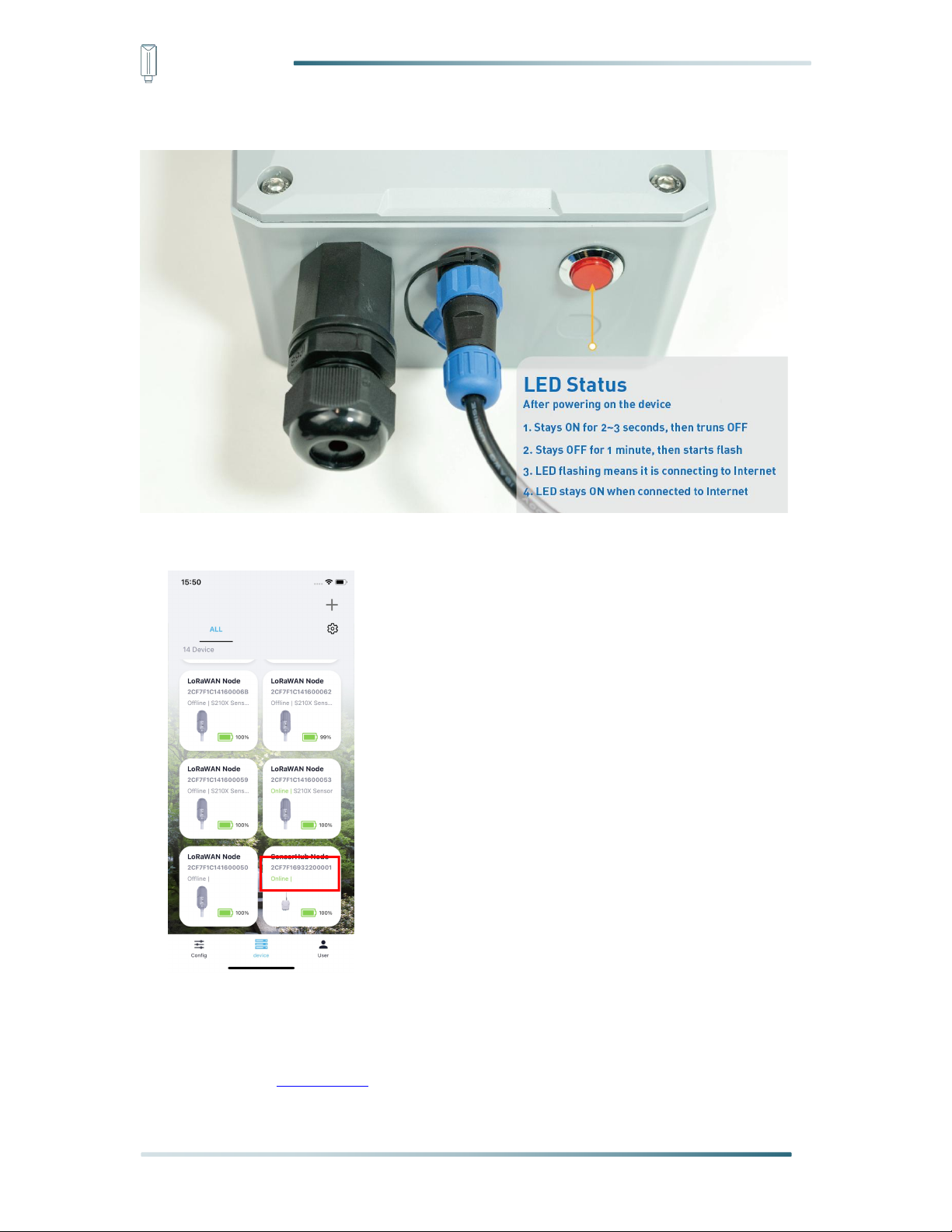
5) When the device is disconnected from Bluetooth, the LED lights up for 5 seconds and
then flashes as a breathing light.
6) After joining the network successfully, LED flashes fast for 2s.
7.2.6 Check Data on SenseCAP Portal
On the SenseCAP App or the website http://sensecap.seeed.cc/ , you can check the device
online status and the latest data. In the list for each Sensor, you can check its online status
and the time of its last data upload.
44
Page 46

IoT into the Wild
45
Page 47

IoT into the Wild
7.3 Connect to SenseCAP with private TTN
7.3.1 Quick Start
Follow this process to quickly use the sensor, see the following section for details.
7.3.2 Preparation
1) SenseCAP Mate App
Download the App, please refer to section 5 for using.
2) SenseCAP Outdoor Gateway
Now, the sensor needs to be used with the SenseCAP Outdoor Gateway
(https://www.seeedstudio.com/LoRaWAN-Gateway-EU868-p-4305.html) to transmit data to
the SenseCAP Portal.
a) Setup the Gateway, connect to power cable and Internet.
b) Bind the gateway to SenseCAP Portal.
46
Page 48
IoT into the Wild
c) Ensure the gateway indicator is steady on.
d) Ensure the gateway is displayed online on the portal.
7.3.3 Bind Sensor to SenseCAP Portal
Please refer to the section 6.2.3
47
Page 49

IoT into the Wild
7.3.4 Setup the Sensor
Please refer to the section 6.2.4
7.3.5 Set Frequency of Sensor via SenseCAP Mate App
Set the corresponding frequency band based on the frequency band of the gateway.
Please refer to section 5 for detail.
1) Click the “Setting” and select the platform is “SenseCAP for The Things Network”.
2) Select the Frequency Plan, if the gateway is US915, set the sensor to US915.
3) Click the “Send” button, send the setting to the sensor for it to take effect.
4) Click the “Back to Home” button, the App will disconnect the Bluetooth connection.
Then the sensor will reboot.
5) When the device is disconnected from Bluetooth, the LED lights up for 5 seconds and
then flashes as a breathing light.
48
Page 50

IoT into the Wild
6) After joining the network successfully, LED flashes fast for 2s.
7.3.6 Check Data on SenseCAP Portal
Please refer to the section 6.2.6
49
Page 51

IoT into the Wild
8. Connect to Helium Network
Please refer to the manual to connect sensors to Helium public console:
https://files.seeedstudio.com/products/SenseCAP/S210X/How%20to%20Connect%20Sense
CAP%20S210X%20to%20Helium%20Network.pdf
9. Connect to The Things Network
Please refer to this manual:
https://files.seeedstudio.com/products/SenseCAP/S210X/How%20to%20Connect%20Sense
CAP%20S210X%20to%20The%20Things%20Network.pdf
Please refer to the link to use the TTN platform:
The Things Network website: https://www.thethingsnetwork.org
The Things Industries login: https://accounts.thethingsindustries.com/login
TTN Quick Start: https://www.thethingsnetwork.org/docs/quick-start/
50
Page 52

IoT into the Wild
10. Payload Decoder
10.1 Decoder Code
TTN payload decoding script for SenseCAP LoRaWAN:
https://github.com/Seeed-Solution/TTN-PayloadDecoder/blob/master/SenseCAP_LoRaWAN_V2_Decoder.js
51
Page 53

IoT into the Wild
31
Byte2
Byte3
Byte4
Byte5
Byte6
Byte7
Byte8
Byte9
Byte10
Byte11
ID
Meas
urem
ent m
and n
Flag bit
The value of Measurement m
The value of Measurement n
30
Byte2
Byte3
Byte4
Byte5
Byte6
Byte7
Byte8
Byte9
Byte10
Byte11
ID
Meas
urem
ent m
and n
Flag bit
and total
packet
number
The value of Measurement m
The value of Measurement n
10.2 Packet Parsing
10.2.1 Packet Initialization
After being powered on or reboot, SenseCAP Sensors will be connected to the network using
the OTAA activation method. Each Sensor Node will send data packets to the server,
including the following data:
The data logger protocol provides 3 types of packets to correspond to different information
such as measurements, and the number of bytes of each packet may vary. The structure of
the frame is shown in the below. The frame content is sent in big-endian byte order.
0x31: Measurements ≤2, send the packet ID at 0x31.
Byte2: The measurement ID ranges from 1 to 10. It corresponds to the measurement number.
Byte 3: The bit1 indicates the reserved flag bit, bit2 to bit8 are fixed to 1.
0x30/0x32/0x33: When the number of measurements
packets: first(0x30), middle(0x32), and final(0x33). Each package includes 2
measurements.
Byte2: The measurement ID ranges from 1 to 10. It corresponds to the measurement number.
Byte 3: The bit1 indicates the reserved flag bit. The bit2 to the bit5 indicates the total number
of uploaded packets, bit6 to bit8 are fixed to 1.
2, there are three types of
>
52
Page 54

IoT into the Wild
32
Byte2
Byte3
Byte4
Byte5
Byte6
Byte7
Byte8
Byte9
Byte10
ID
Meas
urem
ent m
and n
The value of Measurement m
The value of Measurement n
33
Byte2
Byte3
Byte4
Byte5
Byte6
Byte7
Byte8
Byte9
Byte10
Byte11
ID
Meas
urem
ent m
and n
Flag bit
and total
packet
number
The value of Measurement m
The value of Measurement n
39
Byte2
Byte3
Byte4
Byte5
Byte6
Byte7
Byte8
Byte9
Byte10
ID
Battery
Level
Software & Hardware Version
Measurement
Uplink Interval
Reserved
Byte 3: The bit1 indicates the reserved flag bit. The bit2 to the bit5 indicates the total number
of uploaded packets, bit6 to bit8 are fixed to 1.
0x39: Battery package
53
Page 55
IoT into the Wild
Part
Value
Raw Data
Description
31
ID
31
31 is the package ID.
Byte2
Measurement 1
10
1: Measurement 1
0: No measurements.
Byte3
Flag bit
01
01: The reserved flag bit can be
ignored.
Byte4~Byte7
The value of
Measurement 1
000067DE
000067DE is 0x000067DE, whose
equivalent decimal value is 26590.
Divide it by 1000, and you will get
the actual measurement value for air
temperature as 26.59 ℃.
Byte 8~Byte11
None
80000000
80000000 mean no measurements.
Part
Value
Raw Data
Description
31
ID
31
31 is the package ID.
Byte2
Measurement
12
1:Measurement 1
2: Measurement 2
Byte3
Flag bit
02
01: The reserved flag bit can be
ignored.
Byte4~Byte7
The value of
Measurement 1
000067DE
000067DE is 0x000067DE, whose
equivalent decimal value is 26590.
Divide it by 1000, and you will get
the actual measurement value for air
10.3 Data Parsing Example
10.3.1 Example - one measurement
Air Temperature and Humidity Sensor measurement packet:
31 10 01 000067DE 80000000
10.3.2 Example - two measurements
Air Temperature and Humidity Sensor measurement packet:
31 12 02 000067DE 0000C26A
54
Page 56

IoT into the Wild
temperature as 26.59 ℃.
Byte 8~Byte11
The value of
Measurement 2
0000C26A
0000C26A is 0x0000C26A, whose
equivalent decimal value is 49770.
Divide it by 1000, and you will get
the actual value for air humidity as
49.77%RH.
Part
Value
Raw Data
Description
30
ID
30
31 is the package ID.
Byte2
Measurement
12
1:Measurement 1
2: Measurement 2
Byte3
Flag bit
02
02: The reserved flag bit can be
ignored.
Byte4~Byte7
The value of
Measurement 1
000067DE
000067DE is 0x000067DE, whose
equivalent decimal value is 26590.
Divide it by 1000, and you will get
the actual measurement value for air
temperature as 26.59 ℃.
Byte 8~Byte11
The value of
Measurement
2
0000C26A
0000C26A is 0x0000C26A, whose
equivalent decimal value is 49770.
Divide it by 1000, and you will get
the actual value for air humidity as
49.77%RH.
33
ID
33
33 is the package ID.
Byte13
Measurement
34
3:Measurement 3
4: Measurement 4
Byte14
Flag bit
02
02: The reserved flag bit can be
ignored.
Byte15~Byte18
The value of
Measurement 3
05F98A88
05F98A88 is 05F98A88, whose
equivalent decimal value is
100240008. Divide it by 1000, and
you will get the actual measurement
10.3.3 Example - four measurements
Air Temperature, Humidity, Barometric pressure and Light intensity Sensor measurement
packet:
30 12 02 000067DE 0000C2A6 33 34 02 05F98A88 00019A28
55
Page 57

IoT into the Wild
value for Barometric pressure
100240.008 Pa.
Byte 19~Byte22
The value of
Measurement
4
00019A28
00019A28 is 0x00019A28, whose
equivalent decimal value is 105000.
Divide it by 1000, and you will get
the actual value for Light intensity as
105Lux.
Part
Value
Raw Data
Description
30ID30
31 is the package ID.
Byte2
Measurement
12
1: Measurement 1
2: Measurement 2
Byte3
Flag bit
03
03: The reserved flag bit can be
ignored.
Byte4~Byte7
The value of
Measurement
1
000067DE
000067DE is 0x000067DE, whose
equivalent decimal value is 26590.
Divide it by 1000, and you will get
the actual measurement value for air
temperature as 26.59 ℃.
Byte 8~Byte11
The value of
Measurement
2
0000BBB2
0000BBB2 is 0x0000BBB2, whose
equivalent decimal value is 48050.
Divide it by 1000, and you will get
the actual value for air humidity as
48.05%RH.
32ID32
32 is the package ID.
Byte13
Measurement
34
3: Measurement 3
4: Measurement 4
Byte14~Byte17
The value of
Measurement
3
05F62F28
05F62F28 is 0x05F62F28, whose
equivalent decimal value is
100020008. Divide it by 1000, and
you will get the actual measurement
value for Barometric pressure
100020.008 Pa.
10.3.4 Example - six measurements
Air Temperature, Humidity, Barometric pressure, Light intensity, Average wind direction, and
Average wind direction Sensor measurement packet:
30 12 03 000067DE 0000BBB2 32 34 05F62F28 00036EE8 33 56 03 0000FFDC 00000514
56
Page 58

IoT into the Wild
Byte 18~Byte21
The value of
Measurement
4
00036EE8
00036EE8 is 0x00036EE8, whose
equivalent decimal value is 225000.
Divide it by 1000, and you will get
the actual value for Light intensity as
225 Lux.
33ID33
33 is the package ID.
Byte23
Measurement
56
5: Measurement 5
6: Measurement 6
Byte24~Byte27
Flag bit
03
03: The reserved flag bit can be
ignored.
Byte25~Byte28
The value of
Measurement
5
0000FFDC
0000FFDC is 0x0000FFDC, whose
equivalent decimal value is 65500.
Divide it by 1000, and you will get
the actual measurement value for
Average wind direction as 65.5°.
Byte29~Byte32
The value of
Measurement
6
00000514
00000514 is 0x00000514, whose
equivalent decimal value is 1300.
Divide it by 1000, and you will get
the actual value for Average wind
speed as 1.3 m/s.
10.3.5 Battery Information
57
Page 59

IoT into the Wild
Part
Value
Raw Data
Description
39ID39
39 is the package ID.
Byte2
Battery
Level
64
64 is actually 0x64, whose equivalent decimal
value is 100. the actual battery value for
device is 100%.
Byte3~Byte6
Software &
Hardware
Version
01010002
0x01010002 -> 1.1-0.2
Software Version 1.1
Hardware Version 0.2
Byte7~Byte8
Measurement
Uplink Interval
0005
0005 is actually 0x0005,whose equivalent
decimal value is 5. The actual uplink interval
is 5 minutes.
Byte9~Byte10
Reserved
0000
Reserved Value 0000
Original Info:
39 64 01010002 00050000 3402000100
3402000100 is a status package which can be ignored.
Battery Package: 39 64 01010002 00050000
58
Page 60

IoT into the Wild
0x00
0x89
0x00
prepareId_L
prepareId_H
duty_L
duty_H
crc-L
crc-H
0x00
Fixed field
0x89
Fixed field
0x00
Fixed field
prepareId_L
Command ID low byte, you can customize the values, it allows each command ID
to be the same
prepareId_H
Command ID high byte, you can customize the values, it allows each command ID
to be the same
duty_L
Data interval low byte, you can set the data interval, unit: minute
duty_H
Data interval high byte, you can set the data interval, unit: minute
crc-L
CRC low byte, it’s calculated by the CRC-16/CCITT
crc-H
CRC low byte, it’s calculated by the CRC-16/CCITT
0x00
0x1F
0x00
prepareId_L
prepareId_H
result
0x00
crc-L
crc-H
0x00
Fixed field
0x1F
Fixed field
0x00
Fixed field
prepareId_L
Command ID low byte, it is the same as the downlink command
prepareId_H
Command ID high byte, it is the same as the downlink command
result
If the downlink command is in force, it responds 0x01, else it responds 0x00
0x00
Fixed field
crc-L
CRC low byte, it’s calculated by the CRC-16/KERMIT
crc-H
CRC low byte, it’s calculated by the CRC-16/ KERMIT
11. LoRaWAN Downlink Command
11.1 Set the Data Uplink Interval
(1) Using the Network Server’s portal or API to send downlink command, then the Node will
respond to the ack. The downlink command takes effect and responds the next time the
node uploads data.
(2) Downlink as follow:
(3) When you send the downlink command, the Node responds to the ack command.
(3) Use the FPort = 2
CRC Tool: https://crccalc.com/ , select the algorithm of CRC-16/KERMIT.
Example: Set the Node’s data interval is 10 minutes.
Send the downlink command (HEX) via FPort=2:
00 89 00 11 22 0A 00 38 B4
59
Page 61

IoT into the Wild
0x00
0x89
0x00
prepareId_L
prepareId_H
duty_L
duty_H
crc-L
crc-H
00890011220A0038B4
0x00
0x1F
0x00
prepareId_L
prepareId_H
result
0x00
crc-L
crc-H
001F001122
010078
0F
Description
Command
Set Uplink interval = 1 minute
008900112201009050
Set Uplink interval = 5 minutes
00890011220500F037
Set Uplink interval = 10 minutes
00890011220A0038B4
Set Uplink interval = 15 minutes
00890011220F0080CA
Set Uplink interval = 20 minutes
0089001122150061V2
Set Uplink interval = 30 minutes
00890011221E00C946
Set Uplink interval = 60 minutes
00890011223C004A56
ACK Response:
00 1F 00 11 22 01 00 78 0F
Command List:
11.2 Reboot the device
FPort = 2
Command: 00C800000000002B26
11.3 How to send downlink
Example: use the Helium Console to send
60
Page 62

IoT into the Wild
61
Page 63

IoT into the Wild
12. Device Installation
12.1 Check the waterproof performance of the device
12.1.1 Data logger connection port
1) Check the connection position of the probe of the Datalogger to ensure that the screw
cap is tightened.
2) The waterproof tape can be used to wrap the connection around many circles to
strengthen the waterproof performance.
12.1.2 Waterproof check
When assembling the device, it is necessary to install the waterproof pad of the Data Logger
and the adapter box, and tighten the screw cap and screw, otherwise the waterproof effect of
the device may be affected!
If the wire diameter is too small, it can be wrapped with waterproof tape, as shown below:
12.2 Installing Sensor
12.2.1 Installing the Sensor Bracket
Specially designed for installing SenseCAP Sensors, the bracket is a sliding cap. With
designated screw-holes, the bracket helps fasten the Sensor Node firmly onto a pole or a wall.
62
Page 64

IoT into the Wild
1) With the sensor in one hand and a bracket in the other, find an unobstructed direction
along the back of the sensor.
2) One hand holds the clasp while the other holds the device. Pull outward with opposite
force. Press the upper part of the buckle with your finger.
63
Page 65

IoT into the Wild
12.2.1 Mount on Pole and Wall
1) Mount on pole
2) Mount on wall
64
Page 66

IoT into the Wild
65
Page 67

IoT into the Wild
Battery Specification
Nominal capacity
19000mAh
Model
Li-SOCl2, ER34615
Nominal voltage
3.6V
Max. continuous current
230mA
Max. pulse current capability
400mA
Dimension
∅
34.0*61.5mm (D size)
Operating temperature range
-60℃ to 85℃
12.3 Replace the Battery
12.3.1 How to Buy the Battery
We suggest buying it from Amazon.
1) EEMB ER34615: Click here
2) Search the key word: LiSOCI2 ER34615 battery. Compare the batteries that meet the
following parameters. The most important thing is to match the voltage.
66
Page 68

IoT into the Wild
Note:
The sensor and PCBA are connected by wire, please disassemble carefully.
Note:
Pay attention to the positive and negative terminals of the battery.
12.3.2 How to Replace a New Battery
1) Remove three screws.
2) Install a new battery.
67
Page 69

IoT into the Wild
Note:
During the installation, ensure that the waterproof washer is properly installed and the screws
are locked; otherwise, water will flow into the device.
3) Install screws.
68
Page 70

IoT into the Wild
Version
Date
Description
Editor
V1.0.0
9/05/2022
First edition
Jenkin Lu
V1.1.0
9/23/2022
Second edition
Kelvin Lee
V1.1.1
9/30/2022
Modifying data Parsing
Kelvin Lee
V1.1.2
9/30/2022
Modifying battery information
Kelvin Lee
V1.1.3
12/1/2022
Delete “Work Mode”
Kelvin Lee
13. Trouble Shooting
13.1 Sensors can’t join LoRa network, how to do?
1) Check the gateway frequency configuration. Make sure the gateway and Sensor Node
have the same uplink and downlink frequency.
2) Check the real-time log and RESET the sensor to see if there are any sensor data
packets. If there are packets, check whether the gateway is sending downlink packets.
3) If the channels and other configurations are correct and the gateway logs do not have
packets, please contact technical support.
13.2 Why is the new sensor’s battery not 100%?
Battery power detection is not high precision. Its principle is to measure the supply voltage,
when the power is turned on and repeatedly RESET, the voltage is unstable, so it is not
100%. When the sensor is stable, the power will be more accurate.
13.3 Support
Support is provided Monday to Friday, from 09:00 to 18:00 GMT+8. Due to different time
zones, we cannot offer live support. However, your questions will be answered as soon as
possible in the before-mentioned schedule.
Provide as much information as possible regarding your enquiry (product models, accurately
describe your problem and steps to replicate it etc.) and send a mail to: sensecap@seeed.cc
13.4 Document Version
69
 Loading...