

User manual/ Technical information
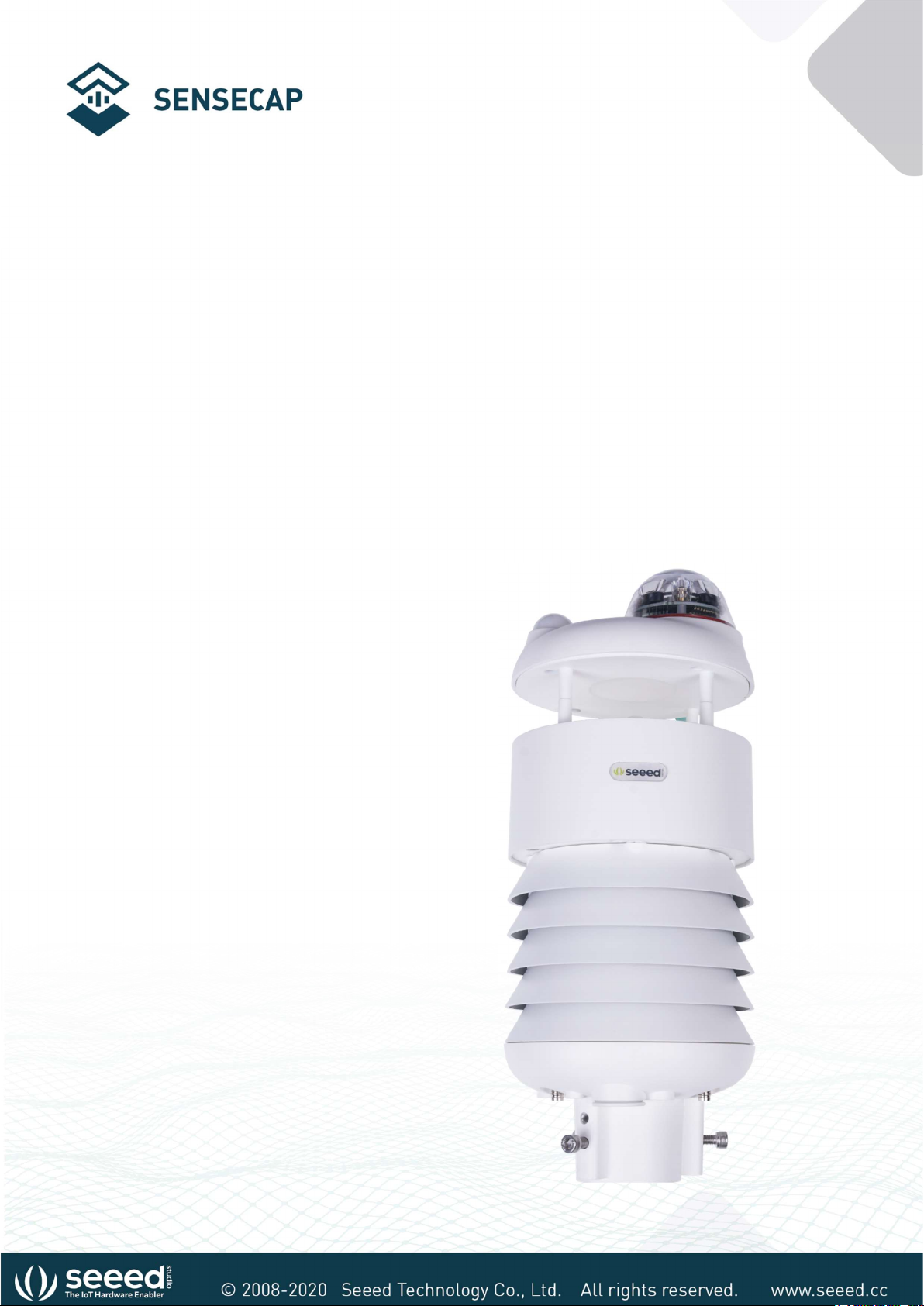
User Manual for All-in-One
Weather Sensors
SenseCAP ONE Series
Version: V1. 4
Dates: 2020-4-16
© 2008-2020 Seeed Technology Co., Ltd. All rights reserved. www.seeed.cc
The 1 Page total 50 Page

User manual/ Technical information
Tables of Contents
Tables of Contents .................................................................................................................................................. 2
1 Product Introduction ..................................................................................................................................... 5
2 Installation ........................................................................................................................................................ 7
Packing List ........................................................................................................................................... 8
Installation ............................................................................................................................................ 9
2.2.1 Device Interface Introduction .............................................................................................. 9
2.2.2 Connect with USB Cable ..................................................................................................... 10
2.2.3 M12 Cable ............................................................................................................................... 10
2.2.4 Install the device. .................................................................................................................. 12
3 Device's Operating Mode ........................................................................................................................... 17
Configure the device via USB port ............................................................................................... 18
SenseCAP ONE Configuration Tool .............................................................................................. 19
Serial debug tool............................................................................................................................... 24
4 Communication Protocols .......................................................................................................................... 26
Modbus-RTU Protocol ..................................................................................................................... 27
4.1.1 Modbus-RTU Protocol Message Format ........................................................................ 27
4.1.2 Register Address Definition ............................................................................................... 28
4.1.3 Modbus-RTU Read ............................................................................................................... 29
ASCII Protocol .................................................................................................................................... 33
4.2.1 Command definition ............................................................................................................ 33
© 2008-2020 Seeed Technology Co., Ltd. All rights reserved. www.seeed.cc
The 2 Page total 50 Page

User manual/ Technical information
4.2.2 Query Command Format .................................................................................................... 34
4.2.3 Setting Command Format .................................................................................................. 34
4.2.4 Command List ........................................................................................................................ 34
SDI-12 .................................................................................................................................................. 42
4.3.1 SDI-12 command and response ....................................................................................... 42
4.3.2 SDI-12 Read ............................................................................................................................ 45
6 Error code ............................................................................................................................................................ 50
Modbus error code ................................................................................................................................ 50
ASCII error code...................................................................................................................................... 50
SDI-12 error code ................................................................................................................................... 50
© 2008-2020 Seeed Technology Co., Ltd. All rights reserved. www.seeed.cc
The 3 Page total 50 Page

User manual/ Technical information
Version Description Date The modifier
V1.0 Initial version 02-09-2020 Kevin Yang
V1.1
V1.2
V1.3 Add heating function, PM2.5/10, SDI-12 protocol, etc. 12-4-2021 Kevin Yang
Modify the Modbus protocol section, barometric
pressure value calculation method
Modify the definition for these 2 symbols “&”, “;” in
the return values of ASIIC protocol.
Modify the command for rain-related parameters in the
ASIIC protocol; add Clear command
09-12-2020 Kevin Yang
24-12-2020 Kevin Yang
© 2008-2020 Seeed Technology Co., Ltd. All rights reserved. www.seeed.cc
The 4 Page total 50 Page

User manual/ Technical information
1 Product Introduction
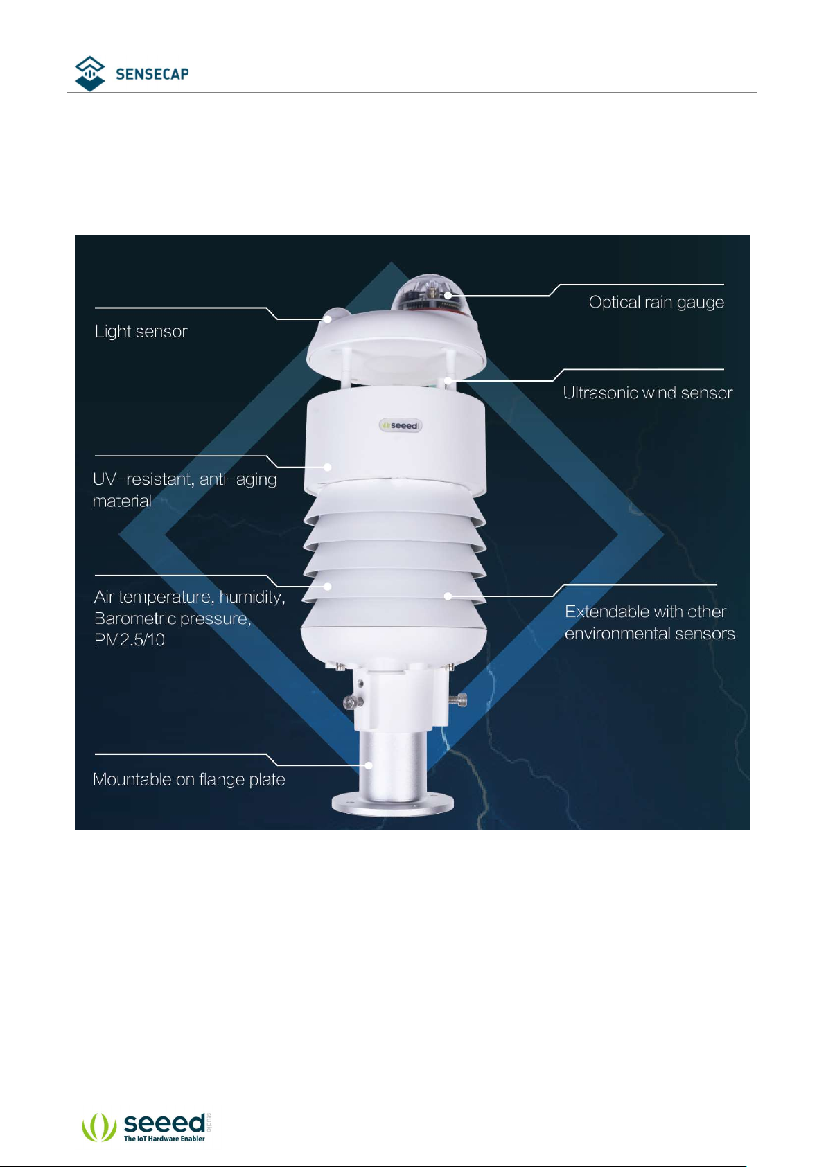
SenseCAP ONE is a series of all-in-one compact weather sensors, including S900 9-in-1, S700 7-
in-1, and S500 5-in-1 weather sensors. These weather sensors integrate multiple sensors into this
compact device, monitoring up to 9 weather parameters: air temperature, air humidity,
atmospheric pressure, light intensity, wind speed, wind direction, precipitation, PM 2.5, and PM
10. The sensors use ultrasonic to measure wind speed and wind direction, to achieve high-
precision data collection, which is easy maintenance. The equipment is designed with industry
standards and can work stably in harsh outdoor environments from -40°C to 85°C. The product
supports the Modbus-RTU (RS232/RS485/RS422), ASCII, and SDI-12 protocol.
Basic parameters
Product Model SenseCAP ONE S700
Power Supply 12V ~ 24V(1W)
Heating Power Supply 12V ~ 24V(2W)
Support Protocols Modbus-RTU (RS232/RS485/RS422) , ASCII and SDI-12 protocol
IP Rating IP65
Working Temperature -40 ℃ ~ + 85℃
Working Humidity 0 to 100%RH (non-condensing).
Measurement Parameters
Measurements Range Accuracy Resolution
Air Temperature -40~85°C ±0.1℃ 0.01°C
Air Humidity 0~ 100%RH ±1.5%RH 0.01%RH
Barometric Pressure 300~1250hPa ±50Pa 10 Pa
Light Intensity 0~188000 Lux ±5%*MV(measurement value) 5Lux
Wind Speed 0~60 m/s(@-40℃~60℃)
Wind Direction 0~360°(@-40℃~60℃) ±3.0° 0.1°
© 2008-2020 Seeed Technology Co., Ltd. All rights reserved. www.seeed.cc
The 5 Page total 50 Page
±0.3m/s,(≤10m/s)
± 3%* MV(≥10m/s)
0.1m/s

User manual/ Technical information
Precipitation 0~200mm/h ±5% 0.2mm/0. 02mm
PM2.5 0~1000µg/𝑚3
PM10 0~1000µg/𝑚3
±10%@100~1000µg/𝑚3
±10µg/𝑚3@0~100µg/𝑚3
±15%@100~1000µg/𝑚3
±15µg/𝑚3@0~100µg/𝑚3
1µg/𝑚3
1µg/𝑚3
The 6 Page total 50 Page
© 2008-2020 Seeed Technology Co., Ltd. All rights reserved. www.seeed.cc
User manual/ Technical information
2 Installation
Before the installation, check the packing list and make sure there are no missing parts.
© 2008-2020 Seeed Technology Co., Ltd. All rights reserved. www.seeed.cc
The 7 Page total 50 Page

User manual/ Technical information
Packing List
Number Parts Number
1 SenseCAP ONE All-in-one compact weather sensor 1
M12 8-pin communication cable (default length 3-meter hook-up wire,
2
and there is a waterproof aviation connector type to choose when
1
working with SenseCAP SensorHub datalogger)
3 USB Type-C cable, for configuring devices 1
4 Flange plate (purchased separately) 1
5 Pole adapter sleeve base (purchased separately) 1
6 Pole adapter cross bar (purchased separately) 1
© 2008-2020 Seeed Technology Co., Ltd. All rights reserved. www.seeed.cc
The 8 Page total 50 Page
User manual/ Technical information
Installation
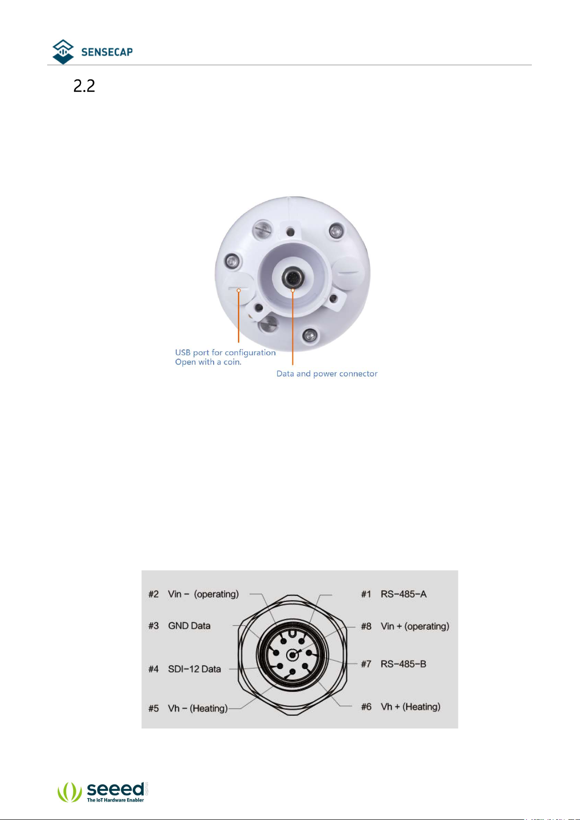
2.2.1 Device Interface Introduction
There are two connectors at the bottom of the device.
• USB Type-C interface allows you to connect your computer with a normal USB Type-C cable
to the device for configuration.
• The main data interface can be connected to the M12 8-pin cable, supporting multiple bus
protocols
© 2008-2020 Seeed Technology Co., Ltd. All rights reserved. www.seeed.cc
The 9 Page total 50 Page
User manual/ Technical information
2.2.2 Connect with USB Cable
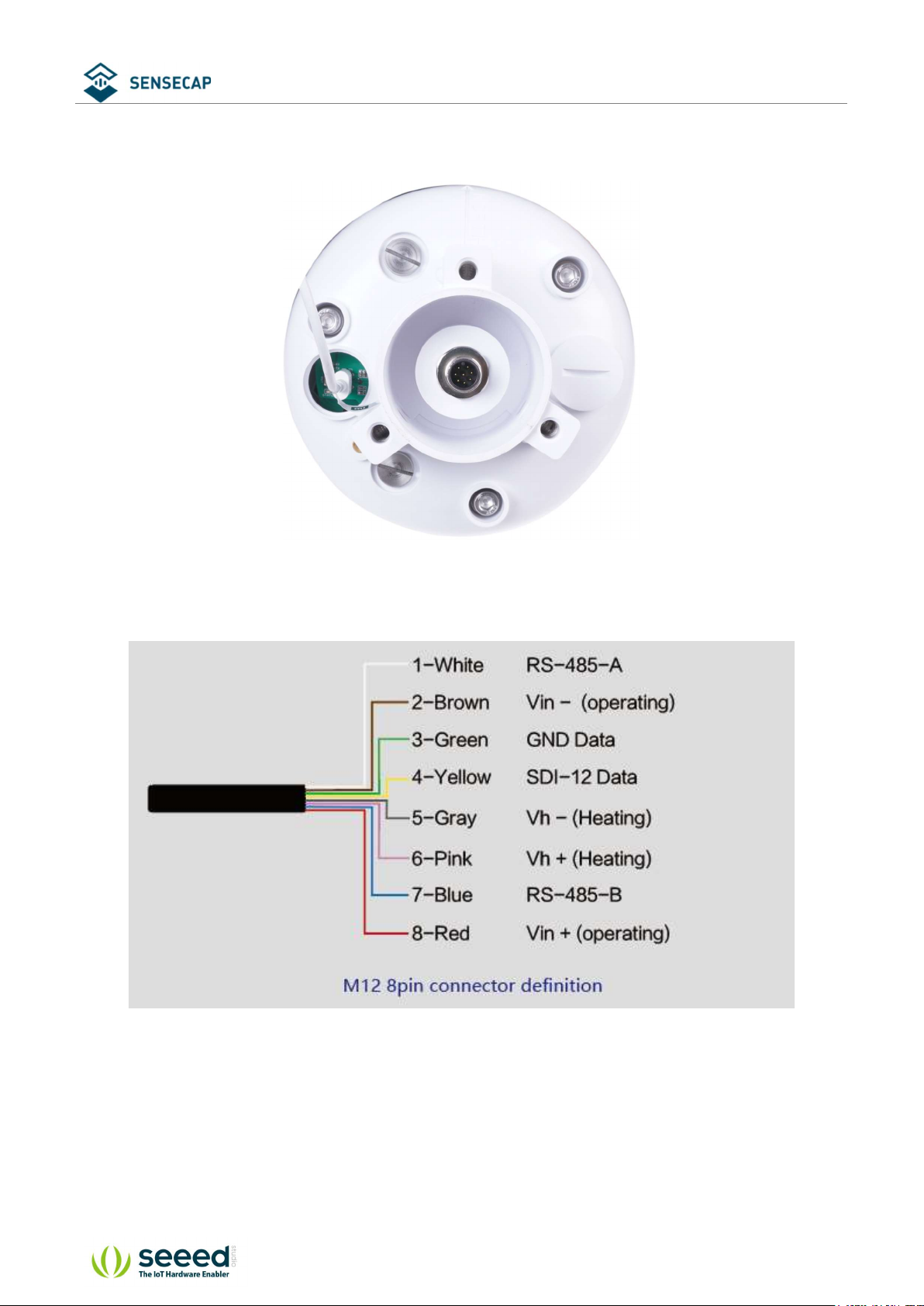
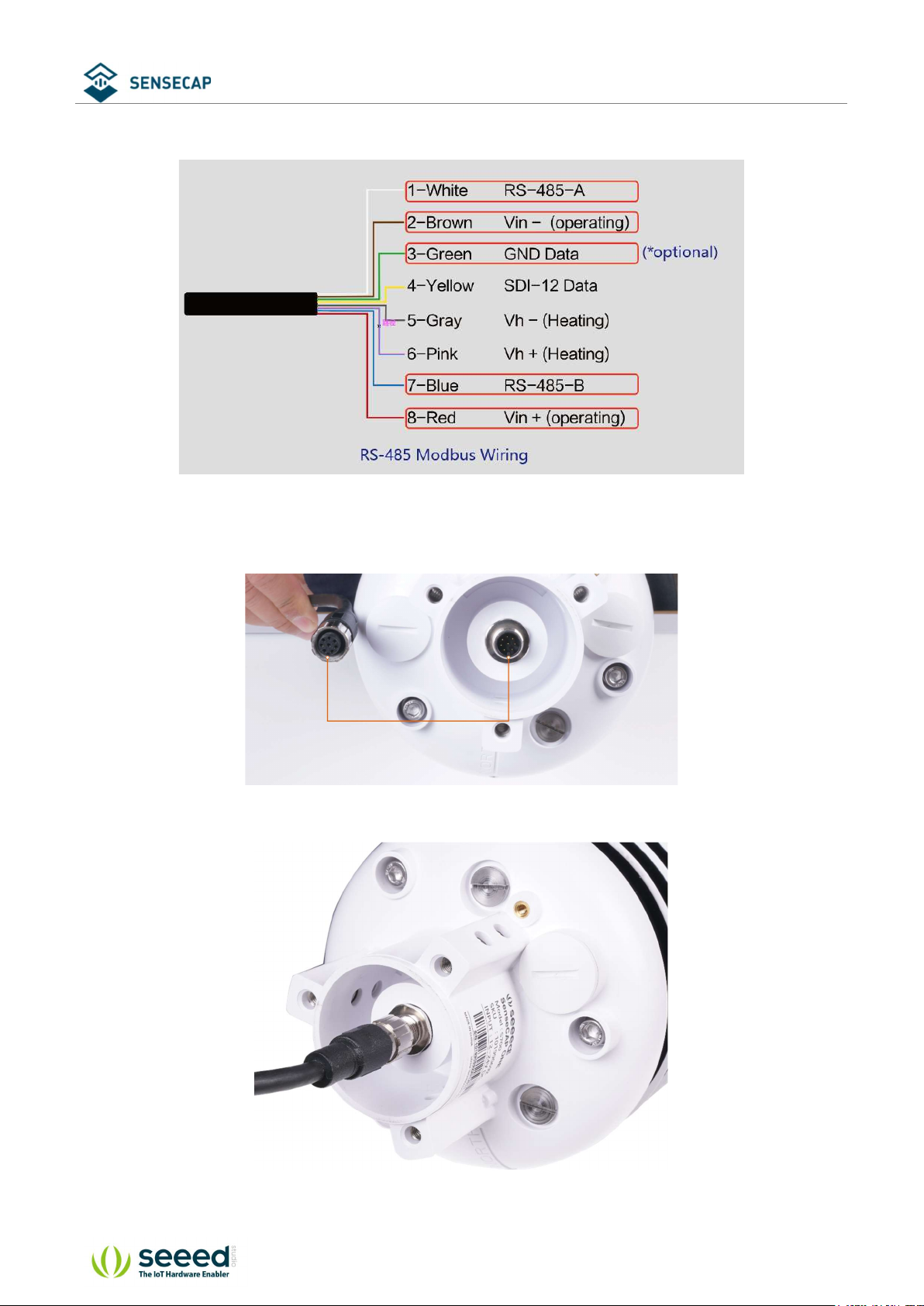
2.2.3 M12 Cable
The device adopts an M12 8-pin connector, the different colored pins provide power and data
communication (as shown in the above diagram).
When working with the RS-485, you can connect only 4 wires (not using a heating function), and
© 2008-2020 Seeed Technology Co., Ltd. All rights reserved. www.seeed.cc
The 10 Page total 50
User manual/ Technical information
the rest can be individually wrapped with tape to prevent short circuit
The holes of the cable and the pins of the device connector must be aligned when the cable is
plugged in.
Plugin the cable and tighten it clockwise
© 2008-2020 Seeed Technology Co., Ltd. All rights reserved. www.seeed.cc
The 11 Page total 50
User manual/ Technical information
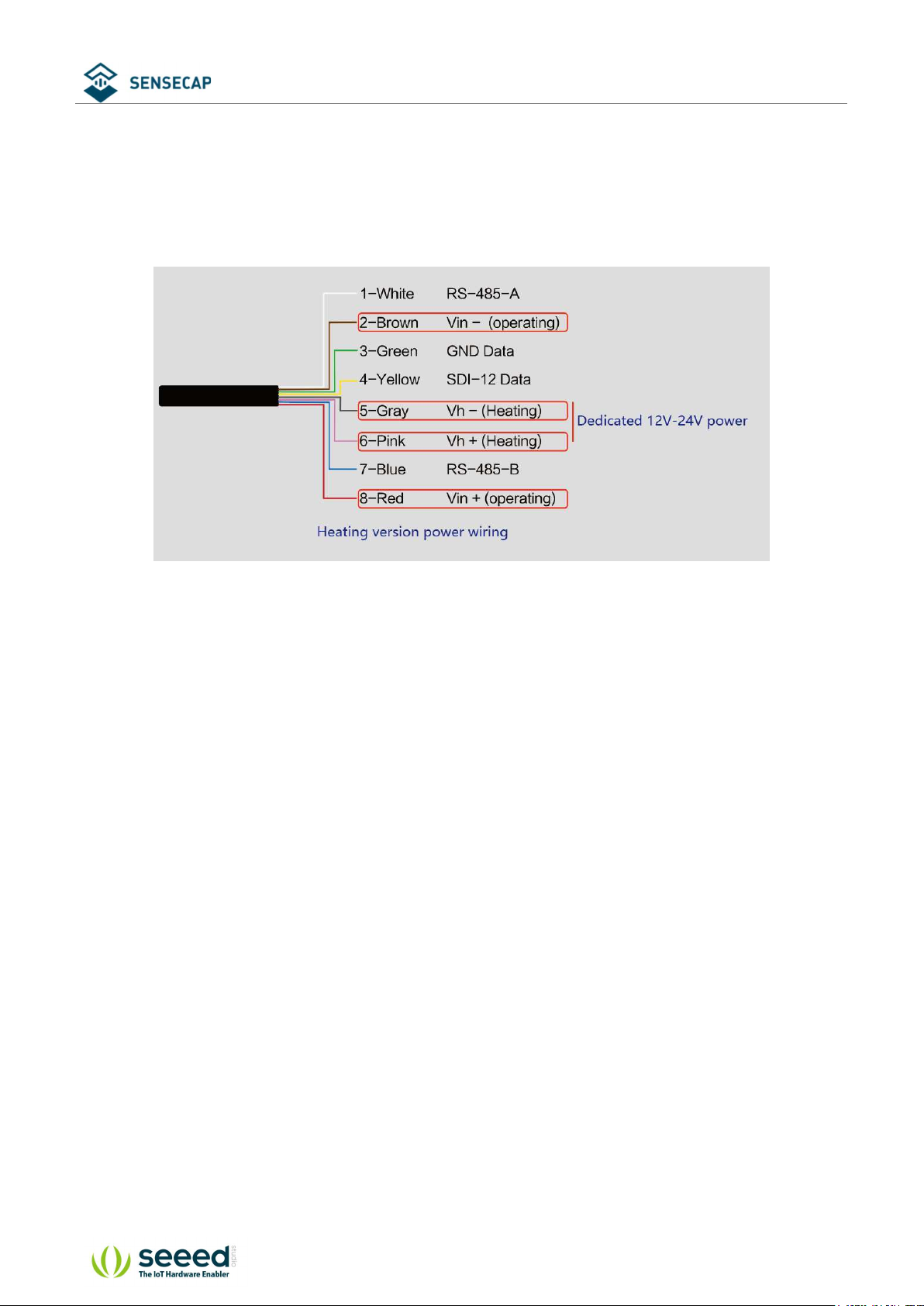
When using the device with a heating function, a separate 12V-24V (12V@2A is recommended)
power supply is required. Gray wire #5 is connected to the negative of the power supply, and
pink wire #6 is connected to the positive pole of the power supply.
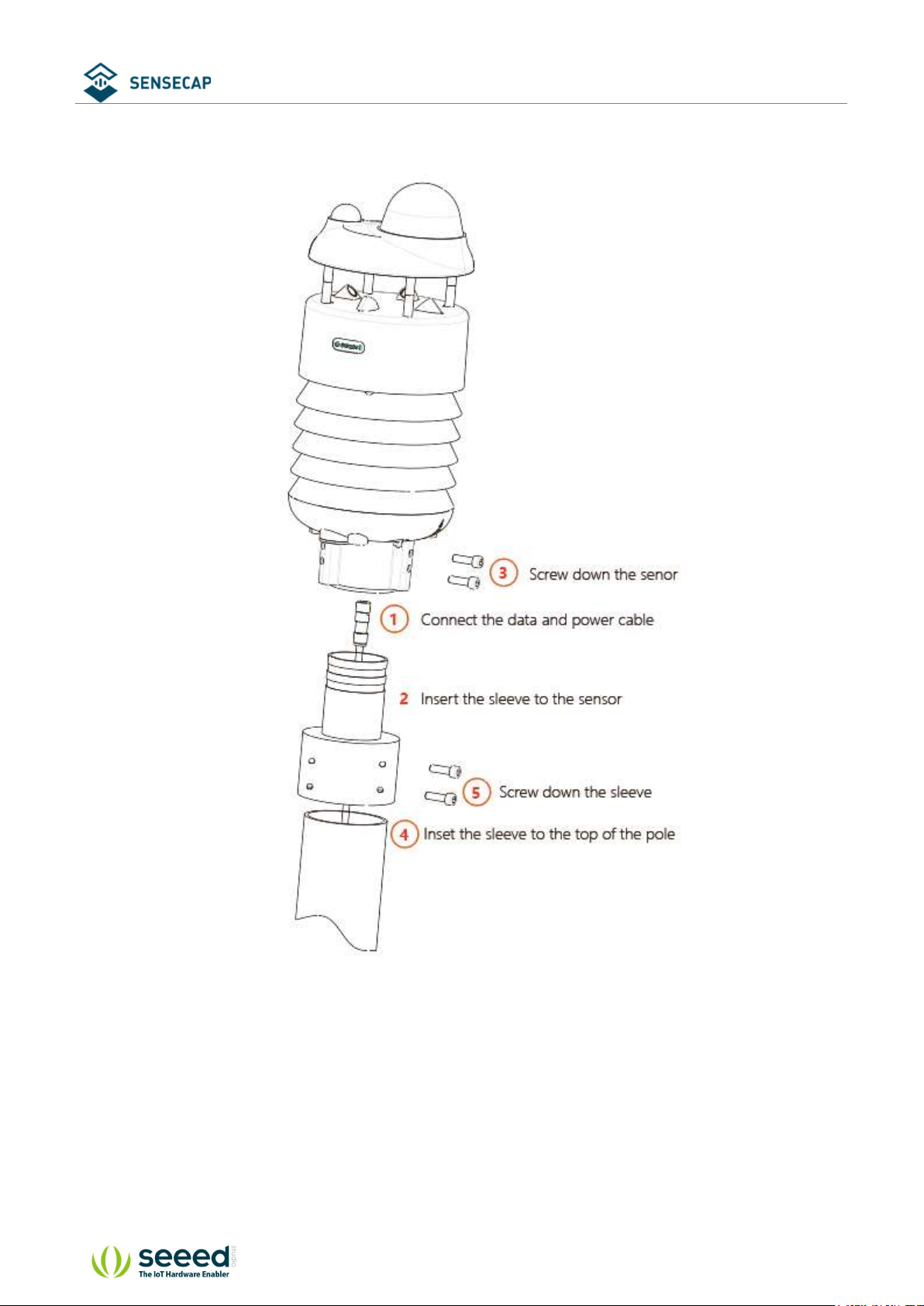
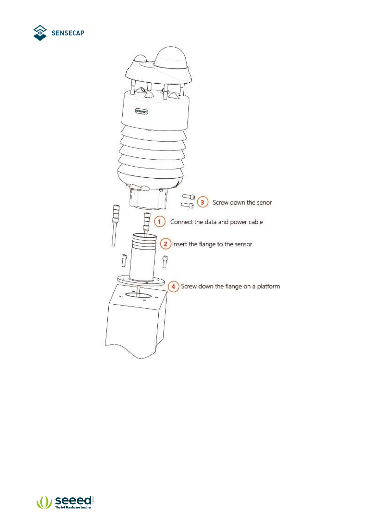
2.2.4 Install the device.
There are two major installation methods, either mount on a pole with a sleeve or a platform
with a flange plate.
© 2008-2020 Seeed Technology Co., Ltd. All rights reserved. www.seeed.cc
The 12 Page total 50
User manual/ Technical information
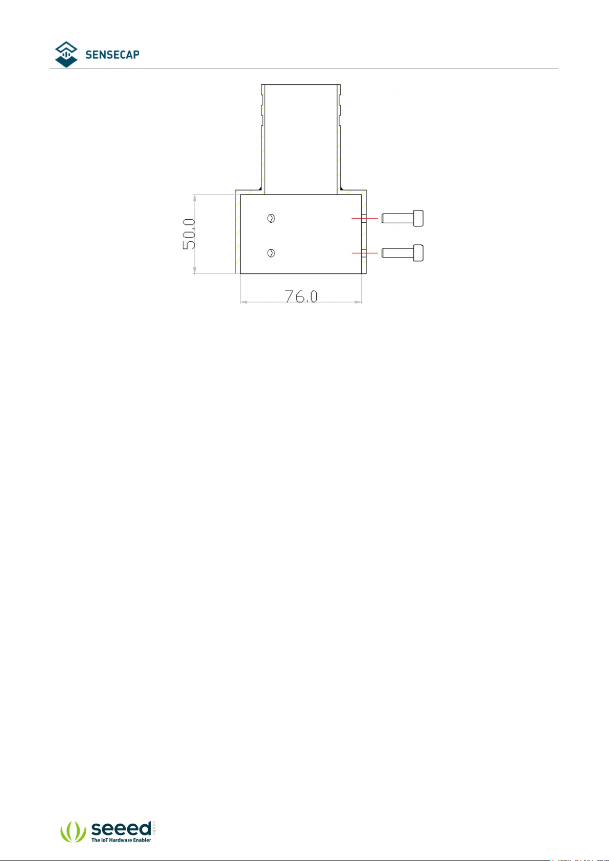
The size of the sleeve is shown below.
© 2008-2020 Seeed Technology Co., Ltd. All rights reserved. www.seeed.cc
The 13 Page total 50
User manual/ Technical information
It is recommended that the diameter of the pole should be less than or equal to 75cm.
© 2008-2020 Seeed Technology Co., Ltd. All rights reserved. www.seeed.cc
The 14 Page total 50
User manual/ Technical information
The dimension of the flange plate is shown below.
© 2008-2020 Seeed Technology Co., Ltd. All rights reserved. www.seeed.cc
The 15 Page total 50

User manual/ Technical information
© 2008-2020 Seeed Technology Co., Ltd. All rights reserved. www.seeed.cc
The 16 Page total 50

User manual/ Technical information
3 Device's Operating Mode
After installation, you can power on the device, configure it and collect data from the device.
The device has two operating modes, configuration mode, and working mode.
With a USB cable, you can check or configure the device’s
parameters, such as device name, version number, and
Configuration Mode
communication protocol configuration. Product firmware can be
upgraded in this mode.
Working Mode
Connect the devices and data logger with an M12 data and power
cable, and then the data collected by the device will be sent to the
host via different communication protocols.
© 2008-2020 Seeed Technology Co., Ltd. All rights reserved. www.seeed.cc
The 17 Page total 50

User manual/ Technical information
Configure the device via USB port
There is a waterproof round cover at the bottom of the device. Turn it counterclockwise to
remove this cover, and you can see a USB Type-C connector and a configuration button.
Connect the device to your computer with a USB Type-C cable. The computer will automatically
install the device driver. After the driver is successfully installed, you can see a serial port in the
device's manager.
If the driver is not installed automatically, click this link to manually download and install the
driver.
There are two methods to configure the device:
SenseCAP ONE Configuration Tool
Serial debug tool
© 2008-2020 Seeed Technology Co., Ltd. All rights reserved. www.seeed.cc
The 18 Page total 50

User manual/ Technical information
SenseCAP ONE Configuration Tool
SenseCAP ONE Configuration Tool offers a graphical interface for you to configure the device.
And you can download the tool from the GitHub link below:
https://github.com/Seeed-Solution/SenseCAP-One-Configuration-Tool/releases
Select the software for the respective operating system, Windows, macOS, or Linux based on
your needs.
The next image shows the main interface of the SenseCAP ONE Configuration Tool.
© 2008-2020 Seeed Technology Co., Ltd. All rights reserved. www.seeed.cc
The 19 Page total 50

User manual/ Technical information
1. Open the software, click on the pull-down box at the serial port, select the corresponding
serial port of the device.
2. Set the Baud rate to 9600.
3. Click connect, if the connection is successful, the sensor data area on the right will show the
corresponding measurements.
Click Settings to enter the device settings.
© 2008-2020 Seeed Technology Co., Ltd. All rights reserved. www.seeed.cc
The 20 Page total 50

User manual/ Technical information
1. Select the communication protocol. In the example here we choose the RS-485 Modbus RTU.
2. Modify the Modbus address: write the address in the Modbus address, and then click “Write
to Device”.
© 2008-2020 Seeed Technology Co., Ltd. All rights reserved. www.seeed.cc
The 21 Page total 50

User manual/ Technical information
On the configuration page, you can modify the following: device name, data type, and data
upload interval. After any modification, you will need to click “Write to Device” for the
changes to take effect.
In application settings, you can set the cycle for the tool to read sensor data, with the minimum
as 2S, and a dot range for the curve.
Click “Firmware Update” to update the device firmware. Please contact sales or technical
support at (sensecap@seeed.cc) to get the firmware.
© 2008-2020 Seeed Technology Co., Ltd. All rights reserved. www.seeed.cc
The 22 Page total 50

User manual/ Technical information
On the upgrade page, you will need to choose to update the mainboard firmware or the driver
board firmware. Select the firmware file at your local repository, click “Update Now”. If there is
an unexpected power break during the update process, the update won’t be executed. You will
need to go through the same process to update the firmware.
© 2008-2020 Seeed Technology Co., Ltd. All rights reserved. www.seeed.cc
The 23 Page total 50

User manual/ Technical information
Serial debug tool
The communication settings are as follows:
Select the serial port You can find port information in your computer's device manager
Baud rate 9600bps, 8 data bits, 1 stop bits, none parity, none flow control.
In the Serial Debug Assistant, select the corresponding COM port.
Check the "click Enter to start a new line" check box.
Set the baud rate to 9,600.
Send ? in the send area.
If you receive the corresponding 0XA message in the serial receive window, the
© 2008-2020 Seeed Technology Co., Ltd. All rights reserved. www.seeed.cc
The 24 Page total 50

User manual/ Technical information
configuration is successful. If not, please check the COM port and the baud rate.
Please check the detailed ASIIC command in the next chapter.
© 2008-2020 Seeed Technology Co., Ltd. All rights reserved. www.seeed.cc
The 25 Page total 50

User manual/ Technical information
4 Communication Protocols
The device supports the following communication protocols:
The Modbus protocol is a common language applied to
electronic devices. With this protocol, devices can communicate
within their network. It has become a universal industry standard,
widely used in data loggers, sensor equipment, and so on. Based on
Modbus-RTU
ASCII
this protocol, devices produced by different vendors can
communicate with each other for system integration.
The Modbus protocol is a master-slave protocol. One node is the
host, and the other nodes that use the Modbus protocol to join the
communication are the slave. Each slave has a unique address.
The ASCII protocol is a query-response or a question-and-answer
communication protocol in which a host PC uses ASCII characters to
send commands to a device and then receives responses from that
device.
Single-bus-based data communication protocol, is an
SDI-12
asynchronous serial communications protocol for intelligent sensors
that monitor environment data.
The 26 Page total 50
© 2008-2020 Seeed Technology Co., Ltd. All rights reserved. www.seeed.cc

User manual/ Technical information
Modbus-RTU Protocol
To start Modbus-RTU communication, the M12 data cable of the device needs to be connected
to the RS-485 port of one Data Logger, which powers up the device at a voltage of 12V-24V. The
following image is a diagram of the wiring:
Protocol communication parameters
Data Format One start bit, 8 Data bits, None parity, one Stop bits.
Baud Rate 9600bps (default), which can be modified by configuration.
Default Device Address 0x01
4.1.1 Modbus-RTU Protocol Message Format
Sensor data is stored in the Input Register and is read-only
The device address and the communication baud rate of RS-485 are stored in the Holding
Register and can be modified.
Each register is 16bits and takes up 2 bytes.
Read the message from the input register.
The message format from by the host
Slave address Function code Register address Number of registers CRC check
1 byte 1 byte 2 bytes (big-endian). 2 Byte (big-endian). 2 bytes
AA 0x04 RRRR NNNN CCCC
Address 0-247 0x04 big endian big endian little endian
© 2008-2020 Seeed Technology Co., Ltd. All rights reserved. www.seeed.cc
The 27 Page total 50

User manual/ Technical information
The message response from the slave
Slave address Function code Number of registers First Register data Second register data ... CRC check
1 byte 1 byte 1 byte 2 bytes 2 bytes ... 2 bytes
AA 0x04 MM VV0 VV1 ... CCCC
Address 0-247 0x04 big endian big endian big endian ... little-endian
Read and write the holding register.
The message format from by the host
Slave address Function code Register address Number of registers CRC check
1 byte 1 byte 2 bytes (big-endian). 2 Byte big-endian). 2 bytes
AA 0x03/0x06 RRRR NNNN CCCC
Address 0-247 0x03/06 big endian big endian little endian
The message response from the slave
Slave address Function code Number of
registers
1 byte 1 byte 1 byte 2 bytes 2 bytes ... 2 bytes
AA 0x03/0x06 MM VV0 VV1 ... CCCC
Address 0-247 0x03/0x06 big endian big endian big endian ... little-endian
First Register
data
Second register
data
... CRC check
Register
type
Input
register
4.1.2 Register Address Definition
Address Name values range
0x0000 Air temperature -40000~85000 2 R
0x0002 Air humidity 0~100000 2 R
0x0004
0x0006 Light intensity 0~188000000 2 R
0x0008
0x000A
0x000C
0x000E
0x0010
0x0012 Average wind 0~60000 2 R
barometric
pressure
Minimum wind
direction
Maximum wind
direction
Average wind
direction
Minimum wind
speed
Maximum wind
speed
30000000~125000000 2 R
0~360000 2 R
0~360000 2 R
0~360000 2 R
0~60000 2 R
0~60000 2 R
Number of
registers
Register
status
Note
big endian
Data format int32
Divide the data value by
1000 to get the true
measurements
The 28 Page total 50
© 2008-2020 Seeed Technology Co., Ltd. All rights reserved. www.seeed.cc

Holding
register
User manual/ Technical information
speed
0x0014
0x0016
0x0018 Rain intensity 0-80000 2 R
0x001A
0x1000 Device address 1 R/W
0x1001
0x2000 Set the
0x2001
Accumulated
rainfall
Accumulated
rainfall duration
Maximum
rainfall intensity
Baud rate
accumulated
rainfall to 0
Set the
accumulated
rainfall duration
to 0
0~80000 2 R
0~2000000 2 R
0-80000 2 R
The default address is 1
Can be set to 1 - 247
The default is 96, which
means 9600.
It can be set to:
12=1200
1 R/W Write 1 to set accumulated
1
1
R/W
R/W
24=2400
48=4800
96=9600
192=19200
384=38400
576=57600
1152=115200
rainfall to 0. Read back 1 to
confirm that the setting is
finished. Read back 0
indicates that the setting
failed
Write 1 to set accumulated
rainfall duration to 0. Read
back 1 to confirm that the
setting is finished. Read back
0 indicates that the setting
failed
4.1.3 Modbus-RTU Read
Here is an example of the Modbus Poll tool
(download from https://www.modbustools.com/download.html).
© 2008-2020 Seeed Technology Co., Ltd. All rights reserved. www.seeed.cc
The 29 Page total 50

User manual/ Technical information
Configuration connection parameters: Baud rate 9600bps, 8 Data bits, None Parity, 1 Stop bits.
Read the air temperature register 0x0000 to 0x0001, click Setup, and select Read/Write
Definition
© 2008-2020 Seeed Technology Co., Ltd. All rights reserved. www.seeed.cc
The 30 Page total 50

User manual/ Technical information
Set the default slave ID to 1, function code 04, starting address 0, quantity 2
Now the computer reads the sensor data every 1 second, and the measurement (line 0 and line
1) is shown in below picture, after dividing the measurement by 1000, it is the true temperature
value, 28300/1000 = 28.3 °C
On the right, you can check the raw sent and received data packages.
When the temperature is positive:
1. Host sends 01 04 00 00 00 02 71 CB
2. Slave responses 01 04 04 00 00 6E 8C D6 41
3. Return temperature data 0x00006E8C (Hex), converted to decimal = 28300, get the
corresponding air temperature by dividing through 1000, air temperature = 28300/1000 =
© 2008-2020 Seeed Technology Co., Ltd. All rights reserved. www.seeed.cc
The 31 Page total 50

User manual/ Technical information
28.3 °C
When the temperature is negative:
The temperature needs to be obtained through a complement calculation.
1. Host sends 01 04 00 00 00 02 71 CB
2. Slave responses 01 04 04 FF FF FC 18 D6 41
3. Returned temperature data FFFFFC18H (Hex complement).
4. The original code is - (FF FF FC 18-1 = FF FF FC 17) = 80 00 03 E8(Hex) = -1000 (Decimal).
5. Then the temperature measurement is -1000/1000 = -1°
© 2008-2020 Seeed Technology Co., Ltd. All rights reserved. www.seeed.cc
The 32 Page total 50

User manual/ Technical information
ASCII Protocol
4.2.1 Command definition
A Device address, 0 by default
XA Starter, fixed value
; The separator used to distinguish multiple commands
... A command, represented by different strings
? A query term used to query values
= Assignment, which is used to set the value
v The argument, the specific value of the parameter is set
m Sensor measurement
Sensor measurements combine character for getting or setting
&
multiple measurement parameters
<CR><LF> Response terminator
Terms Explanation
Represented by different strings, such as BD for Baud rate and CP for
Command
communication protocol
A Data List contains multiple sensor measurement types, represented
by an abbreviation of G0.
Data List
For example, G0 contains several test types:
AT;AH;AP;LX;DN;DM;DA;SN;SM;SA;RA;RD;RI;RP;HT;TILT
© 2008-2020 Seeed Technology Co., Ltd. All rights reserved. www.seeed.cc
The 33 Page total 50

User manual/ Technical information
4.2.2 Query Command Format
Commands come in two formats:
1. A command without = refers to the basic query method.
Example: ?<CR><LF> indicates query the device’s address
2. A command with = refers to a query with an argument
Example: 0XA;BD=?<CR><LF> indicates query the device’s baud rate
4.2.3 Setting Command Format
Set a specified parameter, such as setting a baud rate.
Example: 0XA;BD=96<CR><LF> indicates query the device’s baud rate
4.2.4 Command List
Device info queries and related commands settings
Query Device address ?
Send ?<CR><LF>
Query
Query baud rate BD
Query Send 0XA; BD=?<CR><LF>
Response 0XA<CR><LF>
Description The default response address is 0
The 34 Page total 50
© 2008-2020 Seeed Technology Co., Ltd. All rights reserved. www.seeed.cc

User manual/ Technical information
Response 0XA; BD=96<CR><LF>
Description The baud rate for device 0 is 9,600
Send 0XA; BD=[bd]<CR><LF>
Response 0XA; BD=[bd]<CR><LF>
Setting
Description
Communication protocol CP
Send 0XA; CP=?<CR><LF>
Response 0XA; CP=[cp]<CR><LF>
Query
Description
Send 0XA; CP=[cp] <CR><LF>
Setting
Query
Setting
Query
Setting
Response 0XA; CP=[cp] <CR><LF>
Description
RS-485 address MBAD
Send 0XA; MBAD=?<CR><LF>
Response 0XA; MBAD=1<CR><LF>
Description The RS-485 address of device 0 is 1 (decimal)
Send 0XA; MBAD=2<CR><LF>
Response 0XA; MBAD=2 <CR><LF>
Description Set the address of device 0 to 2 (decimal)
RS-485 baud rate MBBD
Send 0XA; MBBD=?<CR><LF>
Response 0XA; MBBD=96<CR><LF>
Description
Send 0XA; MBBD=[bd]<CR><LF>
Response 0XA; MBBD=[bd]<CR><LF>
Description Return device 0’s RS-485 communication baud rate is [bd]: it can be 96 for 9600, 192 for 19200,
Return the Baud rate of device 0 is [bd], it could be 96 for 9600; 192 for 19200, 384 for 38400;
576 for 57600; and 1152 for 115200.
For example, the return value 0XA;BD=96 represents the successful setting of a Baud rate of
9,600
[cp] Represents the code of the communication protocol, the device supports multiple
communication protocols.
1 SDI-12
2 RS-232 Modbus-RTU
3 RS-485 Modbus-RTU
4 RS-422 Modbus-RTU
5 RS-232 ASCII
6 RS-485 ASCII
7 RS-422 ASCII
Response 0XA;CP=3<CR><LF> means that the data communication protocol of device 0 is
Modbus-RTU protocol based on the RS-485 bus
Set the communication protocol of device 0 to [cp], if [cp] is 6, the communication protocol is set
to ASCII text protocol based on the RS-485 bus
The RS-485 communication baud rate for device 0 is 9,600
The 35 Page total 50
© 2008-2020 Seeed Technology Co., Ltd. All rights reserved. www.seeed.cc

User manual/ Technical information
384 for 38400, 576 for 57600, and 1152 for 115200.
For example, the return value is 0XA;MBBD=96 represents the successful setting of the baud rate
of 9,600
Device Name NA
Send 0XA; NA=?<CR><LF>
Query
Setting
Query
Query
Query
Query
Setting
Query
Setting
Response 0XA; NA=SenseCAP ONE S700<CR><LF>
Description Device name is: SenseCAP ONE S700
Send 0XA; NA=[na]<CR><LF>
Response 0XA; NA=[na] <CR><LF>
Description Set the new device name to [na], and the character length limitation is 64 bytes
Device model TP
Send 0XA; TP=?<CR><LF>
Response 0XA; TP=SenseCAP ONE S700<CR><LF>
Description The device model is SenseCAP ONE S700
Device version VE
Send 0XA; VE=?<CR><LF>
Response 0XA; VE=HW-1.0&SW-2.0&S1-2.2<CR><LF>
Description
Device serial number S/N
Send 0XA; S/N=?<CR><LF>
Response 0XA; S/N=1019906922012011<CR><LF>
Description S/N represents the serial number of the device
Production date MD
Send 0XA; MD=?<CR><LF>
Response 0XA; MD=20201027<CR><LF>
Description The production date of the return device is October 27, 2020, 20201027
Restore configuration RESTORE
Send 0XA; RESTORE=1<CR><LF>
Response 0XA; RESTORE=1<CR><LF>
Description Return 0XA; RESTORE=1 means the setting is successful and return 0XA means the setting fails.
Electronic Compass CC
Send 0XA;CC=?<CR><LF>
Response 0XA;CC=[cc]<CR><LF>
Description
Send 0XA;CC=Y<CR><LF>
Response 0XA;CC=Y<CR><LF>
Description Enable Electronic Compass
Send 0XA;CC=N<CR><LF>
Response 0XA;CC=N<CR><LF>
Device hardware(HW) is v1.0, the software firmware(SW) is v2.0, and the #1 driver board
firmware is v2.2
[cc] Electronic Compass offset state
Y Enable Electronic Compass
N Disable Electronic Compass
C Enable Geomagnetic compensation
The 36 Page total 50
© 2008-2020 Seeed Technology Co., Ltd. All rights reserved. www.seeed.cc

User manual/ Technical information
Description Disable Electronic Compass
Send 0XA;CC=C<CR><LF>
Response 0XA;CC=C<CR><LF>
Enable Geomagnetic compensation,it will start the 30s compensation process, during this time,
the device should be placed horizontally, and rotate evenly along the Z-axis for 1-2 rounds.
Y: Enable tilt detection function
N: Disable tile detection function
Set to enable tilt detection function:TILT=0 means the device is placed vertically, TILT=1 means
the device is placed not placed upright.
Y: Enable heating function
N: Disable heating function
Set to enable heating function.
When the air temperature is between [5℃, -25℃], the equipment starts to heat up, and the heating
plate heating temperature can go up to 40℃
When the air temperature is greater than 5°C or less than -25°C, the equipment stops heating.
Note: the heating function need extra dedicate 12V-2A power sourcing
Query
Setting
Query
Setting
Description
Tilt Detect TD
Send 0XA;TD=?<CR><LF>
Response 0XA;TD=Y/N<CR><LF>
Description
Send 0XA;TD=Y<CR><LF>
Response 0XA;TD=Y<CR><LF>
Description
Send 0XA;TD=N<CR><LF>
Response 0XA;TD=N<CR><LF>
Description Disable tile detection function:the TILT always equals 0 when the device is placed at any position.
Heating HC
Send 0XA; HC =?<CR><LF>
Response 0XA; HC =Y/N<CR><LF>
Description
Send 0XA;HC=Y<CR><LF>
Response 0XA;HC=Y<CR><LF>
Description
Send 0XA;HC=N<CR><LF>
Response 0XA;HC=N<CR><LF>
Description Set to enable heating function.
Command to read sensor data.
For quick reading of all measurements, G0 is the command.
Read all measurements G0
Send 0XA; G0?<CR><LF>
Query
Response
Description Returns the value of all measurement parameters
0XA;AT=23.6;AH=56.4;AP=100819.1;LX=93.0;DN=0.0;DM=0.0;DA=0.0;SN=0.0;SM=0.0;SA=0.0;RA
=1.4;RD=60.0;RI=0.0;RP=0.0;HT=-38.4;TILT=0.0<CR><LF>
© 2008-2020 Seeed Technology Co., Ltd. All rights reserved. www.seeed.cc
The 37 Page total 50

User manual/ Technical information
Group
Name
G0
Measurement Name Unit
Contains all combinations of measurement parameters
AT Air temperature ℃ (default), ℉
AH Air humidity %RH
AP Barometric pressure Pa (default), hPa, bar, mmHg, inHg
LX Light intensity Lux
DN Minimum wind direction deg
Dm Maximum wind direction deg
DA Average wind direction deg
SN Minimum wind speed m/s (default), km/h, mph, knots
SM Maximum wind speed m/s (default), km/h, mph, knots
SA Average wind speed m/s (default), km/h, mph, knots
RA Accumulated rainfall mm (default), in
RD Duration of rainfall s
RI Rainfall intensity mm/h (default), in/h
Rp Maximum rainfall intensity mm/h (default), in/h
HT Heating temperature ℃
TILT Fall detection
Modify the Properties of Measurement Parameters
Properties represent some characteristics of the measured data, such as the unit of output
temperature and the interval between data updates.
Temperature and Humidity
Data Update Interval
Send 0XA;IB=? <CR><LF>
Query
Setting
Air Temperature Unit UT
Query
Set up
Barometric Pressure Unit UP
Response 0XA;IB=1<CR><LF>
Description The default data updates every 1 second
Send 0XA;IB=2<CR><LF>
Response 0XA;IB=2<CR><LF>
Description Set the data update interval to 2 seconds, you can choose a value between 1 to 3600 seconds.
Send 0XA; UT=? <CR><LF>
Return 0XA; UT=C<CR><LF>
Description The temperature unit is Celsius
Send 0XA; UT=F<CR><LF>
Response 0XA; UT=F<CR><LF>
Description
IB
Set the air temperature unit to Fahrenheit.
C=°C, F=°F
The 38 Page total 50
© 2008-2020 Seeed Technology Co., Ltd. All rights reserved. www.seeed.cc

User manual/ Technical information
Send 0XA; UP=? <CR><LF>
Query
Set up
Wind Speed & Direction Data
Update Interval
Query
Set up
Wind speed & direction
average time window
Query
Setting
Wind Speed Unit US
Query
Setting
The wind direction offset
correction value
Query
Setting
Rainfall Data Update Interval IR
Response 0XA; UP=P<CR><LF>
Description The unit is Pa.
Send 0XA; UP=H<CR><LF>
Response 0XA; UP=H<CR><LF>
Description
Send 0XA; IW=? <CR><LF>
Response 0XA; IW=1<CR><LF>
Description The default data updates every 1 second.
Send 0XA; IW=2<CR><LF>
Response 0XA; IW=2<CR><LF>
Description Set the data update interval to 2 seconds, you can choose a value between 1 to 3600 seconds.
Send 0XA; AW=? <CR><LF>
Response 0XA; AW=5<CR><LF>
Description
Send 0XA; AW=10<CR><LF>
Response 0XA; AW=10<CR><LF>
Description Set the data update interval to 10 seconds, you can choose a value between 1 to 3600 seconds
Send 0XA; US=? <CR><LF>
Response 0XA; US=M<CR><LF>
Description The default wind speed unit is m/s
Send 0XA; US=K<CR><LF>
Response 0XA; US=K<CR><LF>
Description
Send 0XA;DO=? <CR><LF>
Response 0XA; DO=0<CR><LF>
Description The default correction angle for the wind direction is 0.
Send 0XA; DO=1<CR><LF>
Response 0XA; DO=1<CR><LF>
Description
Set the unit to hPa.
P = Pa, H = hPa, B = bar, M = mmHg, I=inHg
IW
AW
The default average update interval for wind speed & direction data is 5 seconds.
The device collects wind speed & direction in 5s intervals and then averages the value.
Set unit to km/h
M = m/s, K = km/h, S = mph, N = knots
DO
Set the wind direction offset to +10°, if the current wind direction is 280°, the corrected wind
direction is 290 degrees.
The wind correction range is -180° to 180°
The 39 Page total 50
© 2008-2020 Seeed Technology Co., Ltd. All rights reserved. www.seeed.cc

User manual/ Technical information
Send 0XA;IR=? <CR><LF>
Query
Setting
Rainfall Unit UR
Query
Setting
Rainfall Counter Reset Mode CR
Query
Setting
Accumulated rainfall overflow
value
Query
Setting
Accumulated rainfall duration
overflow value
Query
Response 0XA;IR=10<CR><LF>
Description The default rain data update interval is 10 seconds.
Send 0XA;IR=60<CR><LF>
Response 0XA;IR=60<CR><LF>
Description
Send 0XA; UR=? <CR><LF>
Response 0XA; UR=M<CR><LF>
Description The default rainfall unit is mm
Send 0XA; UR=I<CR><LF>
Response 0XA; UR=I<CR><LF>
Description
Send 0XA; CR=? <CR><LF>
Response 0XA; CR=M<CR><LF>
Description Rain counter reset mode is by manual M
Send 0XA; CR=L<CR><LF>
Response 0XA; CR=L<CR><LF>
Description
Send 0XA; AL=? <CR><LF>
Response 0XA; AL=80000<CR><LF>
Description
Send 0XA; AL=1000<CR><LF>
Response 0XA; AL=1000<CR><LF>
Description
Send 0XA; DL=? <CR><LF>
Response 0XA; DL=2000000<CR><LF>
Set the data update interval to 60seconds.
The interval range is 10 to 3600 seconds.
Set the units of rainfall to inches
M = mm, I = inch.
Set the counter reset mode to overflow reset, and you can select the modes as:
M: Manual reset, reset immediately after sending the reset command (the reset command is
available under all three communication protocols, as detailed in the different protocol sections).
A: Post-read reset (accumulated rainfall and accumulated rainfall time are performed separately
after reading reset)
L: Overflow reset
AL
The default accumulated rainfall overflow value is 80000, which is measured in the current
rainfall unit.
This overflow value takes effect only if the CR rainfall counter reset mode is set to L overflow
reset.
When the rainfall is set to 1000 (current unit), the accumulated rainfall will be reset to 0.
The overflow value range is 10-80000 (current unit).
DL
The 40 Page total 50
© 2008-2020 Seeed Technology Co., Ltd. All rights reserved. www.seeed.cc

User manual/ Technical information
The default rainfall duration overflow value is 2,000,000, the unit is second.
Description
Send 0XA; DL=3600<CR><LF>
Setting
Clear the accumulated rainfall CRA
Setting
Clear accumulated rainfall
Duration
Setting
Response 0XA; DL=3600<CR><LF>
Description
Send 0XA; CRA=1<CR><LF>
Response 0XA; CRA=1<CR><LF>
Description Clear the accumulated rainfall.
Send 0XA; CRD=1<CR><LF>
Response 0XA; CRD=1<CR><LF>
Description Clear the accumulated rainfall duration.
This overflow value will only take effect when the CR rainfall counter reset mode is L overflow
reset.
Set the rainfall duration overflow value to 3600 seconds.
It ranges between 100 – 2000000 seconds.
CRD
The 41 Page total 50
© 2008-2020 Seeed Technology Co., Ltd. All rights reserved. www.seeed.cc

User manual/ Technical information
SDI-12
SDI-12 communication adopts three wires, two of which are sensor power supply wires and the other is
SDI-12 signal wire.
Each sensor on the SDI-12 bus has a unique address, which can be set to ‘0’, ‘1’ ~ ‘9’, ‘A’ ~ ‘Z’, ‘A’ ~ ‘Z’.
The SDI-12 address of the SenseCAP ONE defaults to ‘0’. The instructions supported by this sensor are
shown in the next chapter, where each instruction conforms to the SDI-12 v1.4.
The sensor is powered by a DC power supply of 3.6~16V. After the sensor is powered on, it will go into
sleep mode immediately and wait for the data acquisition equipment to give instructions. SDI-12 uses baud
rate 9600bps, 1 start bit (high level), 7 data bits (high 0 and low 1, anti-logic), 1 even parity bit, and 1 stop
bit.
The sequence of each byte sent is shown in the following figure:
4.3.1 SDI-12 command and response
Command format
Start with device address ‘a’, it is ‘0’in the following sample.
End with ‘!’as a terminator
The response command end with the <CR><LF>
Query the device
address
Send ?!
Response 0<CR><LF>
Description The sensor at address '0' responded to the query
Query the device
status
Send 0!
Response 0<CR><LF>
Description Address '0' of device online
Query the device
information
Send 0I!
?!
0!
0I!
© 2008-2020 Seeed Technology Co., Ltd. All rights reserved. www.seeed.cc
The 42 Page total 50

User manual/ Technical information
Response 014SenseCAPONE3.01019906922104001<CR><LF>
Response the device information
accccccccmmmvvvxxxxxxxxxxxxxxxx<CR><LF>
a Device address: 0
14 SDI-12 protocol version :v1.4
Description
cccccccc Product:SenseCAP
mmm Device series:ONE
vvv Software version:3.0
xxxxxxxxxxxxxxxx Device serial number:1019906922104001
Modify device
0Ab!
address
Send 0A1!
Response 1<CR><LF>
Description Device address 0 is changed to 1. The address range is 0-9、A-Z、a-z.
Start Measurement
Send 0M!
Response
Description
Extended
Measurement
Send 0Mn!(n ranges 0~9)
Response
Description
0M!
Immediately response:00024<CR><LF>
After 2s, the response device’s address, means finishing the measurement.:0<CR><LF>
This command is to start THPL measurement, in order: air temperature, air humidity, atmospheric
pressure, illuminance, but the sensor will not reply to the measurement data immediately after
receiving this command, but the time required to reply the measurement data and the number
of measurements. To obtain measurement data, you must wait until the measurement is
completed, and then use the send data command “0D0!” to obtain it.
After using this command, the sensor will enter a sleep mode after the measurement to save
power consumption. After using "continuous measurement command 0R0!...0R9!", it will exit the
low power consumption state.
The response format is defined as follows:
atttn<CR><LF>
a Device address:0
ttt The time expense to measure data, the unit is
seconds.
n The number of measurements
0M1!...0M9!
Immediately response:00024<CR><LF>
After 2s, the response device’s address, means finishing the measurement.:0<CR><LF>
0M1!: Start Wind measurement: minimum wind direction, maximum wind direction, average
wind direction, minimum wind speed, maximum wind speed, average wind speed.
0M2!: Start Rain measurement: accumulated rainfall, accumulated rainfall time, rainfall
intensity, maximum rainfall intensity.
0M3!: Start Dust measurement: PM2.5, PM10.
0M9!: Start other measurements: heating temperature, tilt status.
The 43 Page total 50
© 2008-2020 Seeed Technology Co., Ltd. All rights reserved. www.seeed.cc

User manual/ Technical information
0M4!...0M8!: reserved.
After using this command, the sensor will enter a sleep mode after the measurement to save
power consumption. After using "continuous measurement command 0R0!...0R9!", it will exit the
low power consumption state.
For the definition of reply, please refer to "Start measurement command 0M!"
Read
0D0!...0D9!
measurement
value
Send 0D0!
Response 0+27.65+65.81+100000+5000<CR><LF>
This command is used to obtain a set of measurement data in the sensor. The sensor responds
with the measurement data. If all the desired measurement data is not returned in 0D0!, you can
continue to send 0D1!, 0D2!, etc., until all the measurement data is received.
The response format is defined as follows:
a<values><CR><LF>
a Device address:0
<values> This the real measurement value.
Description
Continuous
measurement
command
Send 0R0!
Response 0+27.65+65.81+100000+5000<CR><LF>
Description
0R0!..0R9!
This is different from "start measurement command 0M!", the measurement value can be
returned directly. Each "continuous measurement command" is an independent measurement
process, for example, 0R0! and 0R1! are not required before 0R2!.
0R0!: Start continuous THPL measurement: air temperature, air humidity, atmospheric pressure,
light intensity.
0R1!: Start Wind continuous measurement: minimum wind direction, maximum wind direction,
average wind direction, minimum wind speed, maximum wind speed, average wind speed.
0R2!: Start Rain measurement: accumulated rainfall, accumulated rainfall time, rainfall intensity,
maximum rainfall intensity.
0R3!: Start Dust continuous measurement: PM2.5, PM10.
0R9!: Start another Continuous measurement: heating temperature, dumping status.
0R4!...0R8!: reserved.
If the sensor was in a low-power working state before, after using this command, the sensor will
pd.d
p is the polarity symbol.
the first d is the number before the decimal point.
the second d is the data after the decimal point.
Note that the decimal point is not necessary.
In this example, "+27.65" is the first measurement data, "+65.81" is the
second measurement data, "+100000" is the third measurement data,
and "+5000" is the fourth measurement data.
The 44 Page total 50
© 2008-2020 Seeed Technology Co., Ltd. All rights reserved. www.seeed.cc

User manual/ Technical information
exit the low-power working state.
Start Measurement
with CRC
Send 0RC0!
Response 0+26.52+67.73+100280+35JKy
Description
Clear accumulated
rainfall command
Send 0XCRA!
Response 01<CR><LF>
Description
Clear accumulated
rainfall duration
Send 0XCRD!
Response 01<CR><LF>
Description
aMC!,aMC1!...aMC9!,aRC0!...aRC9!
To enhance the error detection capability of the SDI-12 protocol, "start measurement
command 0M!", "extended measurement command 0M1!..0M9!" and "continuous
measurement command 0R0!...0R9!" can add 16-bit cyclic redundancy check. Add the
character C after the command character M or R of these commands to form a new command:
aMC!,aMC1!...aMC9!,aRC0!...aRC9!.
For the calculation of CRC-16, please refer to the SDI-12 protocol v1.4 document.
0XCRA!
aN<CR><LF>
a Device address:0
N Clear success: 1
Clear failed: 0
0XCRD!
aN<CR><LF>
a Device address:0
N Clear success: 1
Clear failed: 0
4.3.2 SDI-12 Read
Wiring the SDI-12
Use USB to SDI-12 debugger to communicate with the device
© 2008-2020 Seeed Technology Co., Ltd. All rights reserved. www.seeed.cc
The 45 Page total 50

User manual/ Technical information
The communication settings:
Format 1 start bits, 7 data bits, Even parity, 1 stop bits
Baud rate 1200bps
Device address 0x00
Connect the green wire (GND Data) and yellow wire (SDI-12 Data) to the USB to SDI-12 debugger.
And connect the red wire (Vin+ power positive) and brown wire (Vin- power ground) to the 12V
power supply.
Download the serial port debugging assistant: https://github.com/Neutree/COMTool,and then
open the serial port debugging tool.
Choose the correct port number
Set the baud rate to the baud rate of the USB to SDI-12 debugger (note that it is not the baud
rate of the SDI-12 protocol)
Check the "CRLF"
Click to open the serial port.
Send the query device address command "?!", if you can see the response "0", it means the
connection is OK.
The 46 Page total 50
© 2008-2020 Seeed Technology Co., Ltd. All rights reserved. www.seeed.cc

User manual/ Technical information
Start Measurement
Read air temperature, air humidity, barometric pressure, light intensity
Send the "start measurement command 0M!", the sensor first responds with "00024", which means
that the "0M!" command takes 2 seconds to measure and returns 4 measured values. After 2
seconds, the sensor responds with its own address "0", indicating that the measurement has been
completed.
Then send " Read measurement value command 0D0!" to get the 4 measured values of this
© 2008-2020 Seeed Technology Co., Ltd. All rights reserved. www.seeed.cc
The 47 Page total 50

User manual/ Technical information
measurement, which are air temperature +27.01℃, air humidity 64.74%, barometric pressure
100720Pa, and light intensity 10Lux.
Use extended measurement command 0M1! to read minimum wind direction, maximum wind
direction, average wind direction, minimum wind speed, maximum wind speed, average wind
speed. The device responds with "00056", which means that the "0M1!" command takes 5
seconds to measure and returns 6 measured values. After 5 seconds, the device responds with its
own address "0", indicating that the measurement has been completed.
© 2008-2020 Seeed Technology Co., Ltd. All rights reserved. www.seeed.cc
The 48 Page total 50

User manual/ Technical information
Then send " Read measurement value command 0D0!" to get the 6 measured values of this
measurement, which are minimum wind direction 345.9 degrees, maximum wind direction 347.5
degrees, average wind direction 346.3 degrees, minimum wind speed 2.8m/s, and maximum wind
speed 2.8m. /s, average wind speed 2.8m/s.
Then send “continuous measurement command 0R2!, the device returns 4 measured values:
cumulative rainfall 1.2mm, cumulative rainfall duration 20 seconds, rainfall intensity 1.2mm/h,
maximum rainfall intensity 72.0mm/h.
© 2008-2020 Seeed Technology Co., Ltd. All rights reserved. www.seeed.cc
The 49 Page total 50

User manual/ Technical information
6 Error code
Modbus error code
Error code Description Response instance
0x01 Device do not response 01 84 01 82 C0
0x04 Sensor probe exception 01 84 04 42 C3
ASCII error code
Error code Description Response instance
0 Command do not exist 0XA;...=#0
1 Device do not response 0XA;AT=#1
3 The command length exceeds the limit, it
4 Sensor probe exception 0XA;AT=#4
0XA;…=#3
needs to be reduced
SDI-12 error code
Error code Description Response instance
2001001 Device do not response 0+2001001+2001001+2001001+2001001<CR><LF>
2001004 Sensor probe exception 0+2001004+2001004+2001004+2001004<CR><LF>
© 2008-2020 Seeed Technology Co., Ltd. All rights reserved. www.seeed.cc
The 50 Page total 50
 Loading...