


Stand Alone Type
USER’S
MANUAL
DVR
SYSTEM
041130
050530
041231 050315 050404
050609
Revision Date : 2005. 06. 09.
Firmware 2.4 Version
Ex-Factory Date :
050525050511

• MANUAL CHANGE LIST
♦ Manual is Updated as Below.
1. Server DVR
① PTZ Control (p.26)
* PRESET Function Add : PELCO-D PROTOCOL
* SWING Function Add : DONGYANG CAMERA (D-MAX)
F/W VER. 1.6
Amend Date : 2004.11.30
F/W VER. 2.0
1. Server DVR
① 2 Way Audio Conference (p. 39)
* 2 Way Audio Supply between Remote Client
② Dynamic IP (DHCP) support (p.42)
* DHCP Network IP Supply
③ CD-RW Backup (by AVI) (p.46)
* CD Backup Supply
2. Remote PC
①Web Client (p.65)
* Remote Agent Viewer (Live only)
② Multi Client User (p.62)
Amend Date : 2004.12.31
* Max 4 people
③Remote Setup (p.48)
④ 2 Way Audio Conference (p.39)
* 2 Way Audio Supply between DVR Server

• MANUAL CHANGE LIST
♦ Manual is Updated as Below.
1. Server DVR
① Authority Change(p.62)
Operator : Live/PTZ
Manager : Live/PTZ + search
Administrator: All authority
② PTZ Supplied Protocol Addition(p.37)
F/W VER. 2.4.3
Amend Date : 2005.03.15
③ DDNS Support(p.41)
Connection the DVR by Fixing Domain Name
1. Server DVR
① Webserver Port change Support(p.43)
Support the Webserver port’s change
F/W VER. 2.4.4
Amend Date : 2005.04.04
-------------------------------------------------------------※ We revised some in proper texts additionally better understanding.
p22. Hard Disk Format
p26. PRESET Ability Setting at Protocol D
p48. Client System Demanding Subject Change
p67 Explain Vocabulary

• MANUAL CHANGE LIST
F/W VER. 2.4.5
Amend Date : 2005.05.11
♦ Manual is Updated as Below.
1. Server DVR
① Modify the bad text at the event search
-When Camera ChX Off, modify about record as Camera ChX On
-At the log record, after the Menu Setup,
we modify as below.
Display -> Display Setup
Record -> Record Setup
Camera -> Camera Setup
Audio -> Audio Setup
Alarm -> Alarm Setup
System -> System Setup
1. Server DVR
① Add the supporting CD-RW model(p46)
Samsung: TS-H292A, LG: GCE-8527B
F/W VER. 2.4.7
Amend Date : 2005.05.26

• MANUAL CHANGE LIST
♦ Manual is Updated as Below.
1. Server DVR
① Modify the daylight saving function.(p41)
- Please apply the daylight saving at the DVR.
F/W VER. 2.4.8
Amend Date : 2005.05.30
2. Remote PC
① Modify the daylight saving function.(p41)
- Please apply the daylight saving at the PC’s time setting.
F/W VER. 2.4.20
Amend Date : 2005.06.09
1. Server DVR
① Support USB Memory Stick and HDD Backup.(p49)
- USB Memory Stick:LG(Royal,Mobile,Mirror), IMATION(iflash).
USB HDD:CUTIE(FHD-254).
② Dynacolor PTZ Protocol added(p39)

• INDEX
• CHAPTER 1. Specification & System organization
1. Specification -------------------------------------------------------------- 8
2. Product Contents List ------------------------------------------------------- 10
3. System Organization -------------------------------------------------------- 12
• CHAPTER 2. Description
1. Front Panel -------------------------------------------------------------- 14
2. Rear Panel --------------------------------------------------------------- 16
3. Remote Controller ---------------------------------------------------------- 17
•CHAPTER 3. Installation
1. Hard Disk Installation ------------------------------------------------------- 18
2. CD-RW & Hard Disk Installation ----------------------------------------------- 20
3. Camera Connection -------------------------------------------------------- 22
4. Monitor Connection -------------------------------------------------------- 22
5. Computer Connection ------------------------------------------------------ 22
6. Network Connection -------------------------------------------------------- 22
7. Alarm/Relay/PTZ Connection ------------------------------------------------- 23
8. Power Connection --------------------------------------------------------- 23
9. Finishing Installation -------------------------------------------------------- 24
※ Hard Disk Format ------------------------------------------------------- 24
•CHAPTER 4. Display
1. System Power ON --------------------------------------------------------- 25
2. Screen View Selection ------------------------------------------------------ 25
3. Screen Rotation Mode (SCR MODE) -------------------------------------------- 26
4. PTZ/FOCUS Control -------------------------------------------------------- 26
5. System Power OFF -------------------------------------------------------- 29
•CHAPTER 5. Search
⊙ Go to Search Mode --------------------------------------------------------- 30
1. Search by Date/Time ------------------------------------------------------- 30
2. Search by Event --------------------------------------------------------- 31

• INDEX
•CHAPTER 6. MENU
⊙ Go to Menu ---------------------------------------------------------- 33
⊙ Initial Menu ---------------------------------------------------------- 33
1. Display ------------------------------------------------------------------ 34
2. Record ------------------------------------------------------------------ 34
3. Camera ----------------------------------------------------------------- 39
4. Audio ------------------------------------------------------------------- 40
5. Alarm ------------------------------------------------------------------- 41
6. System ------------------------------------------------------------------ 42
7. Backup ----------------------------------------------------------------- 49
•CHAPTER 7. CLIENT
⊙ Remote Program Install ----------------------------------------------------- 51
1. Display --------------------------------------------------------------- 54
2. Search ---------------------------------------------------------------- 57
3. Setting ---------------------------------------------------------------- 64
4. Web-Client ------------------------------------------------------------- 68
※ Explain the Vocabulary ------------------------------------------------------- 70

• Specification & Organization
1. Specification (SDS-1204A)
8

• Specification & Organization
1. Specification (SDS-1204B)
PAL/NTSCVideo standard
2-way Audio conferenceAudio
Real time:25 Fps (PAL), 30Fps(NTSC) per cameraMonitor display
ProgrammableCovert camera operation
Event/Log search
Remote Access
Up to 1,000,000 for user login/out, config changes,
remote access, connects/disconnects
Daily, Weekly adjust specific Hr per channelRecord Scheduling
Web Monitoring (IE), Remote Viewer,
Simultaneously 4 users support
Single and quad picturePlayback
5 secs(Pre), 3 mins(Post), programmable per cameraPre/Post alarm recording
For monitors with Multi Sync Function onlyVGA
12x12 grid, Sensitivity levels: 10Activity detection
TriplexSimplex/Duplex operation
4 x 1Vp-p, CVBS, 75ohms, BNC, looping inputsVideo inputs
1 x CVBS/S-VHS, VGA (option)Monitor outputs
1 x 1Vp-p, CVBS, 75ohms, BNCSpot output
4 x line-in, RCA socketsAudio inputs
1 x line-out, RCA socketAudio output
Resolution
Recording speed
Image size
Hard disk capacity
352x240,704x240,704x480(NTSC)
352x288,704x288,704x576(PAL)
Modified Mpeg4Compression standard
352x240 : 120/100 (NTSC/PAL)
704x240 : 60/50 (NTSC/PAL)
704x480 : 30/25 (NTSC/PAL)
3-5 Kbyte (352x240, 352x288)
5-10 Kbyte (704x240, 704x288)
6-16 Kbyte (704x480, 704x576)
3 X HDD (STANDARD DC SUPPLY USE)
4 X HDD (OPTIONAL SMPS USE)
USB 1.1 memory stick or LG CD-RWSecondary Storage (Option)
4 x TTL, programmable as NC/NOAlarm inputs
9

• Specification & Organization
Alarm outputs
Menu languages
1 x Relay with NO/NC contact;
30VDC/1A, 125VAC/0.5A resistive
AVI, JPG, BMPBack-up file formats
8 levelsNetwork Speed Control
Up to 5 sec., programmable per cameraPre-alarm recording
Ver 2.4Firmware Version
Default - English,
Option - Spanish, Chinese, Japanese, Dutch, Portuguese
10/100-Base-TX, RJ-45Ethernet interface
Live View, Live Recording, Search, Set-up, Back-upRemote Function
RS-485 interfacePTZ Control
100VAC-240VAC, 1/0.5A, 60/50HzSupply voltage
Approx. 60wattsPower consumption
5℃ to 50℃Temperature range
Steel metalHousing
Dimensions (HxWxD)
Weight
The reference recording time table
Record
BlackColor
44x360x360mm(SDS-1204A), 66x360x360mm(SDS1204B)
5kg(SDS-1204A), 5.5kg(SDS-1204B), 6kg(SDS-1204B
with AMPS)
LowStandardHighHighestQuality
154Hr93Hr58Hr41Hr4Ch (CIF/30Fps) 352x240
123Hr74Hr46Hr37Hr4Ch (2CIF/15Fps) 704x240
61Hr38Hr23Hr19Hr4Ch (D1/7Fps) 704x480
185Hr154Hr132Hr93Hr4Ch (D1/1Fps) 704x480
10

• Specification & Organization
2. Product contents List
Please Confirm the Contents When open Package.
①Basic Contents
User’s Manual
① Option Contents
① Option Contents
SDS-1204A
Remote Controller
12V Adaptor Power Cable
Remote Client
Program Install CD
AAA Battery X 2
HDD
VGA OUT Install Kit
11
CD-RW (SDS1204B)
USB MOMORY

• Specification & Organization
3. Organization (SDS-1204A)
Alarm Sensor #1-4 Relay Out
Remote Client PC
Camera #1-4
Video In
Alarm Input/Out
SDS-1204A
Video Out
NETWORK
TCP/IP
Image Printer
Remote
Controller
VCR
VGA
Monitor
AV Monitor
12

• Specification & Organization
3. Organization (SDS-1204B)
Camera #1-4
Alarm Sensor #1-4 Relay Out
Alarm Input/Out
SDS-1204B
Video In
Video Out
Backup
TCP/IP
Remote Client PC Image Printer
NETWORK
AVI Backup
WEB Client
VCR
VGA
Monitor
AV Monitor
13
CD-RW
Remote
Controller
USB

• Description
1. Front panel (SDS-1204A)
①
②
① Power : System Power On/Off
② Led indicator : Indicate Present System Status information.
( POWER: System On/Off , RECORD: Record On/Off , NETWORK: Client Network Connection Status
ALARM: Alarm Sensor Detection Status )
③ Channel Select button : Select Channel or Input Password.
④ SCR MODE : Select Screen Division Mode or Rotation Mode.
⑤ MENU : Go to System Menu.
③④
⑥
⑤
⑧
⑦⑨⑩⑪
⑥ SEARCH : Go to Search Mode for Searching Recorded Data.
⑦ PTZ/FOCUS : Go to Camera PTZ/FOCUS Control.
⑧ Remote Controller Sensor Input.
⑨ Search Controller : Searching Recorded Data or Control menu & PTZ/FOCUS.
⑩ ENTER : Apply Changing Setup.
⑪ RETURN : Cancel Setup or Return Previous Mode.
Tip
• Power Button is Soft Style to Prevent System Failure by Wrong Operation.
• Channel Selection Button is Prior to SCR Mode.
• When Remote Controller Sensor Input is Blocked by Something, it Cause
1 Remote Controller do NOT Work Properly.
• When Press any Button, it Operate with Beep Sound.
14

• Description
1. Front Panel (SDS-1204B)
②③
①
① Power : System Power On/Off.
② Remote Controller Sensor Input.
③ CD-RW : CD-RW Device for Backup.
④ USB Port: USB port for use the USB memory stick and USB HDD Backup
⑤ Led Indicator : Indicate Present System Status Information.
( POWER: System On/Off , RECORD: Record On/Off , NETWORK: Client Network Connection
Status, ALARM: Alarm Sensor Detection Status )
④
⑤
⑥⑦⑧
⑨⑩⑪⑫
⑬
⑥ Channel Selection Button : Select Channel or Input Password.
⑦ SCR MODE : Select Screen Division Mode or Rotation Mode.
⑧ SEARCH : Go to Search Mode for Searching Data.
⑨ MENU : Go to System Menu.
⑩ PTZ/FOCUS : Go to Camera PTZ/FOCUS Control.
⑪ Search Controller : Searching Recorded Data or Control Menu & PTZ/FOCUS.
⑫ ENTER : Apply Changing Setup.
⑬ RETURN : Cancel Setup or Return to Previous Mode.
Tip
• Power Button is Soft Style to Prevent System Failure by Wrong Operation.
• Channel Selection Button is Prior to SCR Mode.
• When Remote Controller Sensor Input is Blocked by Something, it Cause
1 Remote Controller do NOT Work Properly.
• When Press any Button, it Operate with Beep Sound.
• In Case of CD-RW, the Real Appearance will be Differ from the above Picture
1 Depends on its Model.
15
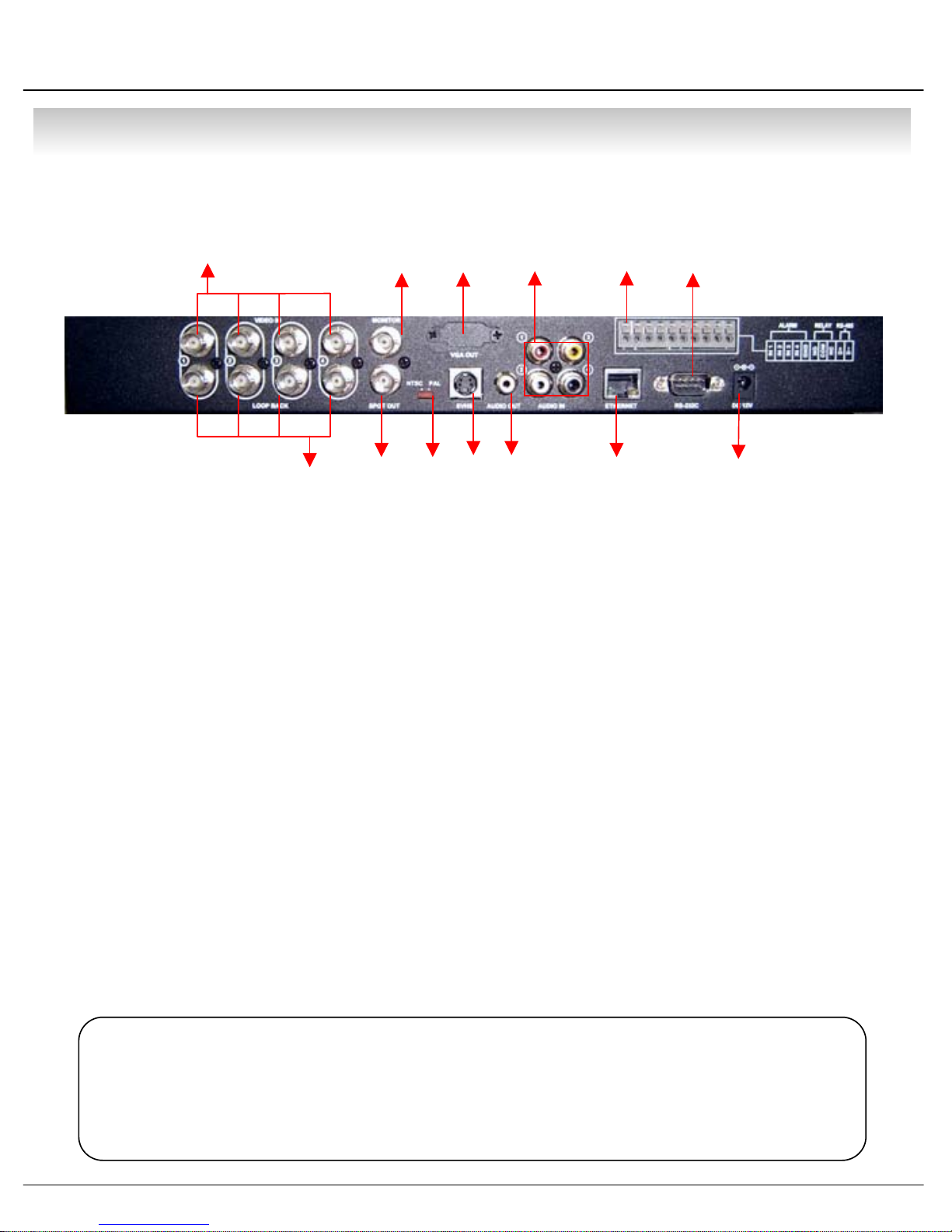
• Description
2. Rear Panel
①
②
① Video In : BNC Port for Connection of DVR & Camera. (4 Camera Connectable)
② Loop Back : Output DVR Camera Video to Loop Back Port. (4 BNC Port)
③ Monitor Out : Output DVR Video to AV Monitor.
④ Spot Out : Output Spot-out Video to AV Monitor.
⑤ NTSC/PAL : Select NTSC or PAL Type.
⑥ VGA OUT : Output Video to a Computer Monitor by Connected VGA.
③
⑥⑨
④⑤
⑦
⑧⑩⑪⑬
⑫
⑦ SVHS : Output Video by Connected SVHS.
⑧ Audio Out : Output Audio Data.
⑨ Audio In : Audio Input Terminal Related with #1~4 Camera.
⑩ Ethernet (TCP/IP) : Port for Cross cable. (Possible to Remote Surveillance.)
⑪ Alarm/Relay/RS-485 : Connect Port for Sensor, Relay, & PTZ.
⑫ RS-232C : Connect Port for Program Debug.
⑬ DC Power Input : Power Supply by DC 12V Adaptor.
Tip
• When System Installation, Please Install under System Power Off Status.
• Please Use Specific Adaptor when Power Supply.
16

• Description
3. Remote Controller
POWER
System
ON/OFF
RETURN
Cancel Setup
or Return to
Previous
MENU: Open Menu
Channel Selection Button
(4ch Available, #1~4 Button)
ENTER: Apply Setup Change
Search Controller : Control Playback Option,
Menu Movement, PTZ/Focus Control
Change
Screen Mode
• Unused Button’s Description is Omitted.
• Every Button is Operated Same as Front Panel Button.
• Remote Controller can Operate when Remote Controller Sensor Input Part Reacted Each Other.
※ If there are many DVR at the same place, they are reacted together when press remote controller.
17
Open
Search Mode
PTZ/IRIS Mode

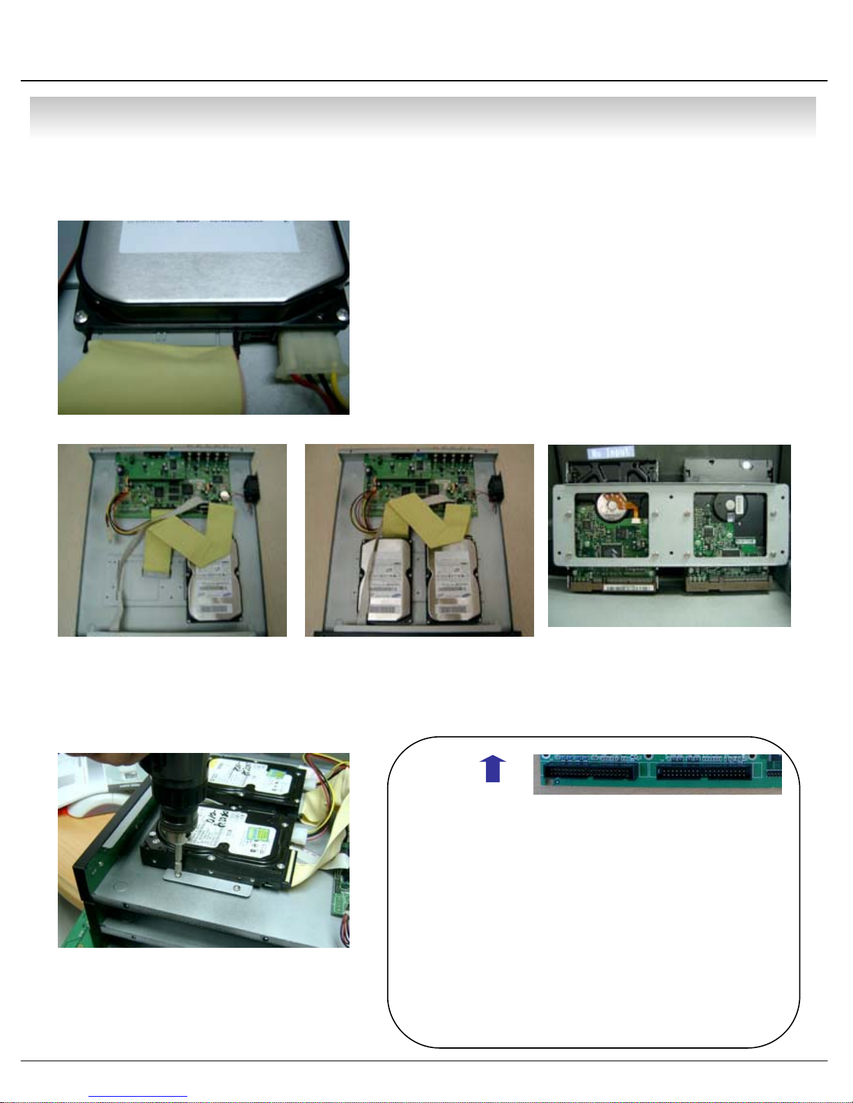
• Installation
1. Hard Disk Installation
① Jumper Setup as Master or Slave
※ Example of Samsung HDD Jumper Setup
• Jumper Setup as master or Slave, Following the
` Direction of Surface of Hard Disk.
• Jumper Located at Hard Disk Data Cable or
1 Rear Side of Hard Disk.
• If One Hard Disk Installation, Setup as Master
If Two Hard Disk Installation, Second One Setup as Slave.
‼ When Hard Disk Add or Exchange, Must System Off
Properly (System Off by Power Button). If not, it’s a
Cause of Fatal Hard Disk Error.‼
② IDE Cable Connection to Main Board
• Refer to General Pin Setting in Jumper Pin Setting on HDD Surface.
• When One HDD Install, Setup Pin as Master and Connect Pin
1 at the Left End of Jumper.
• When Two HDD Install or Additional Install, First One Setup as
1 Master and the Other is for Slave. Slave Setup has No Pin.
• When More than Two HDD install, Setup as Master or Slave
1 to Connect One IDE Cable at the Same Method of Above.
!!Please Use Hard Disk which Possible to Supply Higher than
UDMA66.!!
• Confirm the IDE Cable Inside of Product
• Among the Three Connector, Indicated Blue Color
1 Connector Must be Connected with Main Board. Other
1 Connectors Connected with HDD
18
• Installation
② Connect IDE Cable to Hard Disk
• Insert Disk, Red Cable Head to Power Cable Plug
• Connect Power Cable to Hard Disk in the Same Way
※ If One HDD Install, Connect with End of Connector (Black)
Recommended.
If Add HDD, Connect with Middle Connector (Gray)
Recommended.
One HDD Installation Two HDD Installation Bracket Installation
③ After Finishing Cable Connection, Attach Hard Disk with Screw & Bracket
Tip
For Rear Panel
• When Install Master HDD, Please Connect
1 at IDE1 Port by Master Cable.
• It means, Master Connector which
1 Connected with IDE1 Cable Must
1 Connected with HDD (Master).
ㅡMaster, Slave?
• IDE Hard Disk can connect two equipment at one
cable (port). For the purpose of prevent
confusing, two equipment named ‘Master’ &
‘Slave’. ’Master’ is one hard disk or first hard
disk and ‘Slave’ is below second hard disk.
IDE2 IDE1
19
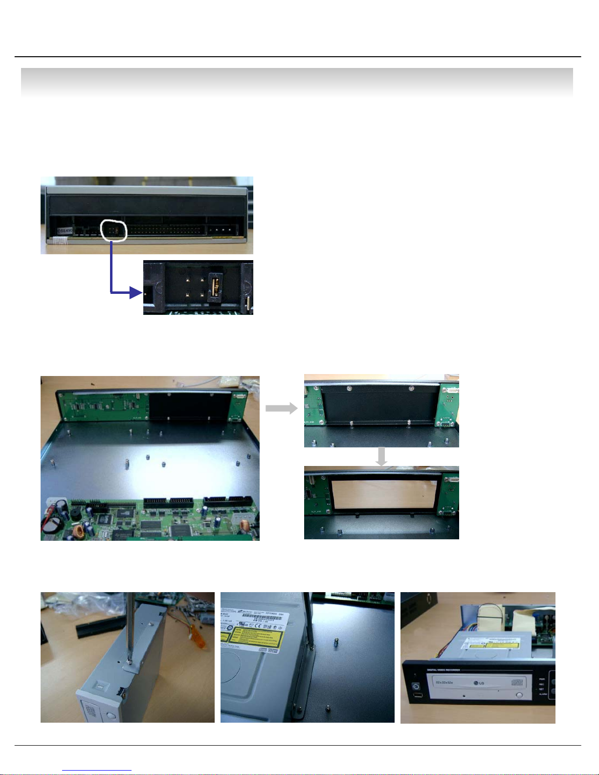
• Installation
1. CD-RW & Hard Disk Installation (SDS-1204B)
① Jumper Setup as Master or Slave
• Jumper Setup as Master or Slave (Refer to CD-RW
1 Direction at the Surface).
• If Install One CD-RW at One IDE Cable, Setup as Master
If Install One CD-RW & HDD at One IDE Cable,
1CD-RW Setup as Slave.
‼ When CD-RW Install, Exchange, or Remove, Please
System Off Properly (System Off by Power Button) and
Disconnect DVR Power.‼
Incase of LG-8526B, MASTER
② Remove Bracket for W/O CD-RW at the Front
③ After Assemble with Bracket, Attach to the Case
20
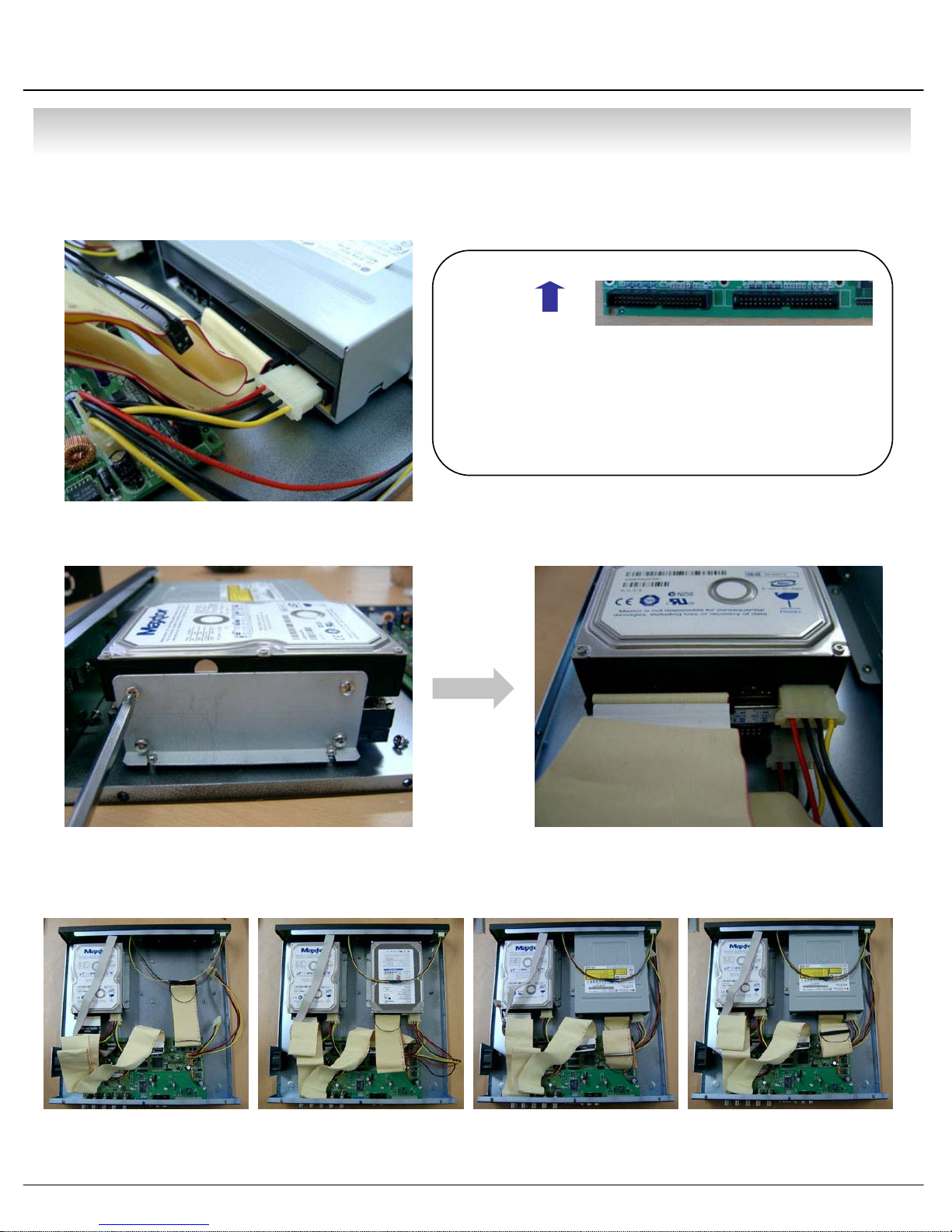
• Installation
④ Connect by IDE Cable & Power Cable at the CD-RW
Tip
For Rear Panel
• When Install Master HDD, Please Connect
1 at IDE1 Port by Master Cable.
• It means, Master Connector which
1 Connected with IDE1 Cable Must
1 Connected with HDD (Master).
⑤ After Assemble with HDD Bracket & Connect Cable (Refer to Previous page for HDD
Setup)
IDE2 IDE1
⑥ Example of Install CD RW & HDD
HDDx1 HDDx3 HDDx1+CD HDDx2+CD
<EX>When Two HDD Installation
21
• Installation
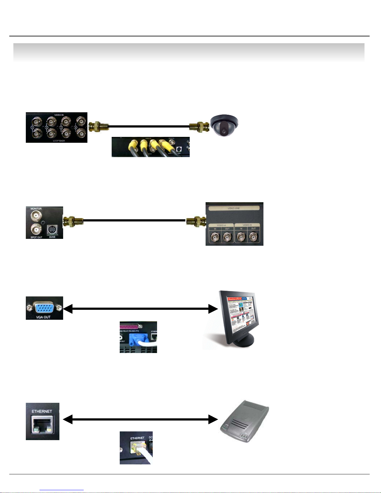
2. Camera Connection
Connect Camera at BNC Port in Back Side Panel.
3. Monitor Connection
Connect Monitor Terminal or S-VHS Terminal to Monitor
4. Computer Connection
Connect VGA OUT Terminal to Computer Monitor
5. Network Connection
Connect Ethernet Terminal and Network Cable
22
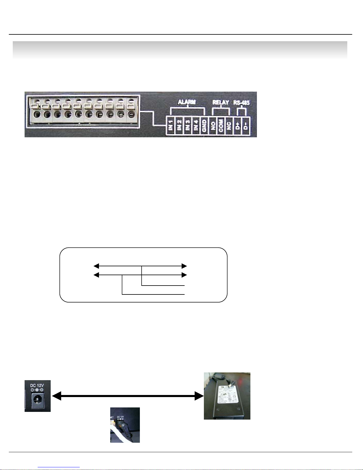
• Installation
6. Alarm/Relay/PTZ Connection
①②
①ALARM
Alarm Input - ‘IN1, IN2, IN3, IN4’ : Connect Sensor Input by Channel
‘GND’ : Connect Ground System
②RELAY
Alarm Output – ‘NO, NC’ : After Checking Alarm Output Type (Normal Open or Normal Close)
and Connect to ‘NO, NC’
‘COM’ : Connect Remain Grounding Conductor
③ RS-485
Connect PTZ Camera – ‘D+, D-’ : Connect PTZ Camera Control Line (+ , – Terminal)
RS485
D+
D-
PTZ 14 Pin Cable
⑨ R+
⑩ R-
③
⑪ T+
⑫ T-
Example of Connection PTZ Camera No. 14 Pin Connector
7. Power Connection
Connect DC Power Input Terminal and Specific Adaptor
23
• Installation
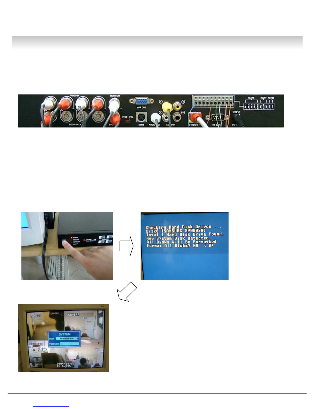
8. Finishing Installation
System Start by Power Button after Finishing Installation
※Hard Disk Format
- If Do Not New Hard Disk Format, System Can’t Recognize the HDD.
So it’s Same Situation of No HDD. Please Format HDD when Insert New HDD.
(Only Display Possible, Not Work Menu & Search)
1. Power On
3. System Start (Initial Mode)
2. New HDD Format
(Select By Play , Backward Play Key)
When new discovery HDDs are two, It ask about each
format. Then choose the Yes about all HDDs. If you
Format the first HDD only, maybe second HDD don’t
Format.
※ When you are doing to format, Never turn off.
If tuen off, HDD is able to occur fatal error.
24

• Display
1. System Power ON
• Press Power Button to Start System
• After Checking Hard Disk, Need input Password to
1 Operation
• Initial Screen View Mode is Quad Division Mode
1 and Recording Mode
CAMERA
2004/01/01
00:00:00
Picture for Power On
after Finishing Installation
Tip
• Check System Condition at LED
POWER : Showing System On/Off
RECORD : Showing Record On/Off
NETWORK : Showing Client Connection Status
ALARM : Lighting when Sensor Alarm Activate
2. Select Screen Mode
• Select One Channel among 4 Channels
CHANNEL
• Move to One Enlargement Watch Mode when Quad Screen Division Mode
• Each Channel Indicate Camera Name & Recording Status
• Present Time & Date Indicate at Monitor Central Lower Side
• Move to One Enlargement Watch Mode when Rotation Mode
25

• Display
3. Screen Rotation Mode (SCR MODE)
• User can Select 3 Kinds Watch Mode
SCR MODE
Quad (4CH) Division
Watch Mode
① Quad (4CH) Division Watch Mode
②Selected 1CH Watch Mode
③ 4CH Rotation Watch Mode
• Quad (4CH) Watch Mode is Initial Mode when System Start
Selected 1CH
Watch Mode
4CH Rotation Mode
4. PTZ/FOCUS Control
• Control Camera PTZ (Pan/Tilt/Zoom) & Focus (Only Useable for Proper Camera)
PTZ/FOCUS
• Press PTZ/FOCUS Button to Open PTZ Menu at Right-Under Side and Control by
1 Search Controller
• Press PTZ/FOCUS Button Second Time to Open FOCUS/IRIS, PRESET, SWING
Menu and Control by Search Controller
26

• Display
PTZ CTL
UP
LEFT RIGHT
DOWN
FOCUS/IRISCTL
UP
LEFT RIGHT
DOWN
PRESET
NUMBER:1
NUMBER CHANGE:UP/DOWN
SET:F1 GOTO:F2
SWING
MODE:PAN SWING
NUMBER CHANGE:UP/DOWN
FIELD CHANGE:LEFT/RIGHT
SET:F1 RUN:F2
Fast
Backward
Backward
Play
Search Controller
Play
Fast
Forward
4.1 PTZ Control
① Control Camera Movement by ‘Faster’, ‘Slower’, ‘Backward Play’, ‘Play’ Button (Up,Down.Left,Right).
② Zoom In & Out by ‘Fast Backward’, ‘Fast Forward’ Button.
③ Keep Press Button Make Continuous Movement.
4.2 FOCUS/IRIS Control
① Control Iris by ‘Faster’, ‘Slower’ Button.
② Focus On by ‘Backward Play’, ‘Play’ Button.
③ Zoom In & Out by ‘Fast Backward’, ‘Fast Forward’ Button.
④ Keep Press Button Make Continuous Movement.
27

• Display
4.3 PRESET Control
PRESET
NUMBER:1
NUMBER CHANGE:UP/DOWN
SET:F1 GOTO:F2
④ Save by Front Panel Key No.1 Button or F1 Button on Remote Controller.
⑤ To Move to Saved Location, Press Front Panel Key Button No.2 or F2 Button on Remote Controller.
⑥ It support at Protocol D/Protocol P/D-MAX only.
※ In protocol D case, It have to keep the memory after memorable setting are deleted.
① By Preset Function, Possible to Setup Direction and Focus of PTZ Camera.
② After Selecting Position at PTZ Control Mode, Save Data at Preset Mode.
③ Setup ‘NUMBER’ from 1 to 128 by ‘Faster’ & ‘Slower’ Button.
4.4 SWING Control
① SWING Function Dedicate Each No. of Saved Preset and Swing as Pan or
SWING
MODE:PAN SWING
NUMBER CHANGE:UP/DOWN
FIELD CHANGE:LEFT/RIGHT
SET:F1 RUN:F2
③ PAN SWING MODE : Rotate Left , Right Side.
TILT SWING MODE : Rotate Up, Down Side.
START PRESET : Select Starting Point. (1~128)
END PRESET : Select End Point. (1~128)
SWING TIME : Select Halt Time as Each Point. (1~64sec)
SWING SPEED : Select Moving Speed of Camera. (1~64)
Tilt.
② Changing Mode by Backward Play Button.
Changing Setup by Faster, Slower Button.
④ Save by Front Panel Key No. 1 Button or F1 Button on Remote Controller.
⑤ For Start SWING Mode, Press Front Panel Key No.2 or F2 Button on Remote Controller.
⑥ It support at D-MAX only.
Tip
• All ability work by camera is supported each protocol.
28

• Display
5. System Power OFF
Tip
• System Log-On Possible ID : ‘Administrator’, ‘Manager’, ‘Operator’
Administrator: All Function Access (System On, Shutdown, Setup, Search)
Manager: System On and Search
Operator: System On
• Press Power Button to System Off
• Input Password and Press Enter to Shutdown System
29

• SEARCH
⊙ Go to Search Mode
SEARCH
• Press Search Button and Log-In
Administrator or Manager
• Use Direction Key to Move Menu
Search Recorded Data
1. Search by Date/Time
- Possible to Search Recorded Date & Time
ENTER
RETURN
① Move Cursor to Selected Date in Calendar
(Recorded Date & Time Indicated by Gray Color)
② Press Enter to Open Selected Date
③ Recorded Time Appear to Under Side
④ Press Enter at Selected Time
(One Scale is 15 Minutes)
⑤ Menu Disappear and Output Recorded Video
• Return to Previous.
(Move to Previous Menu or Exit Search
1 Mode and Return to Watch Mode)
• To Open Each Menu Press Enter
1 or Press Play Button
• Showing Recorded Date & Time at Left-Upper Side
1 as Watch Mode.
1 Showing Playing Condition at Right-Under Side.
• Channel Selection Button in Watch Mode & SCR Mode
1 Button are Apply the Same as Search Mode.
(But Menu, Search, and PTZ/Focus Buttons are Exception)
30
2004/01/01
00:00:00
>

• SEARCH
• Control Playing Video
① : Basic Playing Mode (Normal Speed (1X) Forward Playing)
② : Normal Speed Backward Playing
③ : Pause Video
④ : Fast Forward (2 ~ 64 Speed)
⑤ : Fast Backward (2 ~ 64 Speed)
⑥ : Same Function as # ④,⑤
※ Press Normal Forward/Backward Button in Pause, Move to Next/Previous Frame.
2. Search by Event
- Searching Video with Event Occurrence to Set up Period
Set up Period to Select Start Date & Finish Date
for Searching Event
Alarm : Searching Alarm Event during the Selected
1 Period
Motion : Searching Motion Detected Event during
1 the Selected period .
Timer : Searching Schedule Change or Recording
1 Setup Change Event
System : Searching Power On/Off Event (etc.)
1 Concerned System Event
Event List Showing at Below Output Window
Tip
• Alarm, Motion, System can be Select plural by Check (V)-(ENTER)
• To Change Setup, Press Enter and Press Direction Key
After Changing Setup, Press Enter to Exit.
31
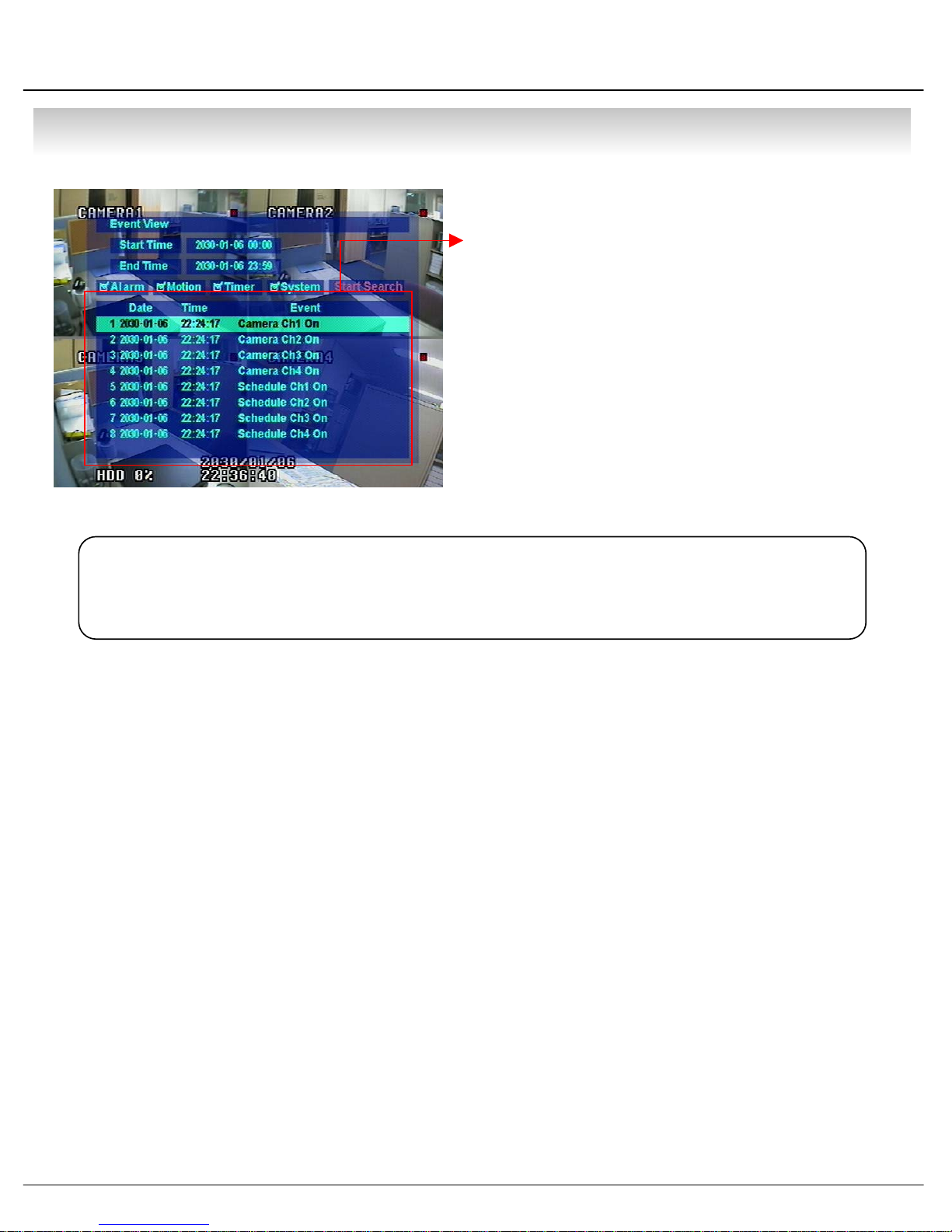
• SEARCH
• Date : Indicate Event Occurrence Order & Date
Time : Indicate Event Occurrence Time
Event : Indicate Event Contents & Camera No.
• Event Searching Method
① User can Search Event Using by Direction key
② Search Event to Press Enter at Selected Event
from Event Occurrence Time
③ Control Video is the same way as Time Mode Control
Tip
• The Search by Event is not Base on Video, but Event Occurrence Time.
32
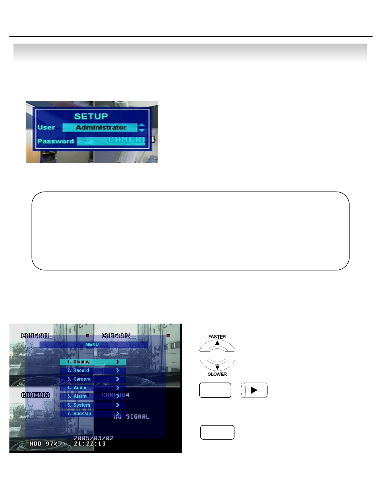
• MENU
⊙Go to Menu
① Press Menu Button on Front Panel in Watch Mode
② Ask Password
③ Input Password Using by Channel Select Button
1 [1][2][3][4])
④ After Input Password Press Enter to See Menu
Tip
⊙Menu Initial
• Initial Administrator, Manager, Operator Password is 1234.
• Showing Password as *
• Changing Password (MENU->6.System->4.Password )
• Only Watch Mode can go to Menu.
(Search & PTZ/Focus Mode can’t move to Menu)
• Every System Setup can Change or Maintain
1 at Menu (6 Setup)
•
Move to Menu Using by Up
& Down Button
•
ENTER
To Open Detail Menu or to Apply Input
•
RETURN
Return to Previous Menu or Return to Watch Mode
33

• MENU
1.Display
- Video Setup for Watch Mode
1. Date/Time : Date & Time Mark On/Off
2. Title : Camera Name On/Off
3. Status : Record Condition Mark On/Off
(Recording: Red, Pre-recording : Green)
4. Border : Border Mark On/Off
when 4CH Division Watch Mode
5. Border Color : Select Border Color
(White, Blue, Red, Yellow, Green, Gray)
6. Sequence Dwell : Setup Rotation Cycle Time
(1~60 Sec.) when 4CH Rotation Mode at Watch Mode
7. Spot-Out Dwell : Setup Spot-Out Time Cycle
(1~60 Sec.) to Transmit Video
8. Deinterlace Mode : Remove Screen Spread on High
Resolution , Low Frame
※Only Applying When D1(704X480)
2.Record
- Setup Image Record
2.1 Size/Rec.Rate/Quality – Setup Recording Resolution, Compression Rate, Quality
-Camera : Indicate Camera No. to Setup
-Size : Setup Resolution
-Rec.Rate : Setup Compression Rate
-Quality : Setup Quality of Recording Video
34
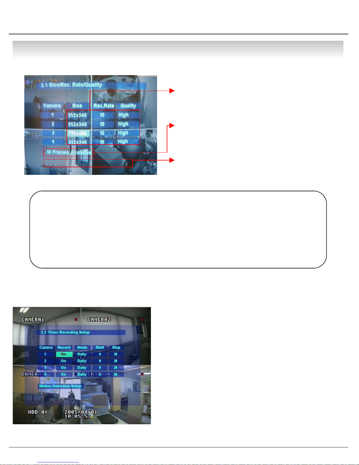
• MENU
• Size : 352*240, 704*240, 704*480
Rec.Rate : Possible to Select (1~30)
Quality : Possible to Select 3 levels (High, Low, Standard)
• Indicate Frame No. to Control Size & Rec. Rate
Overlimit Recording Capacity
Tip
• When Setup Refer to Below NTSC, PAL Type
NTSC : 352*240(120fps), 704*240(60fps), 704*480(30fps)
PAL : 352*288(100fps), 704*288(50fps), 704*576(25fps)
• Possible to Setup Size & Rec. Rate, Quality per Each Channel
• When Applying Change Setup, Press Enter,
1 When Cancel Change Setup, Press Return.
• If Frame Over, Showing a Message ‘Overlimit Recording
1 Capacity’ and Impossible to Change Size & Rec. Rate
2.2 Timer Recording Setup – Record On/Off or Time, Motion Setup
• Camera : Indicate Camera No. to Setup
• Record : Record On/Off
• Start : Setup Recording Start Time (0~24 hr)
• Stop : Setup Recording Finish Time (0~24 hr)
* Recording Time is between Start Time and Finish Time.
• Motion : Motion Detection Recording On/Off
(Record Setup must be ‘On’, when Motion Detection
1 Recording.)
35
• MENU
g
g
p
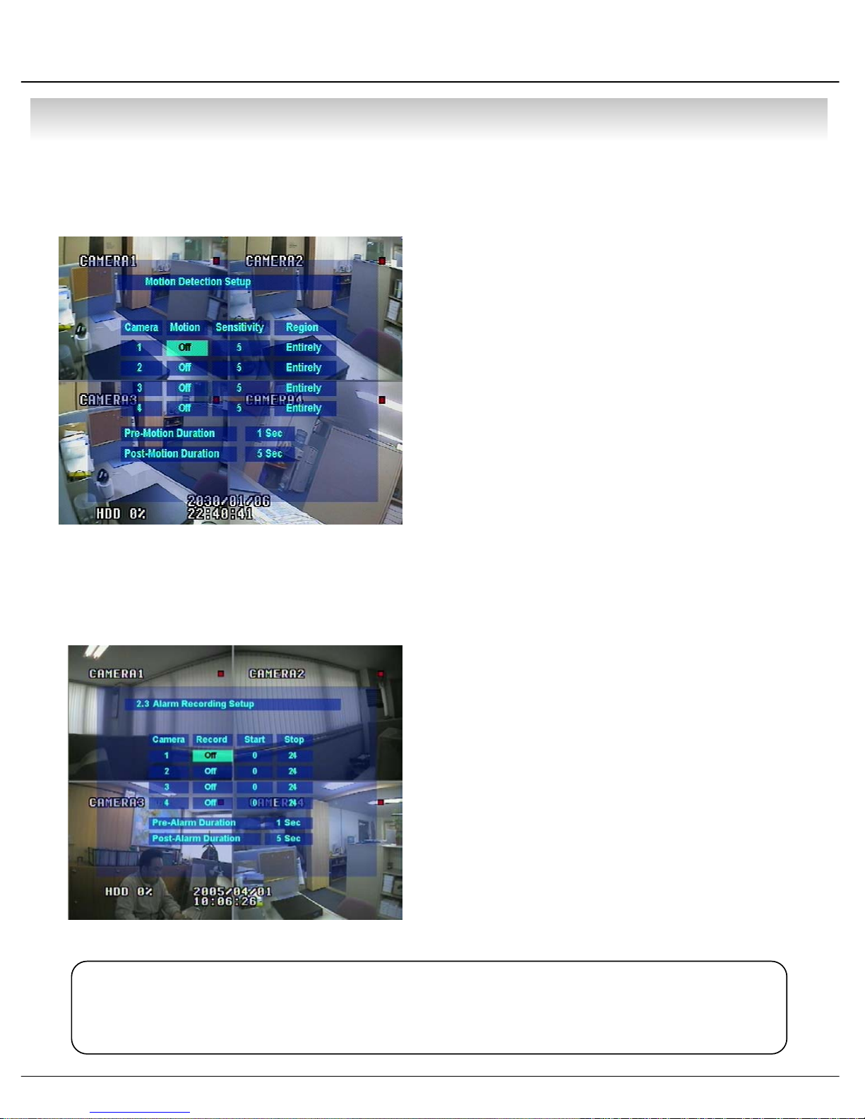
2.3 Motion Detection Setup – Motion Detection Area & Sensitivity
• Camera : Indicate Camera No. to Setup
• Sensitivity : Control Sensitivity (1~100)
• Region : Setup Motion Detect Range
Entirely – Setup Entire Screen
Partially – Setup Partial Screen
• When Choose Region as Partially, Move to Partial
1 Range Setup. Press Enter After Partial Ran
1 to Finish Region Setup.
• Pre-Motion Duration : Setup Pre-Motion Duration Time.
1 (1~5 sec)
• Post-Motion Duration : Setup Motion Detect Recording
1 Time after Motion Detected (5sec~3min)
Large No. is More Sensitive.
e Setup
2.4 Alarm Recording Setup – Recording Setup for Alarm Activated
• Camera : Indicate Camera No. to Setup
• Record : Setup Record On/Off when Alarm Activated
• Start : Setup Alarm Recording Start Time (0~24 hr)
• Stop : Setup Alarm Recording Finish Time (0~24 hr)
• Pre-Alarm Duration : When Alarm Recordin
1 Start Recording Time before Alarm Activate (1~5sec)
• Post-Alarm Duration : Setu
1 after Alarm Activate (5sec~3min)
Tip
• Motion Setup Work by Time Schedule and Alarm Schedule Work Independently.
, Setup
Alarm Recording Time
36
• MENU
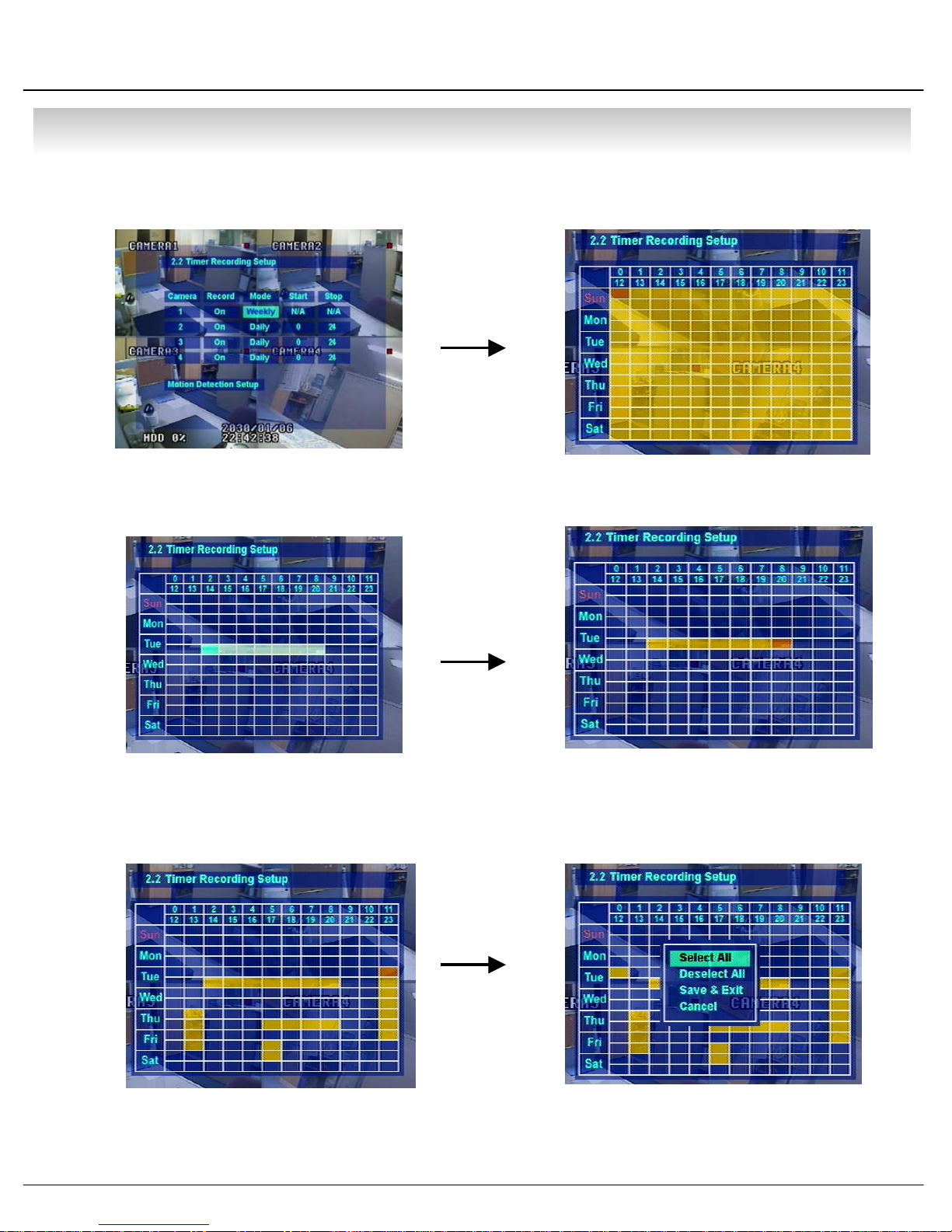
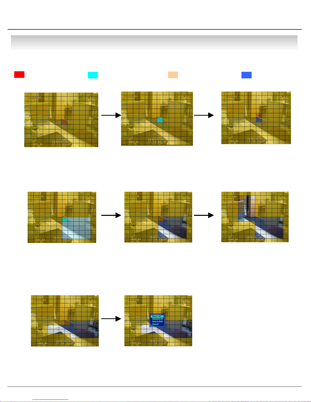
⊙ Time Recording Weekly Setup
①②
Weekly mode Setup at Record Setup Scheduled Region Indicated Yellow
③④
After ‘Deselect’ Schedule, Activated Region by
Press ‘ENTER’ and Select Date & Time to Move
Cursor
⑤⑥
Setup Date & Time Schedule in the Same Way.
After Finishing Schedule Setup,
Press ‘Return’ for Save & Exit
After Selecting Region and Press ‘ENTER’ Again
to Finish Schedule Setup (Red)
• Select All : Entire Region Select
• Deselect All : Cancel Region
• Save&Exit : Save Changing Setup & Exit
• Cancel : Cancel Changing Setup & Exit
37
• MENU
⊙ Partial Motion Region Setup
:Non-Activate Move Cursor :Activate Partial Setup Cursor :Partial Setup Finish Cursor :Non-Activated Region
①②
Region Initial View
④
Move Cursor by Direction Key and
Press Enter at Selected Region
⑤
③
Press Enter again to see
Region as a Blue Color and
Setup Non-Activate Region
⑥
When Select Multi Region,
Using Direction Key in ② to
Expand Non-Activate Region
⑦
For Reducing Partial Region,
Cancel Non-Activate Region
in Same Way as ④⑤
Press Enter to Select Multi
Non-Activate Region
⑧
When Finishing Partial
Region Setup, Press Enter
to Save & Exit
38
Same Method as ④⑤, Possible
to Expand Non-Activated
Region
• Select All : Select Entire Region
• Deselect All : Cancel Region Setup
• Save&Exit : Save the Changes & Exit
• Cancel : Cancel Change Setup & Exit

• MENU
3.Camera
-Setup Camera
3.1 Status/Title Setup – Camera Connection Status & Camera Name Setup
• Camera : Indicate Camera No. to Setup
• Status : Indicate Camera Status
(Connected/Disconnected)
• Title : Setup Camera Name to Show Left-Upper Side
Tip
•Title Input Method
Using Direction Key, Up & Down Keys for Alphabet A~Z, Numerical No. 0~9
1 Left-Right Keys for Move to another Letter.
3.2 Covert/PTZ Setup
• Camera : Indicate Camera No. to Setup
• Covert : Setup Covert On/Off
*What’s Covert?
When Covert On Watch Mode, Display Video is 1
1 Hidden, but Recording is On.
• PTZ Address : Select PTZ Camera Address
• PTZ Protocol : Select Kind of PTZ Camera
• Baud Rate : Setup PTZ Communication Speed
(2400, 4800, 9600 BPS)
※PTZ Supplied Protocol :
Samsung(MRX-1000), Samsung(SCC641),Honeywell(SD1)
Honeywell((GMC),Lilin(Fastdome), Fastrax(Ⅱ), GC(655H),
D-MAX, Sunin DSC-230, Scan Dome-Ⅱ, Vicon,
Sensormatic,Panasonic(WV-CS850), Panasonic(WV-CSR604),
Kalatel(KTD-312), PELCO-D, PELCO-P,Dynacolor
39
• MENU
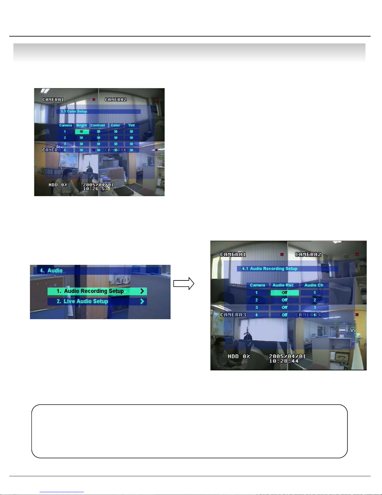
3.3 Color Setup – Control Video Color
4.Audio
- Setup Audio
• Camera : Indicate Camera No. to Setup
• Bright : Control Monitor Bright
• Contrast : Control Monitor Contrast
• Color : Control Monitor Color
• Tint : Control Monitor Tint
* All Setup Possible to Control 0~100
4.1 Audio Recording Setup – Audio In Setup
• Camera : Indicate Camera No. for Setup
• Audio Rec. : Setup Recording On/Off from External
1 Audio In Terminal
• Audio Ch. : Setup Audio In Terminal Channel &
1 Audio Output Camera
Tip
• User can Listen Saved Audio with Saved Video
• Audio Check in Search is Possible Only Normal Speed (1X) Forward
1 Playing at 1CH Mode (Audio Recorded Channel)
40

• MENU
4.2 Live Audio Setup – Audio Out Setup
• Live Audio : Audio Output ON/OFF
• Monitoring Ch. : Select Channel for Audio Output
1 Nr. 1~4 Audio In
• Network Audio
① Enter ‘4.Audio -> 4.2 Live Audio Setup’ at the Menu.
② Select ‘One-way’ or ‘Two-way’ at the Network Audio.
③ One Way : Transfer Audio from DVR to Remote Client.
Remote Client Possible to Receive Audio with Video.
④ Two Way : Communicate Audio between DVR and Remote Client.
Remote Client Possible to Receive & Send Audio to DVR Server.
Live Audio Output from Audio In Terminal
⑤ Network Audio Possible to Operate even Live Audio Off.
5.Alarm
- Setup Alarm & Relay
5.1 Alarm Input Setup – Alarm Sensor Setup
• Alarm : Indicate Alarm Input Terminal No.
• Status : Setup Alarm Sensor Connection Status
(Connected/Disconnected)
Tip
• Generally Alarm Sensor can be Divided Two Types.
Normal Open Type is Open Sensor Electrically and Reacted when
1 Signal is Connected.
Normal Close Type is Close Sensor Electrically and Reacted when
1 Signal is Disconnected.
• Camera : Input Camera No.1~4 to Connect Alarm
• Type : Setup Alarm Sensor N/Open, N/Close Type
41

• MENU
5.2 Relay Output Setup – Alarm Relay Setup
• Alarm : Indicate Alarm Input Terminal No.
• Relay Out : Setup Relay Connect with Alarm Sensor
• Mode : Setup Reacted Relay as Latched/Transparent Mode
• Duration : Setup Reacted Relay Time
1 (5sec~5min or Until key-in)
• Relay Type : Setup Relay Type N/Open or N/Close
Tip
•Latched/Transparent
Latched – When Sensor Alarm Activated, Relay Reacted in Setup Duration
Transparent – Relay Reacted Temporary During Sensor Alarm Activate
6.System
- Basic Environment Setup
6.1 Date/Time – Date & Time Setup
• Date : Setup Present Date (YYYY-MM-DD).
(If Time Setup to Past Date, Ask Delete Data for the Past Date.
NO->Date/Time No Change, YES->After Delete Past Data and Change Date/Time )
• Date Format : Select Date Output Type (Ex: 2004-00-00, 2004/00/00)
• Time : Setup Present Time
• Time Format : Setup Time Type as 12 Hour Base or 24 Hour Base
42

• MENU
• Daylight Saving : Summer Time Applying Status
Apply the daylight
saving
It means that it apply the daylight
saving (summer time) in Korean.
Please, apply the daylight saving at the PC setting.
- Never change the real time. Only apply the daylight saving “ON”
Please apply the daylight saving at the DVR and PC certainly.
If not apply the daylight saving at the PC, The daylight saving is not applied at the RemoteAgent.
43

• MENU
6.2 Network – Setup TCP/IP
• IP Address : Input IP Address
• Gateway : Input Gateway IP for Internet Server
• Subnet Mask : Input Subnet Mask IP
• Network Speed : Setup Network Speed
(Network Speed from System, Depend on Network Status)
※ If Change Network Setup, New Change Apply
when after Rebooting.
• Press the NEXT button and progress the step.
•Don’t change the DDNS name because it is fixed the domain name.
<DHCP ON, DDNS OFF> <DHCP ON, DDNS ON>
<DHCP OFF, DDNS OFF> <DHCP OFF, DDNS ON>
※ If your network connect at the router, please must work the port forwarding. Otherwise you can't
receive the service well.
When you connect by the web ,please 80 port must be work port forwarding for DVR.
When you connect by the RemoteAgent Program ,please 6100 port(User can change it) must be
work port forwarding for DVR.
If you want to know more, please ask to the network manager or refer the router manual.
44

• MENU
DHCP
① Enter to ‘6.System -> 6.2 Network’ on the Menu.
② Setup DHCP On/Off.
③ DHCP Off : User Input IP Address by Himself.
④ DHCP On : After DHCP On, Reboot the System.
⑤ Can see the setup IP automatically at the system information.
※ DHCP (Dynamic Host Configuration Protocol) : Indicate IP Address for the DVR
Automatically.
DDNS
DDNS(Dynamic DNS): You can connect the DVR by the fixed domain
name(ex.00115f000001.dvrlink.net) at client or Web without entering the IP address.
1. Enter to ‘6.System -> 6.2 Network' on the menu.
2. Setup DHCP On or Enter the IP address.
3. Setup DDNS ON and reboot.
4. Enter to ‘6.System -> 6.6 System information’on the menu.
5. Confirm the MAC address.
6. The domain name is "MAC address.dvrlink.net".
EX) If Mac Address is 00-11-5f-00-b5-a7, the domain name is "00115f00b5a7.dvrlink.net"
7. If you connect by "00115f00b5a7.dvrlink.net" at client program or Web, you can connect the DVR.
※ 1. If your network connect at the router, please must port forwarding.
2. Please, you must enter the exact IP address, DNS Server, Gateway, Subnet Mask.
3. Please you must connect the DVR at External Network.
If you don't follow 1,2,3 , you can't receive the DDNS service.
※ If you use the DDNS, there is no
necessity to enter again the IP Address
every connection..
Possible to Confirm IP Address for the
DVR at the System Information.
Fixed MAC address of the DVR
45

• MENU
Webserver Port Change
Support the Webserver port’s change by manually.
Basic port: 80
If you change the port, please write the port number after writing the address at the web.
Ex) If you change the port number by 8080, you have to connect as below.
http://192.168.0.40:8080
6.3 Buzzer Setup – Setup Key Sound to Speaker
• Alarm Input : Alarm On/Off when Alarm Activate
• Videoloss : Alarm On/Off when Camera Disconnected
• Disk Full : Alarm On/Off when Hard Disk Full
• Disk Error : Alarm On when Hard Disk Error
• Key Input : Setup Key Input Sound
6.4 Password – Setup Password
6.4.1 Administrator Password – Setup Menu & System On/Off
• Current Password : Input Current Password (Initial Password : 1234)
• New Password : Input New Password
• Re-enter the Password : Re-Confirm New Password
• Save&Exit : Applying New Password
46

• MENU
6.4.2 Manager Password – Possible System On & Search, But Can’t Change Setup
6.4.3 Operator Password – Possible System On, But Can’t Change Setup and Search
• Current Password : Input Current Password
(Initial Password : 1234)
• New Password : Input New Password
• Re-enter the Password : Re-Confirm New Password
• Save&Exit : Applying New Password
• Current Password : Input Current Password
(Initial Password : 1234)
• New Password : Input New Password
• Re-enter the Password : Re-Confirm New Password
• Save&Exit : Applying New Password
47

• MENU
6.5 Disk Write Mode – Setup Hard Disk
• Disk Overwrite : Select Overwrite Permission when
1 Hard Disk Full
O N: Overwrite Hard Disk from Oldest Data
OFF: When Hard Disk Full, Stop Recording and
1 Buzzer Activate (Refer to Menu 6.3 Buzzer Setup)
• Disk Initialize Now : Refreshment Hard Disk
All Recorded Data Deleted
• When Select Disk Initialize, Alarm Message Showing.
1 Select ‘Yes’ to Start Disk Initialize.
※When Change Disk Overwrite ON/OFF Mode, the Change will be Applied from Changing Time.
For Example When Overwrite On Mode & HDD Full, Change to Overwrite Off Mode and then it will be Applied New Data
Fill HDD Full after Changing Time.
6.6 System Information – Product information (Version etc)
6.7 Factory Default – Every Setup Initializing
• S/W Version : Indicate S/W Version of the Product
• H/W Version : Indicate H/W Version of the Product
• Video Signal Type : Indicate Video Signal Type
• Disk Size : Indicate Hard Disk Capacity
• Number of HDD : Indicate Present Installed HDD No.
• IP Address
• MAC Address
• Press Enter to Start Initialize
• Showing Warning Message and Press OK to Run Initialize
• If do Factory Default, Every Setup is Initialized, but
1 Saving Image is Not Erase.
48
• MENU
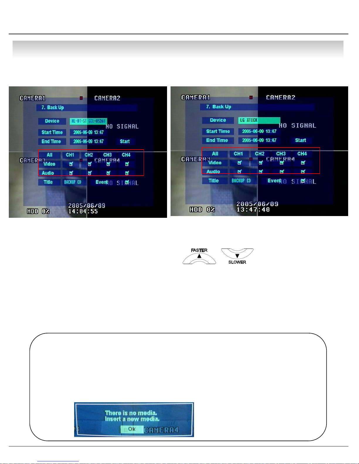
7. CD and USB Backup
①
②
③⑦
④
⑤⑥
① Device : Indicate CD-RW Model and USB MEMORY Model Automatically.
If you use the CD-RW and USB memory (or USB HDD) together,
it can choose the CD-RW and USB by Button.
② Start Time : Select Start Backup Time.
③ End Time : Select End Backup Time.
④ Channel & Video/Audio Selection : Select Channel, Video, & Audio for Backup.
①
②
③⑦
④
⑤
⑥
⑤ Title : Change the Title of Backup.
⑥ Event : Select Attach Event Text File in Backup.
⑦ Start : Start Backup.
Tip
• Compatible CD Writer Models are LG(GCE-8526B,GCE-8527B),
SAMSUNG(SW-252F, TS-H292A),ASUS(CRW-5232AS),GIGABYTE(GO-R5232B)
• Compatible USB memory stick Models are LG(Royal,mobile,mirror),IMATION(iflash) and
Compatible USB HDD is CUTIE(FHD-254).
• Inside of Backup CD,USB Including Necessary Codec for Playback (IMM4 Install File).
• In case of RW Possible CD, Please Delete Previous Data on PC for Recording Again.
• In Case of Non-Proper CD or
1 Undeleted RW-CD, Error Message
1 will be Appeared.
49
• MENU
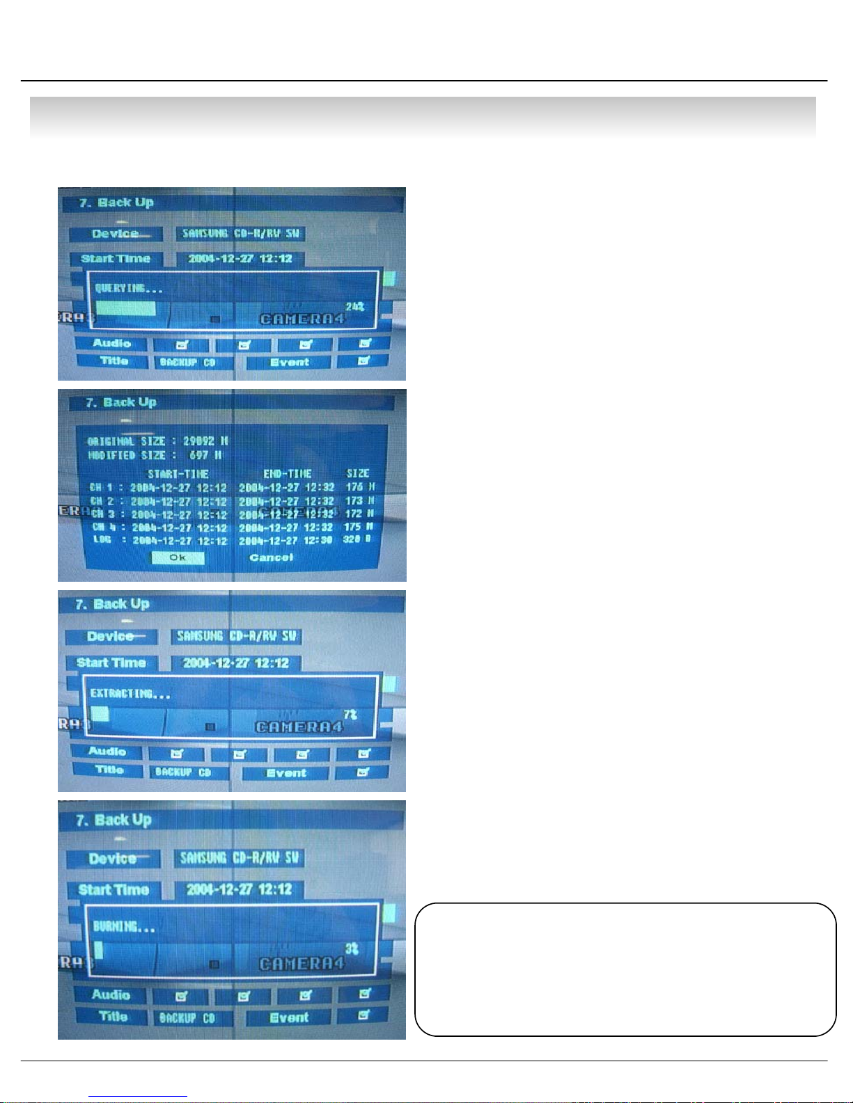
7.1 CD Backup Process
1. Choose the CD-RW at the DEVICE.
2. Choose the start time and end time.
3. Choose the each channel Video/Audio. If you want
the Event BACK UP, Choose the event.
4. Choose the BACK UP title .(Default: “BACKUP CD”)
5. Backup by Start button.
6. By User Selection Backup Time Calculation, the
Capacity of CD will be Arranged.
7. Extract Data for CD Backup.
8. Create the AVI format at the data in store.
9. Burning CD.
Tip
• During CD Burning, Other Function can
NOT Operated.
• During CD Burning, Record Data &
Remote Client Connection are Possible.
50
• CLIENT
• System Requirement
① Main Board (CPU): Celeron700(Minimum), Pentium 4 recommend
② OS: Higher than Windows 98,DirectX 7.0A
③ Memory (RAM): More than 128 M
④ VGA: Overlay YV12 Format Graphic Card
All Radeon, Nvidia (Higher than Geforce) Matrox (Higher than G450) Compatible Video Card
※IMM4 Codec (When Playback Backup File)
• DVR Remote Agent Install
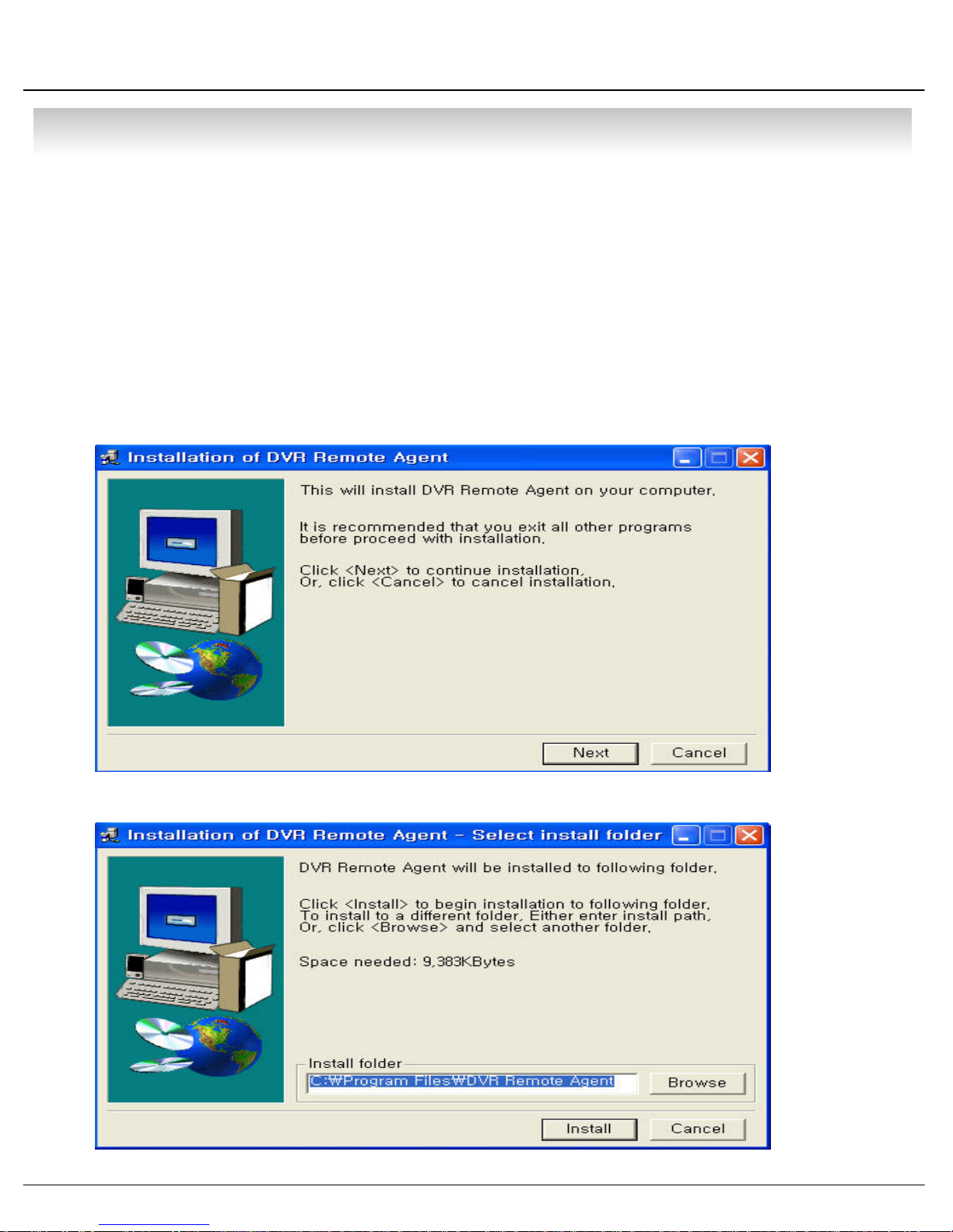
① Open CD-ROM Drive and Run DvrRemoteAgentSetup.exe and then Appear Setup Menu
② Close All Running Software and Press Next to Move Next Step
51
• CLIENT
③ Ask designate Folder to Install DvrRemoteAgent,
Recommend Basic setup c:₩program files:₩DvrRemote Agent.
Click Next.
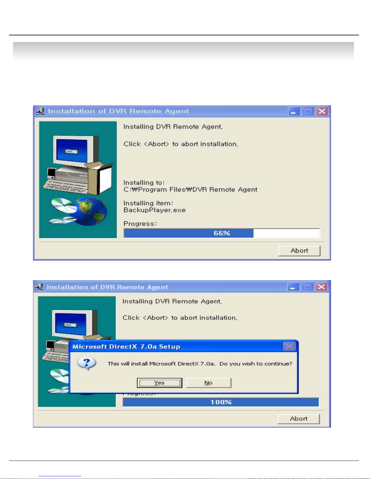
④ Showing Progress of Copy of Files
⑤ Appear DirectX 7.0a Install Menu. If DirectX Version Lower than 7.0a, Press Yes to Start Install
52
• CLIENT
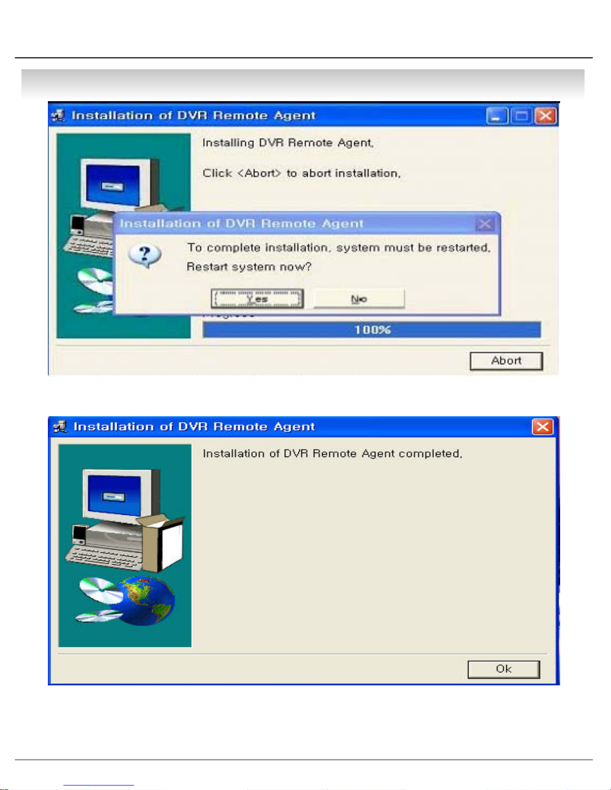
⑥ When Finishing Installation, System must be Restarted. Click ‘Yes’
⑦ Finish DvrRemoteAgent Program Installation
53
• CLIENT
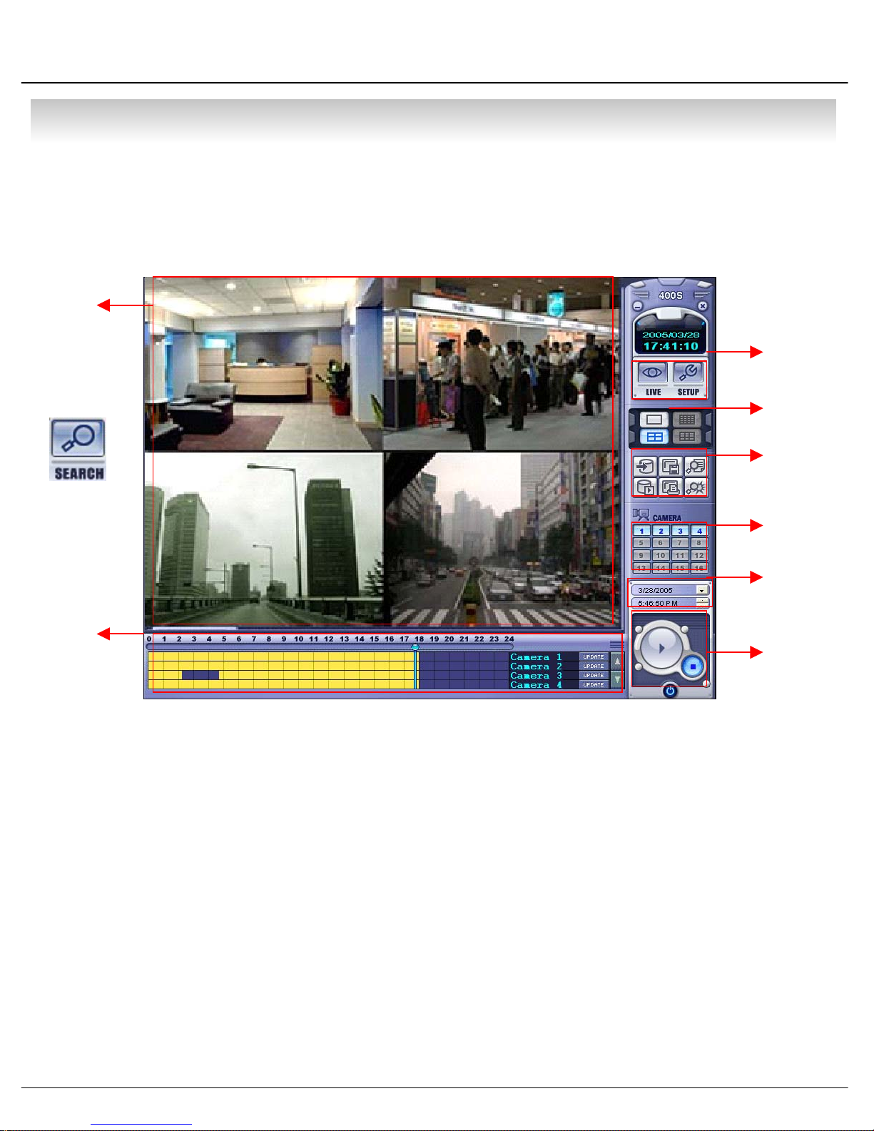
1. Monitoring Mode
1.1 Function Introduction
①
③
④
⑤
⑥
⑦
⑧
⑨
⑩
⑪
②
⑫
⑬
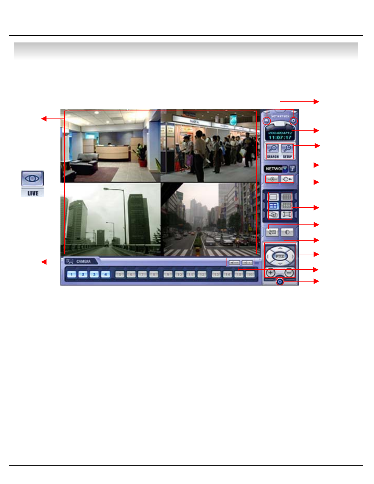
① Main Screen Image : Showing Present Surveillance Camera Image
② Camera Selection Button : Indicate Connected Camera No. & Select Image to Click Camera No.
③ Hidden/Exit : Hide DVR Client Window or Exit Program
④ Time Output : Showing Present Time & Date
⑤ SEARCH : Move to Search Mode to Play Video
SETUP : Move to Setup to Change Network Setup or Option
⑥ DVR Selection : Select I/D to Connect Server
⑦ Connect : Connect DVR
Disconnect : Disconnect from DVR
⑧ Screen Division Selection : Change Screen Division Mode
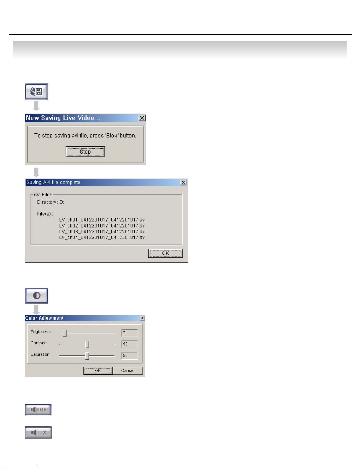
⑨ Save by AVI file : Transmission Live Image Save by AVI File
⑩ Color Adjustment : Adjust Color of Live Transmission Image
⑪ PTZ Control Button : Control Camera PTZ & Focus
⑫ Audio Button : Control Two Way Audio & Mute
⑬ Exit : Exit DVR Client
54

• CLIENT
1.2 Screen Division Selection
1.3 P/T/Z Control
• 1*1 View : Showing One (1) Video which User Selected
(Selection Video by Camera Selection Button)
• 4*4 View : Quad Screen Division Mode
• Screen auto switching : One Large Screen Mode Showing One by One (1*1
View) Depend on User Selection Time (Not Work Screen
Division Mode)
• Full Screen View : Present Video Move to Full Screen Mode
Mouse Double Click when Return Previous
*Mouse Double Click Make the Same Function as Full Screen.
• P/T/Z Controller : Camera P/T/Z Control by Direction Keys
• FOCUS/ZOOM Select Button : Focus or Zoom Control by +,- Button
• +,- Control Button : Focus or Zoom Control
1.4 Selection Network I/D
Network Information Icon
• Select I/D to Connect Server.
• I/D can be Add, Change, and Delete at Setup
• Click Network Information Icon, to See a
1 Popup Window for Connected Server I/D,
1 IP, and Port Information.
55
• CLIENT
1.5 AVI File Conversion
• Click AVI Conversion Button to Start AVI File Conversion.
• During AVI Conversion Showing a Message and before
1 Click ‘Stop” Save AVI File continuously .
• ‘Press ‘Stop’ to Open Designate File Name
1 & Saving Location, and Save AVI File.
• Saved AVI File can Open Ordinary Moving
1 Picture Player or Backup Player.
1.6 Color Adjustment
1.7 Audio
• Two Way Audio : During Press Mouse, Possible to Two-Way Communicate
1 Between DVR Server & Remote Client.
• Moving Picture Player Codec Version Need
1 Higher than Divx 5.1 & IMM4 Codec.
• Click Controller Possible to Control Color
• Change Brightness, Contrast, Saturation from 0 to 100
• Click OK to Finish Changing Setup
(Transmission Remote Audio to DVR Server.)
* Only Possible when Connected Administrator ID.
• Mute : Mute Remote Audio Volume.
56
• CLIENT
2.Search Mode
2.1 Function Introduction
①
③
④
⑤
⑥
②
① Search Screen : Playing Selected Video
② Search Bar : Search & Indicate Camera Recording Situation by Time Bar
③ LIVE : Return to Watch Mode
SETUP : Open Setup to Change Network Setup or Option
④ Screen Division Selection : Change Playing Screen Division Mode
⑤ SEARCH Option : Backup Video or Search Event
⑥ Camera Selection Button : Select Camera at the 1*1 View
⑦ Quick Search : Find Image to Designate Date & Time
⑦
⑧
⑧ Search Controller : Control Playing Video
57

• CLIENT
2.2 Search Method
①
⑤
②③ ④
① Indicate 0~24 Hour
② Indicate Recording Situation (Blue : No Record, Yellow : Recorded Image at the Time)
③ Search Bar : Select Video to Drag Mouse Search Controller in Recorded Area
④ Indicate Camera Channel to Confirm Camera Recording Situation
⑤ Refreshment Recording Information Situation Window by Camera Channel
⑥ If Connected Channel is 5 or More, Another Channel will be Scroll.
Click Date Setup and
Select Date on Calendar
⑥
Search Bar will Move,
if Input Date & Time
Program Exit
Play Video as Normal
Speed (1X)
Stop Play Video
58

• CLIENT
2.3 SEARCH Option
③Save Image
①Backup
②Backup Play
④Print Image
①Backup – Backup Image from Server to Remote PC
• Backup Time : Designate Backup Time (Now or Later)
• Designate Backup Date & Time when Later
•Source :
1 Input Start Time & End Time.
⑤Log Search
⑥Event Viewer
Designate Backup Image Data Length to
• Channel : Check Camera Channel for Backup
• Include Audio : Check Audio Including when Backup
• Select All
Deselect All
• Press OK to Open Backup Status & Start Backup.
• When Finish Backup, Back Status Window Disappear & Backup Data Save at Hard Disk
1 Root Folder in Remote PC.
59

• CLIENT
② Backup Play (DVR Player) – Transfer to DVR Player
①
⑤
① Showing Image (Possible to Only 1*1View Mode)
② Backup File Open to Play First Video
Ex. : ch02_04131730_04131735.rec ( Backup File for # 2 ch. Apr.13, 17H30M ~17H35M )
③ Indicate Present Playing Video Camera Channel No.
④ Indicate Present Time & Date and Possible to Search Time & Date
⑤ Search Controller, the Same Way of Previous Search
Tip
• Backup Play Setup in Search Mode is the Same as DVR Player, 1
1 so it can be Run Independently without Running Remote Program.
②
③④
• Backup Player & Ordinary Moving Picture Player Possible to Playback,
1 Real Time AVI Backup File can Display as the Same Format.
60

• CLIENT
③ Save Image – Capture Image & Saving Image at Hard Disk or Removable Disk
• Click ‘Save Image’ Icon During Playing Video
• Designate File name, File Type (JPG,BMP), and Location and Press Saving
• Conversion and Saving Image from Remote Viewer
③ Print Image – Present Image Capture and Print Out Image
• During Play Video, Click ‘Print Image’
• After Selecting Printer, Start Image Printing
• Print Out Remote Viewer Image
61

• CLIENT
③ Log Search – Find Video Centering around Event Log at DVR.
③
②
④⑤
①
① Input Start Time and End Time at the Selected Date to Search Event
When Press Search Button, Event Output at the Below Window
② Indicate Event Log Order No. ( Max Event Log No. of 1 Page is 100 )
③ Indicate Event Occurred Camera No.
④ Indicate Event Occurred Time & Date
⑤ Indicate Event Detail Description
⑥ Move to Previous Page
⑦ Move to Next Page
⑧ Move to User Select Page
⑨ After Select Event, Move Search Bar in Search Mode
⑩ Return to Search Main to Play Event Image
⑥⑧ ⑦
62
⑨⑩

• CLIENT
④ Event Viewer – Showing Present Event in Server & Find Image
① Indicate Event Occurred Order No.
② Indicate Event Occurred Camera No.
③ Indicate Event Occurred Time & Date
④ Indicate Event Detail Description
⑤ After Select Event, Move Search Bar
1 in Search Mode
⑥ Return to Search Main to Play
1 Selected Event Image
①② ③
④
⑤⑥
63
• CLIENT
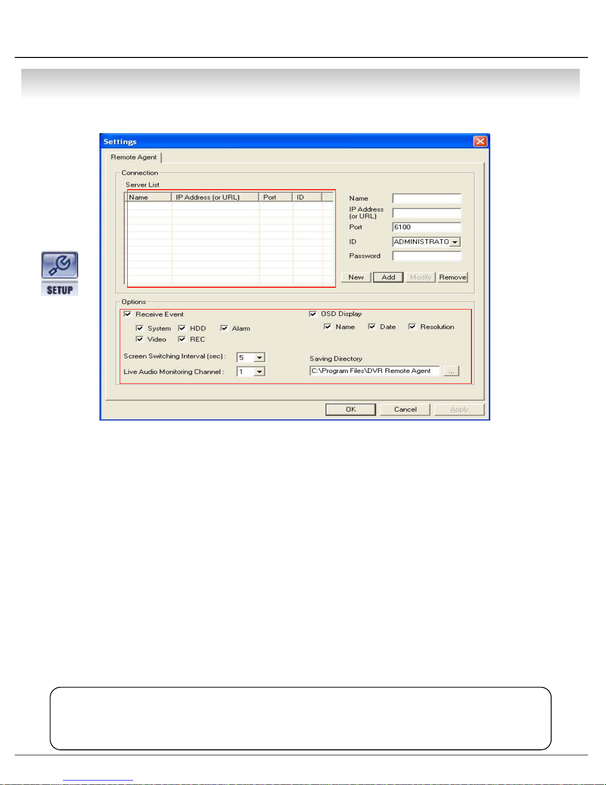
3. Setting
⑫
①
②
③
④
⑤
⑥
⑦
⑪
3.1 Connection ID Setup
① DVR Status : Indicate Present Saving DVR & DVR Information.
② Input Name to Add or Amend DVR.
③ Input DVR IP Address to Add or Amend.
④ Indicate Port No.
⑤ Input ID for Connecting DVR.
⑥ Input Password for Connecting DVR.
⑧⑨⑩
⑦ Click to Input New DVR Information.
⑧ After Input All DVR Information, Add DVR Information at DVR Status.
⑨ After Amend All DVR Information, Applying Change DVR Information.
⑩ Selected DVR Delete at DVR Status.
⑪ Option : Each Option Setup Change
⑫ System Setup : Setup DVR Server from Remote Client, Only Possible when Connected Administrator
• When Change DVR Setup at the Remote Client, DVR Server Setup must be
Tip
1 Non-Activated.
• Administrator ID Max 1, Connectable No of People Max 4
1 (Including Manager, Operator, and Web-Client).
64
• CLIENT
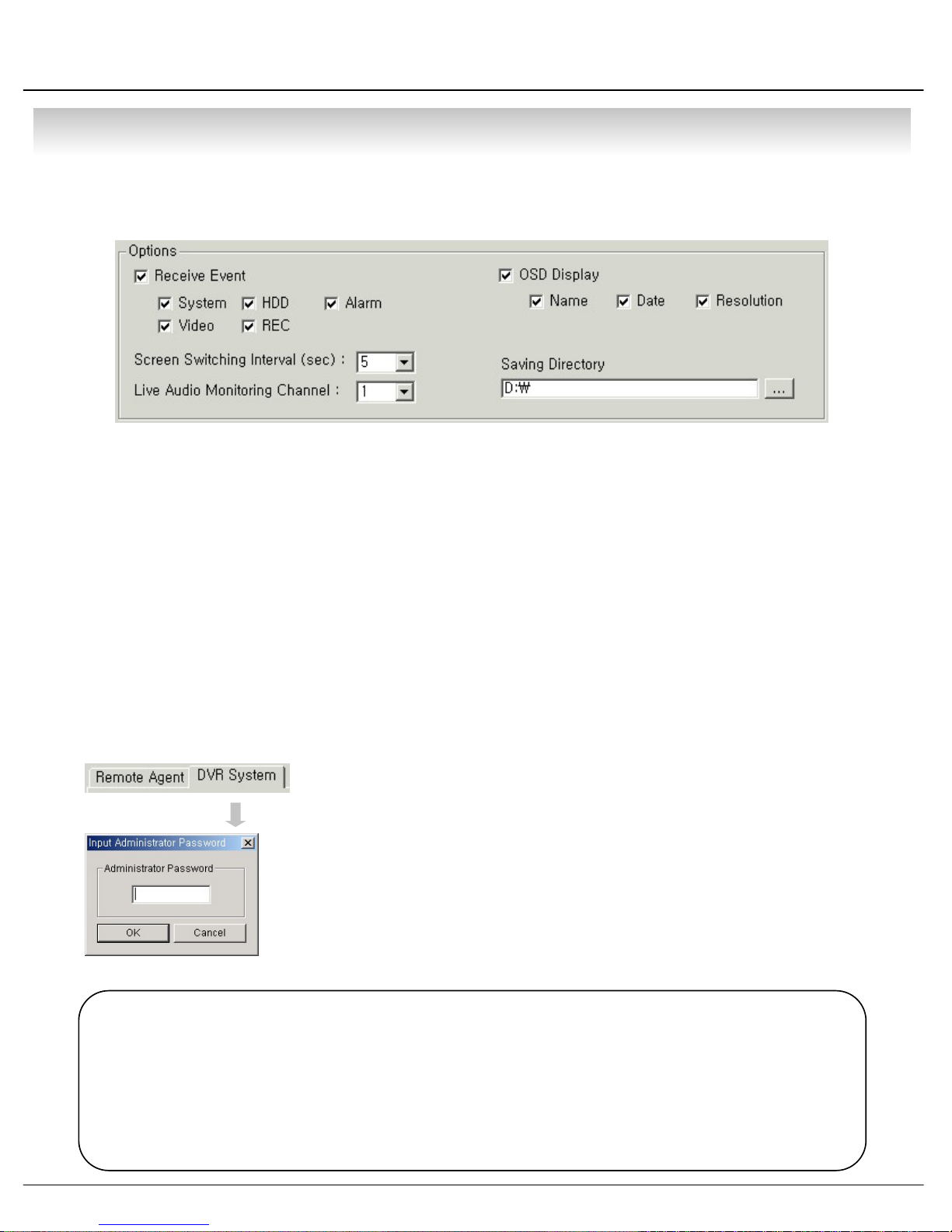
3.2 Option Setting
①
②
③
① Receive Event : Select Kinds of Event as Multiple. Remote Client Only Receive Selected Event.
(System, HDD, Alarm, Video, REC)
② Screen Switching Interval (sec) : During the Monitoring, Select Screen Rotation Interval Time
(From 1 sec. to 300 sec.)
③ Live Audio Monitoring Channel : Select Channel for Listening Audio at Remote Among 4Ch Audio.
④ OSD Display : Select Screen Information.
(Name, Date, Resolution)
⑤ Saving Directory : Designate Remote PC Backup Image Saving Folder.
④
⑤
3.3 DVR Server Remote Setup
• Click DVR System Setup Tap, Password Input Window Open
• DVR System Tap Indicated Only when Connect as Administrator.
• DVR System Setup Possible to Control Almost Every Setup at the Remote.
• When Activate Setup or Changing Setup at the DVR Server,
1 It’s Impossible to Change Setup at the Remote.
• During System Setup at the Remote, DVR Server Setup Start Make to
1 Close Remote System Setup Automatically.
Tip
• Remote Connection ID Authority
Administrator : All Authority for Remote & Possible to Change DVR System Setup
Manager : All Authority for Remote, But Impossible to Change DVR System Setup
Operator : Monitoring & Setup For Live Screen
Web Client : Only Live Image Monitoring
• Max. 4 People Connection Including Every ID, Administrator ID Supply Only One.
After Input Password, Setup Window Pop-up.
65
p
• CLIENT
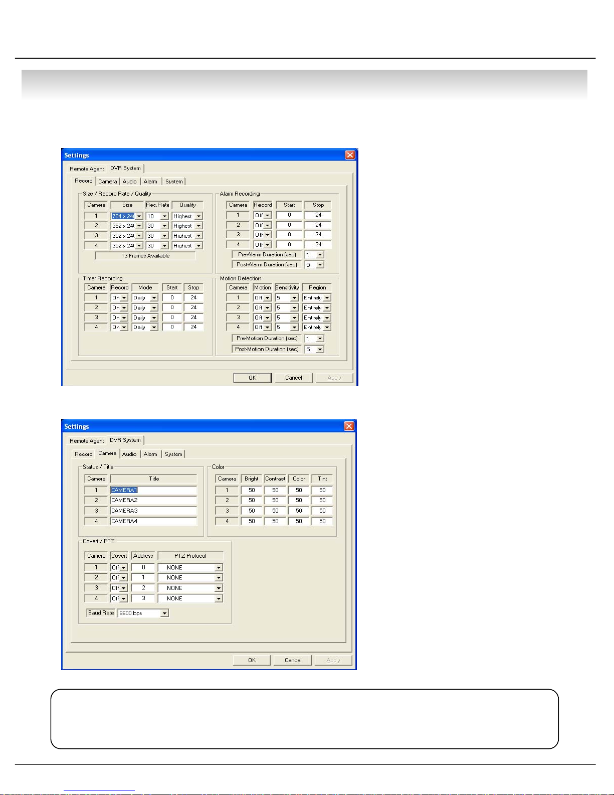
① Record Setup
• Record Size/Rate/Quality Setup
-Setu
1 Resolution & Compression Rate.
• Timer Recording Setup
- Setup Time Schedule for Each Channel.
• Alarm Recording Setup
- Setup for Alarm Recording.
• Motion Detection Setup
- Setup for Motion Detection Recording.
② Camera Setup
• Status/Title Setup
- Setup for Each Camera
(Connection Status or Camera Name).
Each Channel
Tip
• Refer to DVR Server Setup for Each Setup Detail.
•Color Setup
- Setup Color for Each Screen.
• Covert/PTZ Setup
- Setup Each Camera Covert
1 Function & PTZ Protocol.
66
• CLIENT
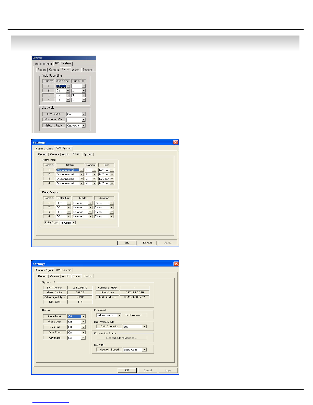
③ Audio Setup
• Audio Recording Setup
- Setup for Each Channel Audio Recording.
• Live Audio Setup
- Live Audio & Two Way Audio Setup for Server.
④Alarm Setup
• Alarm Input Setup
- Setup for Each Channel
1 Alarm Connection & Type.
•Relay Output Setup
- Setup for Each Channel
1 Relay Connection & Mode.
⑤ System Setup
•System Info
- Possible to Watch DVR System
Status.
• Buzzer Setup
- Setup DVR Buzzer Sound On/Off.
• Password Setup
- Change Password for
1 Administrator, Manager, Operator.
• Disk Write Mode
- Setup DVR HDD Overwrite On/Off.
•Connection Status
- Indicate Currently Connected All
1 Remote Client Connection Status.
67
• CLIENT
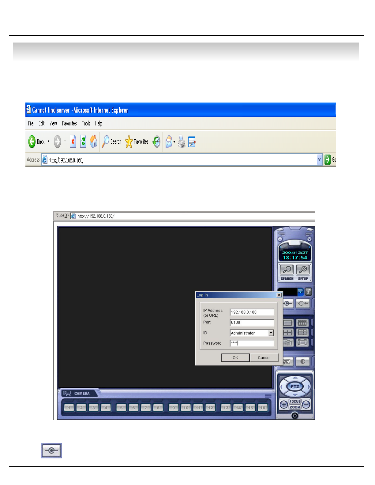
4.WEB Client
• WEB Client Connection
① Input IP Address for DVR Server at the Internet Explorer Address Input Place.
② When Appear Active-X install Message, Please Click Confirm or Continue.
③ Showing Web Client Window at Internet Explorer.
④
Click Connection Button and Pop-up ‘Log In’ Window.
68
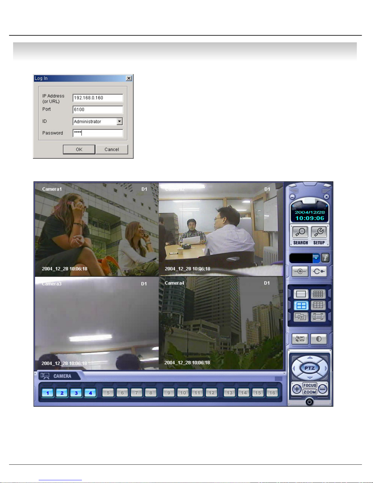
• CLIENT
⑤ IP Address (or URL) : Input DVR IP or URL Address
Port : DVR Client Connection Port is 6100
ID : Select ID (Administrator, Manager, Operator).
(No Difference Authority on Web Client.)
Password : Input Password.
⑥ Only Possible to Monitoring Live Video As soon as Connection.
69

1. Explain Vocubulary
▪ DNS(Domain Name Service)
The domain name system (DNS) is the way that Internet domain names are located and translated into
Internet Protocol addresses. A domain name is a meaningful and easy-to-remember "handle" for an
Internet address. Because maintaining a central list of domain name/IP address correspondences would
be impractical, the lists of domain names and IP addresses are distributed throughout the Internet in
a hierarchy of authority. There is probably a DNS server within close geographic proximity to your
access provider that maps the domain names in your Internet requests or forwards them to other servers
in the Internet.
▪ DDNS(Dynamic Domain Name Service)
When dynamic IP is going to change continuously , DDNS is update automatically about the changing client’s
situation, and notice to Server. So you can receive the DNS service.
▪ DHCP (Dynamic Host Configuration Protocol)
DHCP (Dynamic Host Configuration Protocol) is a communications protocol
manage centrally and automate the assignment of Internet Protocol (IP
network.
▪xDSL
DSL (Digital Subscriber Line) is a technology for bringing high-bandwidth
businesses over ordinary copper telephone lines. xDSL refers to different variations of DSL, such as ADSL,
HDSL, and RADSL. Assuming your home or small business is close enough to a telephone company
central office
bits) per second (of a theoretical 8.448 megabits per second), enabling continuous transmission of motion
video, audio, and even 3-D effects. More typically, individual connections will provide from 1.544 Mbps
Kbps downstream and about 128 Kbps upstream. A DSL line can carry both data and voice signals and the
data part of the line is continuously connected. DSL installations began in 1998 and will continue at a greatly
increased pace through the next decade in a number of communities in the U.S. and elsewhere. Compaq,
Intel, and Microsoft working with telephone companies have developed a standard and easier-to-install form
of ADSL called G.lite
that offers DSL service, you may be able to receive data at rates up to 6.1 megabits (millions of
that is accelerating deployment. DSL is expected to replace ISDN in many areas and to
that lets network administrators
) addresses in an organization's
information to homes and small
to 512
compete with the cable modem
in bringing multimedia and 3-D to homes and small businesses.
70

▪Gateway
A gateway is a network
stopping point can be either a gateway node or a host
point that acts as an entrance to another network. On the Internet, a node or
(end-point) node. Both the computers of
Internet users and the computers that serve pages to users are host nodes. The computers that
control traffic within your company's network or at your local Internet service provider (ISP
gateway nodes. In the network for an enterprise
often also acting as a proxy server
router
, which knows where to direct a given packet of data that arrives at the gateway, and a switch,
and a firewall server. A gateway is often associated with both a
, a computer server acting as a gateway node is
) are
which furnishes the actual path in and out of the gateway for a given packet.
• PPPOE
PPPoE (Point-to-Point Protocol over Ethernet) is a specification for connecting multiple computer
users on an Ethernet
premises equipment, which is the telephone company's term for a modem
local area network to a remote site through common customer
and similar devices.
PPPoE can be used to have an office or building-full of users share a common Digital Subscriber
Line (DSL
), cable modem, or wireless connection to the Internet. PPPoE combines the Point-to-
Point Protocol (PPP
), commonly used in dialup connections, with the Ethernet protocol, which
supports multiple users in a local area network. The PPP protocol information is encapsulated
within an Ethernet frame
Internet service provider (ISP
. PPPoE has the advantage that neither the telephone company nor the
) needs to provide any special support. Unlike dialup connections, DSL
and cable modem connections are "always on." Since a number of different users are sharing the
same physical connection to the remote service provider, a way is needed to keep track of which
user traffic should go to and which user should be billed. PPPoE provides for each user-remote
site session to learn each other's network addresses (during an initial exchange called "discovery").
Once a session is established between an individual user and the remote site (for example, an
Internet service provider), the session can be monitored for billing purposes. Many apartment
houses, hotels, and corporations are now providing shared Internet access over DSL lines using
Ethernet and PPPoE.
71
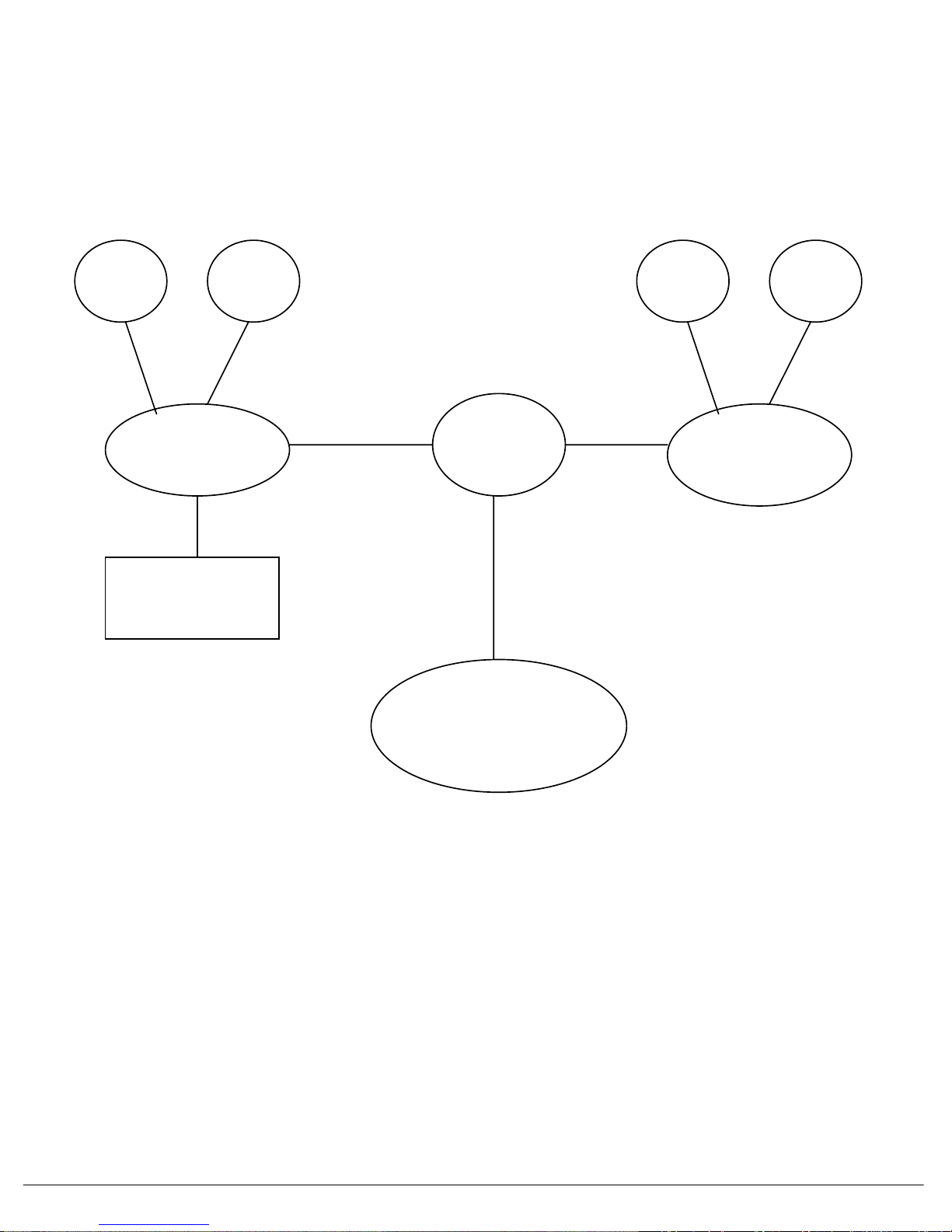
2. Diagram by Dynamic IP
DHCP
Server
DNS
Server
LAN
Environment
In Company
DVR
Internet
Environment
DDNS
DHCP
Server
LAN
Environment
In other Company
DNS
Server
SERVICE
72

■ Certification Date : 20040628
■ Test Report No: E046R-077
■ Model Name : SDS-1204A
■ Certification Date: 20040628
■ Test Report No: E046R-072,E0R6R-073
■ Model Name : SDS-1204A-AV
■ Certification Date : 20040909
■ Certification No : E-A900-04-3784
■ Model Name : IDVR400T-AV

Error Report
Customer RemarkModel Serial No.Date
Error Phenomenon or Special Report
Complete
Unit/KIT
Improve Request
Complementary Measure
 Loading...