


MMXTM
Intelligent Fire Alarm Network
User Guide
LT-893SEC Rev 1
May 2017


Table of Contents
Introduction.............................................................................................................................. 1
About this Manual................................................................................................................. 1
Front Panel Indicators, Controls, and Operation.................................................................. 2
Front Panel Indicators and Control Locations (Model DSPL-420)........................................ 2
Front Panel Indicators and Control Locations (Model DSPL-420-16TZDS)......................... 3
Common Indicators ....................................... ... ... .... ... ....................................................... ... 4
Common Controls.......... ... ... .......................................................... .... ................................... 5
Troubleshooting ...................................................................................................................... 8
Start Up....................................... ....................................................... .... ... ... ... ... .... ... ................ 9
Passcodes............................................................................................................................ 10
Factory Defaults ...................................... ... ... ... ... ....................................................... .... ...... 10
Menu Mode............. ... .... ... ... ... .... ... ... ... .......................................................... .... ................... 11
Front Panel Menu Operation............... ... .... ... ... ... ... .... ... ... ... .... ... ... ... .... ... ... ... ... .... ... ... ... .... ... ... 12
1. Reports Menu................................................................................................................... 12
2. Bypass Menu.................................................................................................................... 21
3. Walk Test Menu................................................................................................................ 25
Alternate Menu Option #3: Manual Control Enable.......... .... ... ... ... .... ... ... ... ... .... ... ... ... .... ... ... 33
4. Day/Night Mode................................................................................................................ 34
5. Set Time ........................................................................................................................... 35
6. Clear Event Log................................................................................................................ 36
7. Clear Verification Counter ................................................................................................ 37
8. Network Restart................................................................................................................ 38
9. Configuration Info ............................................................................................................. 38
10. Choose Configuration..................................................................................................... 39
Paging Operation..................................................................................................................... 40
QMP-5101N and QMP-5101NV Network Master Paging Indicators and Controls............... 40
QMP-5101N/V LEDs ............................................................................................................ 40
QMP-5101N/V Pushbutton Controls.................................................................. ............. ...... 41
QAZT-5302 Paging Selector Panel LEDs ............................................................................ 42
QAZT-5302 Pushbuttons...................................................................................................... 42
Telephone Operation............................................................................................................... 43
QMT-5302N/QMT-5302NV Master Firefighters’ Telephone Indicators and Controls........... 43
Telephone Operation............................................................................................................ 44
QMT-5302N Master Telephone LEDs.................................................................................. 44
QMT-5302N Master Telephone Pushbutton Controls .......................................................... 44
QAZT-5302 Network Firefighters’ Telephone Selector Panel LEDs..................................... 44
QAZT-5302 Network Firefighters’ Telephone Selector Panel Pushbutton Controls............. 44
MMXTM User Guide
i

MMXTM User Guide
Introduction
About this Manual
This user guide provides information on the Command Menu features of the MMXTM Network Fire Alarm and
Audio system which includes MMX-2003-12NDS, MMX-2003-12NXTDS, MMX-2009-12NDS, and MMX-201712NDS. Using the instructions provided in this manual, you will be able to:
• Print reports
• Bypass devices, circuits, loops, and disconnect relays
• Perform a walk test
• Change your passcode
• Clear logs and counters
• Set Day/Night mode
•Set Time
1

Front Panel Indicators, Controls, and Operation
MCG Network
Fire Control System
- System Normal -
May 04, 2016 12:00:00
LCD Display - four lines,
20 characters per line
Cursor buttons, ENTER, MENU,
CANCEL, INFO
Queue controls and
indicators for Alarm,
Supervisory, Trouble,
and Building
Indicators for AC On,
CPU Fault, and
Ground Fault
Controls & Indicators for Signal
Silence, Visual Indicator Test,
System Reset, Fire Drill
Two configurable
switches & amber
LEDs
Controls & Indicators for General
Alarm & Acknowledge (2 stage
systems)
Graphic Display - 24 lines,
40 characters per line
Queue controls and indicators for
Alarm, Supervisory , T rouble, and
Controls & Indicators for Signal
Silence, Visual Indicator Test,
System Reset, Fire Drill
Two configurable switches & amber
LEDs such as General Alarm &
Acknowledge for Two-stage Systems
Cursor buttons:
ENTER,
MENU,
CANCEL,
INFO
Indicators for AC On, CPU Fault, and Ground
Front Panel Indicators and Control Locations (Model DSPL-420)
Note: The General Alarm LED and pushbutton, and the Acknowledge LED and
Graphic Front Panel Indicators and Control Locations (Model DSPL-2440)
pushbutton, are active only on a system configured for Two Stage.
2

Front Panel Indicators and Control Locations (Model DSPL-420-16TZDS)
16 congurable
bi-coloured zone
indicators and 16
trouble indicators
Queue controls and
indicators for Alarm,
Supervisory,
Trouble and Monitor
AC On
Indicator
CPU Fault
Indicator
Ground Fault
Indicator
LCD Display
4 lines
20 characters
Menu
Cancel
Info
Cursor buttons
and Enter button
Control and Indicators for Signal Silence, General Alarm,
Automatic Alarm Signal Cancel, Fire Drill, System Reset,
Visual Indicator Test and Spare programmable Buttons
AUTOMATIC
ALARM
SIGNAL
CANCEL
MMXTM User Guide
LED indicators are amber (trouble or supervisory), red (alarm), or green (AC ON), and may illuminate
continuously (steady) or at one of two flash rates:
• Fast flash: 120 flashes per minute, 50% duty cycle
• Trouble flash: 20 flashes per minute, 50% duty cycle
Paper Labels for Buttons and Indicators
Buttons and indicators are supplied with paper labels. These labels slide into the plastic label templates on the
face of the panel. Paper labels allow for easy English / French selection and custom-printed zone information.
Note: The Acknowledge LED and pushbutton, are active only on a system configured for T wo Stage.
3

Front Panel Indicators, Controls, and Operation
Common Indicators
Buzzer
The buzzer is activated by any of the following:
• Fire alarm: steady
• Supervisory alarm: fast flash rate
• Trouble: trouble flash rate
• Monitor: Configurable to sound at trouble flash rate
If the buzzer turns ON in response to a non-latching trouble or supervisory, it will turn OFF if the condition causing it
goes away and there is no other reason for it to be ON.
AC ON LED
The AC ON LED illuminates steady green while the main AC
power is within acceptable levels. It turns OFF when the
power level falls below the power-fail threshold and the panel
switches to standby (battery) power.
Alarm Queue LED
The Alarm LED flashes red whenever the panel is in alarm.
An alarm results from any alarm on any point or input
programmed as alarm or activation of the manual red General
Alarm button. The Alarm Queue LED will illuminate steadily
once all alarms in the queue have been reviewed using the
Alarm Queue button. Since all alarms are latched until the
panel is reset, the LED will remain ON until then.
ALM
QUEUE
SUP
QUEUE
TBL
QUEUE
BLDG
QUEUE
Supervisory Queue LED
The Supv. (Supervisory) LED flashes amber when there is a supervisory alarm in the panel resulting from any
latching or non-latching supervisory circuit. The LED turns OFF if all non-latching supervisory circuits are restored
and there are no active latching supervisory circuits. The Supv. Queue LED will illuminate steadily once all
supervisory alarms in the supervisory queue have been reviewed using the Supv. Queue button. Latching
supervisory alarms remain active until the panel is reset.
Trouble Queue LED
The Trouble LED flashes amber at the trouble flash rate when the panel detects any trouble condition. The LED
turns OFF after all non-latching troubles are cleared. The Trouble Queue LED will illuminate steadily once all
troubles in the trouble queue have been reviewed using the Trouble Queue button.
Building Queue LED
The BLDG Trouble LED flashes amber at the trouble flash rate when the panel detects any building monito r
condition. It turns OFF after all monitor troubles are cleared.
CPU Fault LED
The CPU Fault LED flashes amber at the trouble flash rate when the main CPU fails.
Ground Fault LED
The Ground Fault LED flashes amber at the trouble flash rate when the Ground Fault Detector detects a ground
fault on any field wiring. It turns OFF after the fault is cleared.
4

Signal Silence LED
The Signal Silence LED flashes amber at the trouble flash rate
after indicating circuits are silenced either by the Signal Silence
button, or by the Auto Signal Silence Timer. It turns OFF after
the signals are re-sounded by a subsequent alarm.
SIGNAL
SILENCE
MMXTM User Guide
FIRE
DRILL
Fire Drill LED
The Fire Drill LED turns ON steady amber while Fire Drill is
GENERAL
ALARM
SYSTEM
RESET
active.
Visual
General Alarm LED
The red General Alarm LED illuminates steadily after the
ACKNOW-
LEDGE
LAMP
Indicator
TEST
Test
General Alarm button is pressed, or after the Auto General
Alarm Timer times out. Once the General Alarm LED turns ON,
it will stay active until the panel is reset.
System Reset LED
CONFIGURABLE
SWITCH/LED 3
CONFIGURABLE
SWITCH/LED 7
The amber System Reset LED will illuminate steadily after the
system reset button has been pressed and the system is resetting.
Acknowledge (or Automatic Alarm Signal Silence) LED
If the panel is configured as a Two Stage system, the Acknowledge LED flashes amber at the fast flash rate
while the General Alarm timer is timing. It turns ON steady amber after the Auto General Alarm Timer is
cancelled by the activation of the Acknowledge or Signal Silence buttons. If the Auto General Alarm Timer timesout and puts the panel into General Alarm, the Acknowledge LED turns OFF.
Visual Indicator Test (Lamp Test) LED
The amber Visual Indicator Test LED will illuminate steadily after the Visual Indicator Test button is pressed and
while system is in visual indicator Test mode.
Configurable LED Indicators
Configurable LED indicators include16 bi-coloured LEDs that are available for alarm, supervisory, and monitor
annunciation paired with 16 trouble LEDs available for trouble annunciation.
Common Controls
LCD Display
The display is a large, four line, 20 character back-lit alphanumeric LCD. It displays information regarding the
panel, its circuits, and devices. An on-screen cursor is controlled by the cursor buttons (located to the right of the
display) for menu selection and control. Report information provided by the LCD display include Alarm Log,
Event Log, Current Levels, Verification, and Maintenance reports.
5

Front Panel Indicators, Controls, and Operation
MENU
CANCEL
ENTER
INFO
Queue Buttons
Use the queue buttons to select a particular queue to review.
•Use the Alarm Queue button to view all alarms. Pressing this button will show the latest alarm on the LCD
display. Use and to view all previous alarms.
•Use the Supervisory Queue button to view all supervisory conditions. Pressing this button will show the latest
supervisory information on the LCD display . Use an d to view all previous supervisory conditions on
the LCD display.
•Use the Trouble Queue button to view all trouble conditions. Pressing this button will show the latest trouble
condition on the LCD display. Use and to view any previous troubles.
•Use the Monitor Queue Button to show all monitor conditions. Pressing this button will show the latest monitor
information on the LCD display. Use and to view all queued monitor conditions.
Queues are displayed on the screen according to a priority
sequence. Queue priority ranking from highest to lowest is as
follows: alarm, supervisory, trouble, and monitor. If, for
example, you are viewing a monitor queue and an alarm
occurs, the display will immediately display the alarm
condition. Also, if there is no activity on the system for 10
seconds after you have pressed a queue button, the display
will switch to the highest priority condition.
Cursor Buttons
Located around the Enter button, the cursor buttons up (previous), down
(next), right, and left allow you to select items on the LCD display. The up
and down buttons scroll through lists in a continuous loop.
Enter Button
SIGNAL
SILENCE
FIRE
DRILL
Use this button to select a displayed item on the LCD display.
Cancel Button
GENERAL
ALARM
SYSTEM
RESET
Use this button to cancel an operation or exit a menu.
Menu Button
ACKNOW-
LEDGE
LAMP
TEST
Use this button to view the Command Menu.
Info Button
CONFIGURABLE
SWITCH/LED 3
CONFIGURABLE
SWITCH/LED 7
Push and hold this button to get detailed information about any displayed
item.
Signal Silence Button
Pressing the Signal Silence button after the panel is in alarm turns ON the Signal Silence LED and deactivates any
silenceable indicating circuits. Non-silenceable circuits are unaffected. Signals will re-sound upon any subsequent
alarm. This button does not function during any configured Signal Silence Inhibit Timer period. It also does not
function if indicating circuits are active as the result of a fire drill. In a Two Stage system, if the Auto General Alarm
Timer has not timed out, the Signal Silence button also performs the same function as the Acknowledge button.
Fire Drill Button
The Fire Drill button activates all programmed and non-disconnected indicating circuits, but does not transmit any
alarms via the city tie or common alarm relay. The Fire Drill button may be programmed to operate specific
indicating circuits. The fire drill is cancelled either by pressing the Fire Drill button again (toggle switch) or if the
panel goes into a real alarm.
6

MMXTM User Guide
General Alarm Button
Activation of the General Alarm button immediately sends the panel into general alarm. It will also re-activate the
signals if they have been silenced during alarm. The general alarm condition remains active until the panel is
reset. Silenceable signals can be silenced using the Signal Silence button.
System Reset Button
The System Reset button resets the panel and all circuits:
•Resets all Latching Trouble Conditions •Resets all Initiating Circuits
•Resets 4-Wire Smoke Supply •Turns off all Indicating (NACs) Circuits
•Turns off Signal Silence, Acknowledge
and General Alarm LEDs
•Turns off Fire Drill
•Stops and resets all Timers •Processes inputs as new events
•Aux Disconnect is not affected
•Reset cannot be activated until the Signal Silence
Inhibit timer has expired
ATTENTION: The System Reset can be global (all control panels) or by defined Node group (one or more
Nodes) as programmed using the MSW-025 MMX
TM
Configurator Software
Acknowledge Button (Two Stage Only)
If the panel is not configured for Two Stage operation, this button could be configured for a different opera tion. If
the panel is configured for Two Stage operation, activation of the Acknowledge button while the Auto General
Alarm Timer is timing (e.g. there is an alarm in the panel but it is still in the first stage) cancels the timer and turns
the Acknowledge LED on steady amber.
Lamp Test Button
Pressing and holding the Lamp Test button causes all front panel indicators to illuminate and sounds the buzzer
steadily. Bi-coloured LEDs will illuminate twice to show both colors. If lamp test is active for more than one
minute, the Common Trouble LED activates.
Configurable Switches/LEDs
These two switches and LEDs can be used for any function listed in the MSW-025 MMX
TM
Configurator
Software. Such functions include Buzzer Silence, Auxiliary Disconnect, Total Evacuation, Bypass, System
Inputs, and Fan Control.
7

Troubleshooting
Message Description
Unconfigured CPU Trouble
I/O Adder Mismatch Trouble
Display Mismatch Trouble
Unconfigured Device
Trouble
Printer Data Loss Trouble
Slave (RAXN-LCDs)
Configuration Version
Mismatch Trouble
Slave (RAXN-LCDs)
Configuration Address
Mismatch Trouble
Slave Configuration Type
Mismatch
Wrong Device Type
Multiple Unconfigured
Device Trouble
Data Link Failure
Data Link Trouble
Program Version Mismatch
(displayed on the RAXNLCD only)
Configuration Data Error
(RAM)
Configuration Data Error
(FLASH)
This message appears when additional annunciators or loop adders are
physically connected to the panel but are not programmed in the Configurator
or are configured for the wrong address.
This message displays when the hardwired adder modules are in the wrong
order or the wrong quantity. If the number of physical hardwired adder modules
does not match the number of modules listed in the configuration, the panel will
display this message. It will also display this message if the adder modules are
not connected.
This message displays when the number of display modules (RAX-1048/TZ,
FDX-008, and IPS-2424) connected to the panel do not match the number and
the order of display modules listed in the configuration. Make sure the display
modules are connected.
This message displays when an analog device is physically installed but does
not appear in the configuration program.
This message displays when a printer is configured but not physically
connected to the panel and a message is sent to the printer. Pressing the
System Reset button will clear this trouble.
This message displays when the firmware versions on all the CPUs are not
compatible.
This message displays when the address(es) of the configured slaves does not
match.
This message displays if the physical loop adder does not match the loop adder
type specified in the configuration program. For example, you will see this
message if the physical adder module is an ALC-396 and the specified adder
module in the configuration program is an ALC-H16.
This message displays if the type of analog device does not match the type that
is listed in the configuration program. For example, you will see this message if
an ionization sensor at address 013 is physically connected to the panel but the
configuration program has address 013 listed as a photoelectric sensor (or vice
versa).
This message displays if there are two identical (duplicate) devices at the same
address on the same loop.
This message displays if the panel cannot communicate with a remote
annunciator or an internal CPU on an adder module.
This message displays when the panel has a communication error with a
remote annunciator.
This message displays when the RAXN-LCD firmware version is not compatible
with the FX-2000N firmware version.
This message displays if the system is overloaded and risks resetting itself.
Reload the Configurator and/or reboot the system by powering it down and then
powering it up.
This message displays if the system is overloaded and risks resetting itself. If
this error should occur, please report it to Secutron’s Technical Support
Department.
8

MMXTM User Guide
Initial system self
checks in process...
Start Up
Before start up, disconnect the network cable.
When the system is plugged in and the batteries are connected, the front display will show:
Let the system initialize for approximately one to two minutes.
Download the configuration at each Node using a laptop computer and MMX
Nodes have been downloaded, connect the network and select the Network Restart (see page 31) at the CACF
(Central Alarm and Control Facilities) or main node.
If there is an alarm, supervisory, trouble, or monitor condition in the system, pressing the appropriate queue
button and holding will display information on the cause of the alarm, supervisory, trouble, or monitor
device activation.
TM
Configurator. Once all the
Note: To display the configuration software version, press , then hold .
9

Start Up
MGC Network
Fire Alarm Control Panel
Normal Condition
June 17, 2016
THESE BUTTONS
REPRESENT THE
CORRESPONDING
NUMBER IN THE
MENU MODE
0 1 2 3
Pressing the Alarm Queue button represents the number 0,
Pressing the Supv. Queue button represents the number 1,
Pressing the Trouble Queue button represents the number 2,
Pressing the BLDG Queue button represents the number 3.
NOTE: THERE IS NO PASSCODE NUMBER AVAILABLE ABOVE 3, THEREFORE, PASSCODES
ARE MADE UP OF NUMBERS 0, 1, 2, AND 3 AND CAN BE UP TO 20 DIGITS LONG.
ALM
QUEUE
SUP
QUEUE
TBL
QUEUE
BLDG
QUEUE
MENU
CANCEL
ENTER
INFO
Passcodes
Factory Defaults
FROM THE FACTORY PASSCODES ARE:
Level 1: 1111
Level 2: 2222
Level 3: 3333
A passcode is not required for Level 0 access. Passcodes provide three different levels of menu access. Default
passcode 1 111 allows Level 1 Access. Default passcode 2222 allows Level 2 access. Default passcode 3333 allows
Level 3 access.
ACCESS LEVELS FOR THE FOLLOWING FEATURES, ARE DEFINED (SET AT THE FACTORY) AS:
Reports: 0
Aux. Bypass: 0
Device Bypass: 1
Walk Test: 1
Day/Night Mode: 0
Set Time: 1
Clear Event Log: 2
Clear Verification Count: 2
Config/Network Reset: 2
Manual Enable: 0
Note: You can change these access levels via the MMXTM Configurator MSW-025.
10

Menu Mode
Press the button to activate the menu mode. The menu is broken down as follows:
Menu Submenu Description How to Use
Alarm Log View or print the Alarm Log. See page 13.
Event Log View or print the Event Log. See page 13.
Current Levels View or print the Current Levels. See page 14.
Verif. Count View or print the Verified Count. See page 15.
MMXTM User Guide
1. Reports
Maint Report View or print the Maintenance Report. See page 16.
Current PWs View or print Pulse Width Current Report See page 17.
Obscuration View or print the obscuration values See page 18.
CO Maint Report View or print CO detector Maintenance Report See page 19.
Battery Voltage View or print Battery Voltage reading See page 20.
Device/Circuit Bypass/unbypass a Device/Circuit. See page 22.
2. Bypass
Relay disc Disconnect/reconnect all relays. See page 25.
Input Zone Disconnect/reconnect input zones per node See page 25.
Audible Test Perform an audible walktest. See page 26.
3. Walk Test
Silent Test Perform a silent walktest. See page 27.
Assisted (if
configured)
Assisted walktest for large systems See page 29.
4. Day/night mode N/A Select day or night mode. See page 34.
5. Set time N/A Set the time and date. See page 35.
Alarm Log Clear the Alarm Log. See page 36.
6. Clear Event
Log
Event Log Clear the Event Log. See page 36.
All Logs Clear all the logs. See page 36.
7. Clear
Verification Count
8. Network
Restart
N/A Clear all verification counters. See page 37.
N/A
9. Config Info N/A Select this feature to view See page 38.
10. Choose
Config
N/A
Note: If you have used the Configurator to program the “Enable Required” option in the Command Menu, th e
Command Menu list will appear differently than that which is shown above. Menu option three will read
“Enable Required”, and “Walk Test” will move to menu option four. All subsequent menu options will
similarly be renumbered. For more information on the Enable Required option, see page 33.
Select this once system configuration download
is completed.
Select the configuration version you wish to
download into the system.
See page 38.
See page 39.
11

Front Panel Menu Operation
- Command Menu1 Reports
2 Bypass
3 Walktest
4. Day/night mode
5. Set time
6. Clear Event Log
7. Cle ar Ve rif Co unt
8. Network Restart
9. Config Info
10. Choose Config
^
Enter passcode for
level 1 or higher:
^
- Reports Menu1 Alarm Log
2 Event Log
3 Current
4. Verif. Count
5. Maint Report
6. Current PWs
7. Obscuration
8. CO Maint Report
9. Battery Voltage
1. Reports Menu
Use the Reports Menu to print the Alarm Log, Event Log, Current Levels, Verified Counts, Maintenance report,
Current PWs, Obscuration, CO Maintenance report, and Battery Volt age. You can view on screen, or print directly to
a printer connected to the panel, or to your laptop comput er.
Note: To print a report to a printer or to a laptop (using HyperTerminal), the printer output
must be enabled via the Configurator.
To enter the Reports Menu, you must be in the Command Menu. To enter the Command Menu, press when
the display is in normal mode.
Step 1: Select the Reports Menu
1. Use and to scroll the cursor to “Reports”.
Step 2: Enter your passcode (if required)
Step 3: Select the option you would like to view
The following subsections provide instructions on using each Reports Menu option.
12
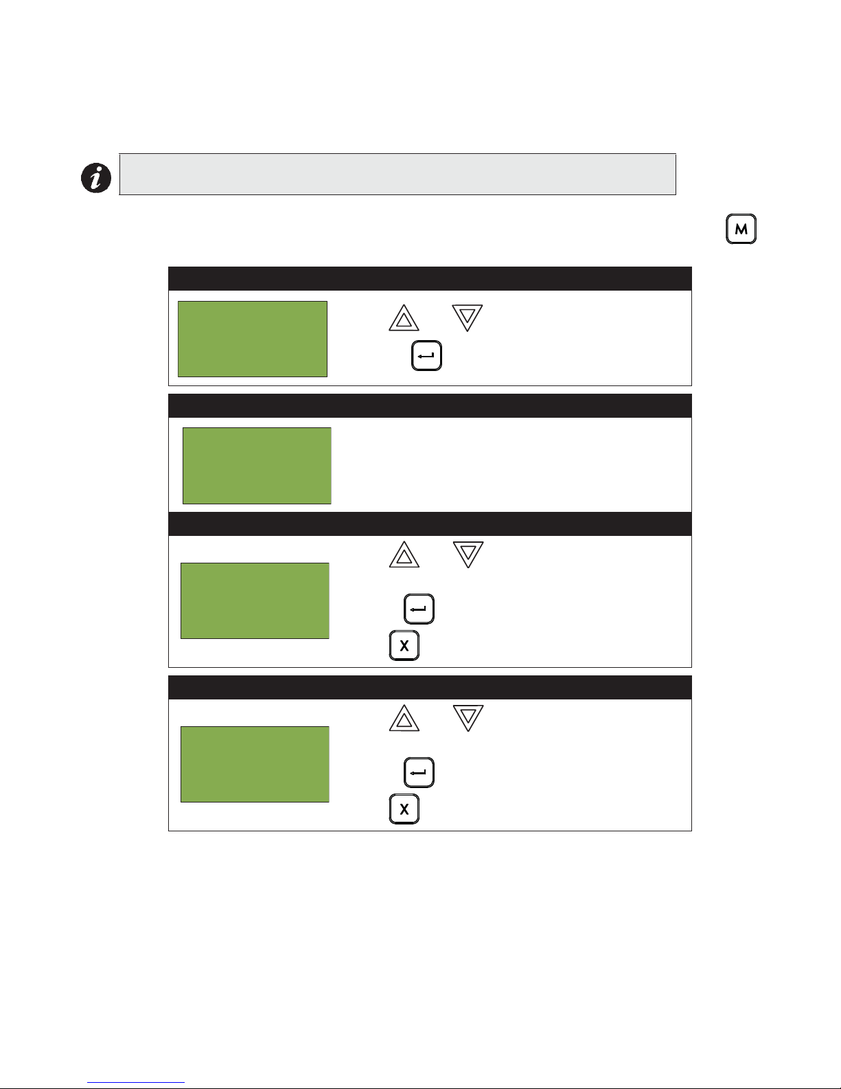
2. Press to select the Reports Menu.
Enter your passcode. See page 10 for instructions on
entering passcodes.
1. Use and to scroll the cursor through the
menu.
2. Press to select an option.
3. Press to exit and return to the Reports Menu.
Repeat to exit to the Command Menu.

MMXTM User Guide
- Reports Menu 1 Alarm Log
2 Event Log
3 Current Levels
^
- Report to 1 Printer
2 Screen
- Reports Menu 1 Alarm Log
2 Event Log
3 Current Levels
^
Alarm Log
The Alarm Log reports on all alarm events. Alarm events are listed in order of the most recent event to the
earliest. The maximum number of recorded alarm log entries is 1000. Once the system reaches 1000 entries,
any new entry will cause 500 of the oldest entries to be deleted.
Step 1: Select the Alarm Log
1. Use and to scroll to “Alarm Log”.
2. Press to continue.
At this point the display will vary, depending on whether or not a printer is connected to the panel.
If a printer is not connected to the panel, the Alarm Log will print to the display.
• Use and to scroll the cursor through the log.
• Hold down for more information on the logged event.
Press to exit to the Reports Menu.
If a printer is connected to the panel, follow Step 2, below.
Step 2: Print the Alarm Log
•To print the Alarm Log to the printer, press
when the cursor flashes beside “Printer”.
•T o print the Alarm Log to the screen, press then
to select “Screen”. Follow the instructions
above to navigate the Alarm Log.
Event Log
The Event Log reports on all events: alarms, tro ubles, an d button pushes. Event s are liste d in o rder of the latest
(most recent) event to the earliest. The maximum number of recorded event log entries is 2000. Once the
system reaches 2000 entries, any new entry will cause 1000 of the oldest entries to be deleted.
Step 1: Select the Event Log
1. Use and to scroll the cursor to “Event
Log”.
2. Press to continue.
At this point the display will vary, depending on whether or not a printer is connected to the panel.
If a printer is not connected to the panel, the Event Log will print to the display.
• Use and to scroll the cursor through the log.
• Hold down for more information on the logged event.
• Press to exit to the Reports Menu.
13

Front Panel Menu Operation
- Report to 1 Printer
2 Screen
- Reports Menu 1 Alarm Log
2 Event Log
3 Current Levels
^
- Report to 1 Printer
2 Screen
-Select Loop NumberLoop: A
L L
If a printer is connected to the panel, follow Step 2, below.
Step 2: Print the Event Log
•To print the Alarm Log to the printer, press
when the cursor flashes beside “Printer”.
•To view the Alarm Log on the screen, press
then to select “Screen”. Follow the
instructions above to navigate the Event Log.
Current Levels
This option reports on the current levels of addressable devices.
Step 1: Select Current Levels
1. Use and to scroll the cursor to “Current
Levels”.
2. Press to select the Current Levels submenu.
Step 2: Print or View the Current Levels
•To print the Current Levels report to the printer, press
when the cursor flashes beside “Printer”.
•To view the Current Levels report on the screen,
press then to select “Screen”. Follow
the instructions above to navigate the Current Levels.
Step 3: Select loop number
•Select a loop number by using and to
scroll through the numbers, or
•Select all loop numbers by pressing . Wait five
seconds. Use and to scroll the cursor
through the loops.
If you view the Current Levels on the screen,
• Use and to scroll the cursor through the log.
• Press and hold for more information on the current level.
• Press to exit to the Reports Menu.
14

MMXTM User Guide
- Reports Menu 2 Event Log
3 Current Levels
4 Verif Count
^
^
- Report to 1 Printer
2 Screen
-Select Loop NumberLoop: A
L L
For example, if you select loop two, the screen will appear as follows:
Loop 2 Address 001
Low Profile ION Det
Current level: 846
Percent alarm: 0%
• The first and second lines pinpoint the exact device.
•The current level is a point of reference number that is helpful to our technicians.
•The percent alarm shows how close the device is to going into alarm: 0% is the least likely, and 80% is the
most likely.
Verified Counts
This option reports on any pre-alarmed devices that are set to verification mode. This report lists each time a
device pre-alarms. If no devices are set to verification mode, then no report will display.
Step 1: Select Verified Counts
1. Use and to scroll the cursor to “Verif
Counts”.
2. Press to continue.
Step 2: Print or View the Verified Counts
• To print the Verified Counts to the printer, press
when the cursor flashes beside “Printer”.
•T o print the Verified Counts to the screen, press
then when the cursor flashes beside “Screen”.
Step 3: Select loop number
•Select a loop number by using and to
scroll through the numbers, or
•Select all loop numbers by pressing and
waiting five seconds. Use and to scroll
the cursor through the loops.
15

Front Panel Menu Operation
No verified devices
found.
Loop 2 Address
005
Low Profile ION
Det
- Reports Menu 3 Current Levels
4 Verified Count
5 Maint Report
^
^
- Report to 1 Printer
2 Screen
-Select Loop NumberLoop: _ _ _
Step 4: If the display shows...
...the display will return to the Reports Menu.
OR
If the display shows...
•Press and hold to view the details.
•Use and to scroll the cursor through the
records.
•Press to exit to the Reports Menu.
Maintenance Report
This option reports on all devices that are greater than 60% of alarm.
Step 1: Select Maintenance Report
1. Use and to scroll the cursor to “Maint
Report”.
2. Press to continue.
Step 2: Print or View the Maintenance Report
• To print the Maintenance Report to the printer,
press when the cursor flashes beside “Printer”.
•To print the Maintenance Report to the screen, press
then when the cursor flashes beside
“Screen”.
Step 3: Select loop number
•Select a loop number by using and to
scroll through the numbers, or
•Select all loop numbers by pressing and
16
waiting five seconds.

Step 4: If the screen shows...
No dirty devices
found.
Loop 2
Address 001
Low Profile ION
Det
^
- Reports Menu 6 Current PWs
7 Obscuration
8 CO Maint
9 Battery Voltage
- Report to 1 Printer
2 Screen
...the display will return to the Reports Menu.
OR
If the display shows...
•Press and hold to view the details.
•Use and to scroll the cursor through the
records.
•Press to exit to the Reports Menu.
Current PWs
This option reports on the current levels of addressable devices.
Step 1: Select Current Levels
MMXTM User Guide
1. Use and to scroll the cursor to “Current PWs”.
2. Press to select the Current PWs
submenu.
Step 2: Print or View Current Levels
• To print the Current Levels report to the printer,
press when the cursor flashes beside
“Printer”. Go to Step 3.
• To view the Current Levels log on the screen, press
then to select “Screen”. Go to Step 3.
17

Front Panel Menu Operation
-Select Node & Loop Node: A
L L
Node 33 Lp2 Addr 1
Photo Detector
1: 0 2: 0 3: 0
4: 0 5: 0
^
- Reports Menu 6 Current PWs
7 Obscuration
8 CO Maint
9 Battery Voltage
- Report to 1 Printer
2 Screen
Step 3: Select Node and Loop number
• Select a Node and Loop number by using
and to scroll through the numbers.
• Select the Node by pressing .
• Select the loop number by pressing . Use
and to scroll the cursor through the
Current Levels, if viewing on the screen.
• Press to exit to the Reports Menu.
An example of the information displayed on screen:
The first and second line pinpoint the exact device.
Obscuration
This option reports on the obscuration levels of the smoke detectors.
Step 1: Select Obscuration
1. Use and to scroll the cursor to
“Obscuration”.
2. Press to select the Obscuration
submenu.
Step 2: Print or View Obscuration
• To print the Obscuration report to the printer, press
when the cursor flashes beside “Printer”.
Go to Step 3.
• To view the Obscuration log on the screen, press
then to select “Screen”. Go to Step 3.
18

Step 3: Select Node and Loop number
-Select Node & Loop Node: A
L L
Node 33 Lp2 Addr 1
Phot o Dete c t or
C u r r e n t O b s c : 0 . 0 0 %
^
- Reports Menu 6 Current PWs
7 Obscurtion
8 CO Maint
9 Battery Voltage
- Report to 1 Printer
2 Screen
• Select a Node and Loop number by using and
to scroll through the numbers.
• Select the Node by pressing .
• Select the loop number by pressing . Use
and to scroll the cursor through the
Obscuration, if viewing on the screen.
• Press to exit to the Reports Menu.
An example of the information displayed on scre e n:
The first and second line pinpoint the exact device.
Below that is the present obscuration percentage of
the device.
MMXTM User Guide
CO Maint
This report specifies which CO device (if used) needs to be replaced.
Step 1: Select CO Maint
1. Use and to scroll the cursor to “CO
Maint”.
2. Press to select the CO Maint submenu.
Step 2: Print or View CO Maint
• To print the Obscuration report to the printer, press
when the cursor flashes beside “Printer”.
Go to Step 3.
• To view the CO Maint log on the screen, press
then to select “Screen”. Go to Step 3.
19

Front Panel Menu Operation
-Select Node & Loop Node: A
L L
Node 33 Lp2 Addr 1
R e p l a c e C O d e t e c t o r
^
^
- Reports Menu 6 Current PWs
7 Obscuration
8 CO Maint
9 Battery Voltage
- Report to 1 Printer
2 Screen
Step 3: Select Node and Loop number
• Select a Node and Loop number by using and
to scroll through the numbers.
• Select the Node by pressing .
• Select the loop number by pressing . Use
and to scroll the cursor through the CO
Maint, if viewing on the screen.
• Press to exit to the Reports Menu.
An example of the information displayed on screen:
The first and second line pinpoint the exact CO
device which needs to be replaced. The other report
will say “No CO Devices to report”.
Battery Voltage
This option reports on the voltage level of the battery.
Step 1: Select Battery Voltage
1. Use and to scroll the cursor to “Bat-
tery Voltage”. Press to continue.
Step 2: Print or View the Battery Voltage Report
• To print the Battery Voltage Report to the printer,
press when the cursor flashes beside
“Printer”.
• To view the Battery Voltage on the screen, press
“Screen”.
then when the cursor flashes beside
20

MMXTM User Guide
-Select NodeLoop: A
L L
Battery Voltage
Node 02
Battery: 27.75V
- Command Menu 1 Reports
2 Bypass
3 Walktest
^
Enter passcode for
level 1 or higher:
- Bypass Menu 1 Device /Circuit
2 Relay disc
3 Input Zone
Step 3: Select Node
• Select a Node by using and to scroll
through the numbers, then when the correct
Node number appears.
Step 4: Pwr Src Report
The battery voltage will be displayed as per this
example.
2. Bypass Menu
Use the Bypass Menu when you want to bypass or unbypass devices, hardware circuits, complete addressable
loops, or outputs such as relays and signals.
To enter the Bypass Menu, you must be in the Command Menu. To enter the Command Menu, press
when the display is in normal mode.
Step 1: Select the Bypass Menu
1. Use and to scroll the cursor to “Bypass”.
2. Press to select the Bypass Menu.
Step 2: Enter your passcode (if required)
Enter your passcode. See page 10 for instructions on
entering passcodes.
Step 3: Select the option you would like to view
1. Use and to scroll the cursor through the
Bypass Menu.
2. Press to select an option.
The following subsections provide instructions on using each Bypass Menu option.
Press to exit and return to the Bypass Menu.
Repeat to exit to the Command Menu.
21

Front Panel Menu Operation
- Bypass Menu 1 Device /Circuit
2 Relay Disc
3 Input Zone
Enter passcode for
level 1 or higher:
- Select Device Node: 0
Loop: 0
Device: 0 0 0
Strobe Outpu t
Floor 2
L0 000 not
bypassed. Bypass? Y
Device/Circuit Bypass
Use this option if you want to bypass or unbypass a device or circuit from the panel. Usually this is done when you
need to add, remove, repair, or in vestigat e a device or circuit .
To unbypass the device or circuit, follow the same procedure for device/circuit bypass.
Step 1: Select Device/Circuit
Press when the cursor is flashing beside
“Device/Circuit” to select a device.
Step 2: Enter your passcode
Enter your passcode. See page 10 for instructions on
entering passcodes.
Step 3: Select a device
1. Use and to select the node, loop and
device number.
2. Enter the node number, then press .
3. Enter the loop number, then press .
4. Enter the device number, pressing and
as needed to move left and right.
5. Press to continue.
Step 4: Bypass the device/circuit
1. The systems now asks you whether or not you would
like to bypass or unbypass the device. Use and
to select “yes” or “no”.
2. Press to continue.
At this point the display will vary, depending on your choice:
• If you selected “yes”, the system will display the message “Device/Circuit bypassed (unbypassed), then it will
return to the Bypass Menu.
• If you selected “no”, the system will display the message “Operation cancelled”, then it will return to the
Bypass Menu.
22

MMXTM User Guide
Warning: This output
device is active.
Do you really want
to unbypass it? Y
- Bypass Menu 1 Device /Circuit
2 Relay Disc
3 Input Zone
Common aux relays
currently connected
Disconnect? Y
- Bypass Menu 1 Device /Circuit
2 Relay Disc
3 Input Zone
Unbypassing an active device/circuit
When you unbypass a device or circuit that went into alarm while it was bypassed, you will see the following
message:
If you select “yes” to unbypass this device, the system will immediately go into alarm. To avoid this problem,
press the System Reset button before unbypassing a device or circuit.
Relay Disconnect
This option is useful if you want to disconnect or reconnect the aux relays.
Step 1: Select Relay Disconnect
1. Use and to scroll the cursor to “Relay
Disc”.
2. Press to continue.
Step 2: Select “yes” or “no”
1. The systems now asks you whether or not you would
like to bypass the aux relays. Use and to
select “yes” or “no”.
2. Press to continue.
At this point the display will vary, depending on your choice:
• If you selected “yes”, the display will either show the message “Relays disconnected” or “Relays
reconnected”, then it will return to the Command Menu.
• If you selected “no”, the display will show the message “Operation cancelled”, then it will return to the
Command Menu.
Input Zone Bypass
WARNING: Bypassing an input zone will disable all input devices in that loop.
Use this option if you want to bypass an entire zone of addressable devices from the panel. Usually this is done
during building maintenance.
To unbypass the input zone, follow the same procedures for input zone bypass.
Step 1: Select Input Zone Bypass
1. Use and to scroll the to “Input Zone”.
2. Press to continue.
23

Front Panel Menu Operation
-Select Input ZoneNode: 1
CPU: 1
Nd: __ CPU:__ Zn:__
Bypass? Y
W arning: This zone is
active. Do you really
want to unbypass
it? Y
Step 2: Select a loop number
1. Use and to select the Node and CPU
number.
2. Press to continue.
Step 3: Bypass the loop
1. The systems now asks you whether or not you would
like to bypass or unbypass the input zone.
Use and to selec t “ye s ” or “no ”.
2. Press to continue.
At this point the display will vary, depending on your choice:
• If you selected “yes”, the display will either show the message “Input Zone bypassed” or “Input Zone
unbypassed”, then return to the Command Menu.
• If you selected “no”, the display will show the message “Operation cancelled” and will then return to the
Command Menu.
Unbypassing an active loop
When you unbypass a input zone that went into alarm while it was bypassed, you will see the following message:
If you select “yes” to unbypass this loop, the system will immediately go into alarm. T o avoid this problem, press the
System Reset button before unbypassing the loop.
24
MMXTM User Guide
- Command Menu 1 Reports
2 Bypass
3 Walktest
Enter passcode for
level 1 or higher:
- Walktest 1 One Man
2 Walktest report
- Walktest 1 Audible Test
2 Silent Test
3. Walk Test Menu
Use the Walk Test Menu when you want to test the devices in a system. Performing a walk test will place the
system in trouble (non-latching).
Note: Walk test records that are viewed on the screen will be stored in the event log.
To enter the Walk Test Menu, you must be in the Command Menu. To enter the Command Menu, press
when the display is in normal mode.
Step 1: Select the Walk Test Menu
1. Use and to scroll the cursor to “Walktest”.
2. Press to select the Walk Test Menu.
Step 2: Enter your passcode (if required)
Enter your passcode. See page 10 for instructions on
entering passcodes.
Step 3: Select the option you would like to view
1. Use and to scroll the cursor through the
menu.
2. Press to select an option.
Press to exit and return to the Command Menu.
Step 4: Select the One Man to see this next menu
1. Use and to scroll the cursor through the
menu.
2. Press to select an option.
Press to exit and return to the Command Menu.
The subsections following provide instructions on using each One Man Walk Test Menu option, Audible T e st and
Silent Test.
25

Front Panel Menu Operation
- Walktest 1 Audible Test
2 Silent Test
- Walktest Timeout 6 hours
- Walktest 1 Start
2 Resume
OneMan
A:xxxx D:xxxx R:xxxx
T:xxxx D:xxxx R:xxxx
Press CANCEL to end
Audible Test
During this test, alarm activation of any input device will activate all signals for one half second. Trouble activation
on any input device will activate all signals continuously for one second. If audio amplifier is configured for alarm
and trouble events, it will sound words “Alarm” and “Trouble” respectively.
Note: Audible devices connected to an addressable output module will not sound in Audible Test mode.
Step 1: Select Audible Test
1. Use and to scroll the cursor to “Audible
Test”.
2. Press when the cursor flashes beside
“Audible Test” to select the Audible Test.
Step 2: Select duration of Walk Test
1. The default duration of Walk Test is 6 hours. To
choose another time duration, use the and
to scroll the cursor to the desired duration time.
Valid range is from 1 hour to 12 hours.
Press to select the Walk Test duration.
Step 3: Start the Walk Test
Start or Resume Test for device inspection.
1. Select Start to begin a Walk Test.
2. Select Resume to continue the Walk Test.
As the test runs, the Alarms and Troubles count will
increase as they are recorded (logged) during the
Audible Test.
Press to end the walk test at any time.
Step 4: Main Walk Test Screen
During the Walk Test the display will be as shown.
A = number of Walk Test alarm events
T = number of Walk Test trouble events
D = number of duplicate alarm and trouble events
R = number of remaining alarm and trouble events from
the Walk Test list
Use and to scroll the cursor through the devices in the Walk Test list. Pressing the up/down keys will
switch the view to display the Walk Test list. This view allows selection of the device to be tested.
26

MMXTM User Guide
Nnn Lnn Adrnnnnnnnn
A: nnn T:nnn
Tag 1
Tag 2
- Walktest 1 Audible Test
2 Silent Test
- Walktest Timeout 6 hours
- Walktest 1 Start
2 Resume
Step 5: Device View During the Walk Test
During the Walk Test the device display will be as
shown.
A = total number of alarm events for the device.
T = total number of trouble events for the device.
Press or to switch to the Main Walk Test screen.
Press to exit the Walk Test at anytime.
Silent Test
During this test, alarm and trouble activation of any input device will be recorded by the system but it will not
sound the signals. For the system to register a trouble, you must keep the device in a trouble condition for 10
seconds.
Step 1: Select Silent Test
1. Use and to scroll the cursor to “Silent
Test”.
2. Press . The test will now begin.
Step 2: Select duration of Walk Test
1. The default duration of Walk Test is 6 hours. To
choose another time duration, use the and
to scroll the cursor to the desired duration time.
Valid range is from 1 hour to 12 hours.
Press to select the Walk Test duration.
Step 3: Start the Walk Test
Start or Resume Test for device inspection.
1. Select Start to begin a Walk Test.
2. Select Resume to continue the Walk Test.
As the test runs, the Alarms and Troubles count will
increase as they are recorded (logged) during the
Audible Test.
Press to end the walk test at any time.
27

Front Panel Menu Operation
OneMan
A:xxxx D:xxxx R:xxxx
T:xxxx D:xxxx R:xxxx
Press CANCEL to end
Nnn Lnn Adrnnnnnnnn
A: nnn T:nnn
Tag 1
Tag 2
Step 4: Main Walk Test Screen
During the Walk Test the display will be as shown.
A = number of Walk Test alarm events
T = number of Walk Test trouble events
D = number of duplicate alarm and trouble events
R = number of remaining alarm and trouble events from
the Walk Test list
Step 5: Device View During the Walk Test
During the Walk Test the device display will be as
shown.
A = total number of alarm events for the device.
T = total number of trouble events for the device.
Press or to switch to the Main Walk Test screen.
Press to exit the Walk Test at anytime.
28

MMXTM User Guide
- Command Menu 1 Reports
2 Bypass
3 Walktest
Enter passcode for
level 1 or higher:
- Walktest 1 Assisted
2 Walktest report
- Walktest 1st Floor
2nd Floor
Assisted Walk Test
Assisted Walk Test must be configured using the Configurator. When the Assisted Walk Test is configured, the
One Man Walk Test is replaced by the Assisted Walk Test. The Assisted Wall Test shall be in silent mode only.
To enter the Walk Test Menu, you must be in the Command Menu. To enter the Command Menu, press
when the display is in normal mode.
Step 1: Select the Walk Test Menu
1. Use and to scroll the cursor to “Walktest”.
2. Press to select the Walk Test Menu.
Step 2: Enter your passcode (if required)
Enter your passcode. See page 10 for instructions on
entering passcodes.
Step 3: Select the Assisted Walk Test option
1. Use and to scroll the cursor through the
menu.
2. Press to select the “Assisted” option.
Press to exit and return to the Command Menu.
Step 4: Select the Assisted Walk Test to see this next menu
1. Use and to scroll the cursor through the
menu.
2. Press to select an area for testing.
3. Start inspecting devices. All alarm and trouble events
shall be saved in the Walk Test log.
Press to exit and return to the Command Menu.
29

Front Panel Menu Operation
1st Floor
A:xxxx D:xxxx R:xxxx
T:xxxx D:xxxx R:xxxx
Press CANCEL to end
Nnn Lnn Adrnnnnnnnn
A: nnn T:nnn
Tag 1
Tag 2
- Command Menu 1 Reports
2 Bypass
3 Walktest
Enter passcode for
level 1 or higher:
- Walktest 1 One Man
2 Walktest report
Step 5: Main Walk Test Screen
Step 5: Walk Test Device Screen
During the Assisted Walk Test the display will be as
shown.
1. Use and to scroll the cursor through the
devices.
A = number of Walk Test alarm events
T = number of Walk Test trouble eventss
D = number of duplicate events other than alarm and
troubles
R = number of remaining events from the Walk Test list
Press to exit and return to the Command Menu.
Device display will be as shown.
A = total number of alarm events for the device.
T = total number of trouble events for the device.
Walk Test Report
The Walk Test Report provides on screen and printer logs for both the One Man Walk Test and the Assisted Walk
Test. T o enter the W alk Test Menu, you must be in the Command Menu. To enter the Command Menu, press
when the display is in normal mode.
Walk Test Screen Report
Step 1: Select the Walk Test Menu
1. Use and to scroll the cursor to “Walktest”.
2. Press to select the Walk Test Menu.
Step 2: Enter your passcode (if required)
Enter your passcode. See page 10 for instructions on
entering passcodes.
Step 3: Select the Walk Test Report
30
1. Use and to scroll the cursor through the
menu.
2. Press to select “Walktest report” option.

Step 4: Select the Screen option
- Walktest 1 Printer
2 Screen
One Man(or 1st Floor)
A:nnnn D:nnnn R:nnnn
T: nnnn D:nnnn R:nnnn
Press CANCEL to end
Nnn Lnn Adrnnnnnnnn
A: nnn T:nnn
Tag 1
Tag 2
- Command Menu 1 Reports
2 Bypass
3 Walktest
Enter passcode for
level 1 or higher:
- Walktest 1 One Man
2 Walktest report
1. Use and to scroll the cursor through the
menu.
2. Press to select an “Screen” option.
Press to exit and return to the Command Menu.
Step 5: Walk Test Report on Screen
Use and to scroll the cursor through the
Walk Test log.
Press to exit and return to the Command Menu.
Step 5: Walk Test Device Report on Screen
Device display will be as shown.
A = total number of alarm events for the device.
T = total number of trouble events for the device.
MMXTM User Guide
Walk Test Printer Report
Step 1: Select the Walk Test Menu
Step 2: Enter your passcode (if required)
Step 3: Select the Walk Test Report
1. Use and to scroll the cursor to “Walktest”.
2. Press to select the Walk Test Menu.
Enter your passcode. See page 10 for instructions on
entering passcodes.
1. Use and to scroll the cursor through the
menu.
2. Press to select the “Walktest report” option.
Press to exit and return to the Command Menu.
31

Front Panel Menu Operation
- Walktest 1 Printer
2 Screen
Step 4: Select the Printer option
1. Use and to scroll the cursor through the
menu to Printer.
2. Press to select Printer.
Press to exit and return to the Command Menu.
The following is an example of a printed Walk Test Report:
--------------- - Walktest - - Jun 11,2015 15:22:07 ---------------
------------------------- Job Name: walktest ------------------------
------------------------------ Job version: 1.0 -----------------------------
------------------ Firmware version: 12.0.1 (Node 17, CPU 0) ---------------Walktest test
A: 4 D: 1 R: 6
T: 1 D: 1 R: 9
========================================
Adr: 1 A: 0 T: 0
Nd:17 CPU: 1 L: 3
coptir on addr 1 on qla
========================================
Adr: 101 A: 0 T: 0
Nd:17 CPU: 0 L: 2
Input 101 first node
========================================
Adr: 103 A: 0 T: 0
Nd:17 CPU: 0 L: 2
Input 103 first node
========================================
Adr: 101 A: 0 T: 0
Nd:17 CPU: 1 L: 3
virtual coptir 101 on qla
========================================
Adr: 104 A: 1 T: 0
Nd:17 CPU: 0 L: 2
Input 104 first node
========================================
Adr: 106 A: 1 T: 0
Nd:17 CPU: 0 L: 2
input 106 first node
========================================
Adr: 107 A: 2 T: 0
Nd:17 CPU: 0 L: 2
input 107 first node
========================================
Adr: 94 A: 1 T: 2
Nd:17 CPU: 1 L: 3
ion on addr 94 on qla
========================================
Adr: 111 A: 0 T: 0
Nd:17 CPU: 1 L: 4
========================================
Adr: 12 A: 0 T: 0
Nd:17 CPU: 1 L: 4
========================================
------------------------------- End of Report -------------------------------
32

MMXTM User Guide
- Command Menu1 Reports
2 Bypass
3 Man Ctrl Enable
Enter passcode for
level 1 or higher:
Manual control
currently disabled.
Enable? Y
Alternate Menu Option #3: Manual Control Enable
Notes:
•You will see this option in the Command Menu only if your system has been
programmed for manual control.
•This feature does not change after a system reset.
This option provides security on the panel control buttons by requiring the user to enter a passcode or activate a
key switch before a specific button will operate. This “manual control” feature is set up using the Configurator,
and can affect any number of control buttons. Selecting the Enable Required option in the Command Menu or
turning the key switch allows you to activate and deactivate this feature.
Selecting Manual Control Enable from the Menu
To select the Enable Required option, you must be in the Command Menu. To enter the Command Menu, press
when the display is in normal mode.
Step 1: Select Manual Enable
1. Use and to scroll the cursor to “Man Ctrl
Enable”.
2. Press to continue.
Step 2: Enter your passcode
Enter your passcode. See page 10 for instructions on
entering passcodes.
Step 3: Enable manual control
1. The systems now asks you whether or not you would
like to enable manual control. Use and to
select “yes” or “no”.
2. Press to continue.
The display will now show the message “Manual control enabled” while in normal mode, and the panel will be in
a trouble condition. To check which annunciator manual control was enabled on, press the button. To
disable manual control, follow the same steps outlined above.
Selecting manual control enable using a key switch
You can set up the MMX
control. Once the key switch is operated, the display will show the message “Manual control enabled” while in
normal mode, and the panel will be in a trouble condition. To check which annunciator manual control was
TM
to require the activation of a key switch instead of a passcode to enable manual
enabled on, press the button. To disable manual control, reset the key switch.
33

Front Panel Menu Operation
- Command Menu 3 Walktest
4 Day/night mode
5 Set time
Enter passcode for
level 2 or higher:
Day/night mode set
to auto daytime
operation
Change? Y
- Select Mode 1 Manual Daytime
2 Manual Night
3 Auto day/night
4. Day/Night Mode
Using the Configurator you can program day mode and night mode separately for different system sensitivity levels.
Select the Day/Night mode option in the Command Menu if you would like to manually set the Day/Night mode.
To enter the Day/Night Mode option, you must be in the Command Menu. To enter the Command Menu, press
when the display is in normal mode.
Step 1: Select Day/Night Mode
1. Use and to scroll the cursor to “Day/Night
mode”
2. Press to continue.
Step 2: Enter your passcode (if required)
Enter your passcode. See page 10 for instructions on
entering passcodes.
Step 3: Select “yes” or “no”
1. Use and to select “yes” or “no”.
2. Press to continue.
At this point the display will vary, depending on your choice:
• If you selected “yes”, continue to step 3.
• If you selected “no”, the display will show the message “Operation cancelled”, and then it will return to the
Command Menu.
Step 4: Select Mode
1. Use and to select “Manual Daytime”,
“Manual Night”, or “Auto day/night”.
2. Press to continue. The display will now return
to the Command Menu.
Note: The panel will stay in the mode you select until you change it to another mode.
34

MMXTM User Guide
- Command Menu 4 Day/Night mode
5 Set Time
6 Clear Event Log
MENU
Enter passcode for
level 2 or higher:
- Change Time Time: 12:08 PM
5. Set Time
Note: Select this option if you would like to set the time only.You must use the
Configurator to change the date.
To enter the Set Time option, you must be in the Command Menu. To enter the Command Menu, press
when the display is in normal mode.
Step 1: Select Set Time
1. Press to select the Command Menu.
2. Use and to scroll the cursor to “Set
Time”.
3. Press when the cursor flashes beside “Set
Time” to select the Set Time option.
Step 2: Enter your passcode (if required)
Step 3: Set the Time
Enter your passcode. See page 10 for instructions on
entering passcodes.
•Use and to change the time.
•Use and to move from hours, to minutes,
to AM/PM.
•When you are finished, press to return to the
Command Menu.
•The system will display the message “Time updated”
and return to the Command Menu.
35

Front Panel Menu Operation
- Command Menu4 Day/Night mode
5 Set Time
6 Clear Event Log
Enter passcode for
level 2 or higher:
- Select Log 1 Alarm Log
2 Event Log
3 All Logs
Are you sure you
want to clear all
the entries in the
selected log(s)? Y
6. Clear Event Log
Select this option if you would like to clear the Alarm Log, Event Log, or all the logs.
To enter the Clear Event Log option, you must be in the Command Menu. To enter the Command Menu, press
when the display is in normal mode.
Step 1: Select Clear Event Log
1. Use and to scroll the cursor to “Clear
Event Log”.
2. Press to continue.
Step 2: Enter your passcode (if required)
Enter your passcode. See page 10 for instructions on
entering passcodes.
Step 3: Select the log to clear
•Use and to select the log you would like
to clear.
•Use and to select “yes” or “no”.
•Press to continue.
•The system will display the messages “Please standby erasing log...” and “Log(s) cleared”” and will return
to the Command Menu.
36

MMXTM User Guide
- Command Menu5 Set Time/Date
6 Clear Event Log
7 Clr Verif Count
Enter passcode for
level 2 or higher:
Clear all
verification
counters? Y
7. Clear Verification Counter
Select this option if you would like to clear the verification counter.
To enter the Clear Verification Counter Option, you must be in the Command Menu. To enter the Command
Menu, press when the display is in normal mode.
Step 1: Select Clear Verification Counter
1. Use and to scroll the cursor to “Clear
Verification Counter”.
2. Press to continue.
Step 2: Enter your passcode (if required)
Enter your passcode. See page 10 for instructions on
entering passcodes.
Step 3: Select “yes” or “no”
1. Use and to select “yes” or “no”.
2. Press to continue.
At this point the display will vary, depending on your choice:
• If you selected “yes”, the display shows the message “Counters cleared “, then it will return to the
Command Menu.
• If you selected “no”, the display shows the message “Operation cancelled”, then it will return to the
Command Menu.
37

Front Panel Menu Operation
- Command Menu 6 Clear Event Log
7 Clr Verif Count
8 Network Restart
Enter passcode for
level 2 or higher:
Are you sure you
want to reboot
whole network (all
nodes and CPUs)? Y
Initial system self
checks in process ...
Version 10.1.5
- Config Info -
Key ID:0xffffffff
ESD No: 0xffffffff
Tech No: 0xffffffff
8. Network Restart
Use the Network Restart after downloading the MMXTM configuration.
To select the Network Restart, you must be in the Comman Menu. To enter the Command Menu,
press when the display is in normal mode.
Step 1: Select Network Restart
1. Use and to scroll the cursor to “Network
Restart”.
2. Press to continue.
Step 2: Enter your passcode (if required)
Enter the passcode. See page 10 for instructions on
entering passcodes.
Default is Level 2 passcode required.
Step 3: Select “yes” or “no” to auto program
1. Use and to select “yes” or “no”.
2. Press to continue.
At this point the display will vary, depending on your choice:
• If you selected “no”, the display shows the message “Operation cancelled”, then it will return to the Command
Menu.
• If you selected “yes”, the system begins a reset and the display shows:
9. Configuration Info
Select this option if you would like to see the information regarding the configuration in the system.
The MMX
TM
display will show the following while in Configuration Info mode:
38

10. Choose Configuration
- Command Menu 8 Network Restart
9 Config Info
10 Choose Config
Enter passcode for
level 2 or higher:
- Config Info -
V1: Job Name
V2: Job Name Rev 1
V3: Job Name Rev 2
Are you sure you
want to change the
system
configuration? Y
System
Configuration
in process ...
Select this option if you would like to select the configuration version to upload into the system.
Step 1: Select Choose Configuration
1. Use and to scroll the cursor to “Choose
Config”.
2. Press to continue.
Step 2: Enter your passcode (if required)
Enter your passcode. See page 10 for instructions on
entering passcodes.
MMXTM User Guide
TM
The MMX
At this point the display will vary, depending on your choice:
• If you select “no”, the display shows the message “Operation Cancelled”, then it will return to the Command
Menu.
• If you select “yes ”, the system begins the upload of the configuration and the display shows:
display will show the following while in Choose Config mode:
Step 3: Select the Configuration version to Upload
• Use and to select the which version of
configuration (up to 3 versions) you wish to upload.
• Press to download the version.
Step 5: Select “yes” or “no”
• Use and to select “yes” or “no”.
• Press to continue.
39

Paging Operation
PAGE TO
ALERT
WARDEN
PAG E
ALL CALL
A.C. ON
PAGE
READY
PRE-TONE
ACTIVE
AMPLIFIER
TROUBLE
MIC
TROUBLE
LAMP
TEST
PAGE
CANCEL
PAGE TO
EVAC
MIC.
ACTIVE
ALL CALL
MINUS
NP-6659
NP-6659
QMP-5101N and QMP-5101NV Network Master Paging Indicators and Controls
This section describes the controls and indicators on the QMP-5101N (shown in figure above) and QMP-5101NV
Master Paging and QAZT-5302 Paging Selector Modules. The QMP-5101NV is similar to the QMP-5101N except
mounting is vertical.
QMP-5101N/V LEDs
Amplifier Trouble LED
Indicates any QX-5000N amplifier internal trouble.
Warden Page
Illuminates steady green to indicate that the Warden Page function is active.
All Call
Illuminates steady green to indicate that the All-Call function is active. This LED will not function if the DIP switch
SW1-5 is set to ON.
Mic Active LED
Flashes green to indicate any activity on the paging bus (i.e. other microphone in use). Illuminates steady green
when associated microphone (at proximity of LED) is in use.
Pre-Tone Active LED
Steady green when paging and warden paging
Amplifier Trouble LED
Indicates any QX-5000N amplifier internal trouble.
Mic Trouble LED
Flashes amber to indicate a microphone trouble.
Page to Evac LED
Illuminates steady green when the Page to Evac pushbutton is active.
40

MMXTM User Guide
Page to Alert LED
Illuminates steady green when the Page to Alert pushbutton is active.
AC ON LED
This green LED illuminates steadily to Indicate that AC power is present.
Page Ready LED
Illuminates steady green when the push-to-talk (PTT) on the microphone is depressed (active).
Lamp Test LED
This amber LED illuminates steadily to indicate that the Lamp Test has been activated.
QMP-5101N/V Pushbutton Controls
Warden Page Button
When depressed, the Warden Page button enables voice paging from the firefighters' telephone (if connected)
to all zones selected for paging, unless page inhibit is active. Note that pressing PTT will not result in any paging
activity unless there are zones selected for paging. Also note that there must be an active firefighters' telephone
connection for warden paging to occur.
All-Call Button
Selects all zones for voice paging. This button will not function if DIP switch SW1-5 Automatic All-Call is set to
ON.
All-Call Minus Button
Inverts the selection of zones for voice paging. This button will not function if DIP switch SW1-5 Automatic AllCall is set to ON.
Page to Evac
Pressing this button selects all the audio zones currently in evacuation mode, for paging.
Page to Alert
Pressing this button selects all the audio zones currently in alert mode, for paging.
Page Cancel
Pressing this button de-selects all zones (including those manually selected) from paging.
Lamp Test Button
Momentarily activates all LED indicators.
Microphone PTT Button
The microphone's PTT (push-to-talk) button is located on the microphone itself. When depressed, allows voice
paging (from the microphone) to be enabled to all zones selected for paging, unless page cancel is active. Note
that pressing PTT will not result in any paging activity unless there are zones selected for paging.
41

Paging Operation
QAZT-5302 Paging Selector Panel
Each QAZT-5302 annunciates
and controls up to 24 paging
zones. There is one button and
two LEDs per zone. The lower
amber LED indicates zone
trouble. The upper green LED
indicates whether that zone is
selected for paging
communication.
Paging zone selection buttons
toggle ON and OFF voice paging
for that zone.
Note: Use configurator to set up the QAZT-5302 Paging Zone Selector Panels.
Paging
#1
Paging
#2
Paging
#3
Paging
#4
Paging
#5
Paging
#6
Paging
#7
Paging
#8
Paging
#9
Paging
#10
Paging
#11
Paging
#12
Paging
#13
Paging
#14
Paging
#15
Paging
#16
Paging
#17
Paging
#18
Paging
#19
Paging
#20
Paging
#21
Paging
#22
Paging
#23
Paging
#24
QAZT-5302 Paging Selector Panel LEDs
Page LED
Illuminates green if the zone is selected for voice paging.
Trouble LED
Flashes amber to indicate that the zone is in trouble.
QAZT-5302 Pushbuttons
Page Button (if enabled)
Selects / deselects that zone for voice paging.
42

MMXTM User Guide
Telephone Operation
QMT-5302N/QMT-5302NV Master Firefighters’ Telephone Indicators and Controls
DESELECT ALL
CALL CONTROL
CALL CONTROL
ACTIVE
TROUBLE INCOMING CALL
This section describes the controls and indicators on the QMT-53021N (in figure above) and QMT-53021NV
Master Telephone and QAZT-5302 Telephone Selector Modules. The QMT-53021NV is similar to the QMT53021N except the mounting is vertical.
QAZT-5302 Network Firefighters' Telephone Selector Panel
Each QAZT-5 302 annunciates
and controls up to 24
telephone zones. There is one
button and two LEDs per
zone. The lower amber LED
indicates zone trouble. The
upper green LED indicates
whether that zone is selected
Telephone
#1
Telephone
#2
Telephone
#5
Telephone
#6
Telephone
#9
Telephone
#10
for telephone communication.
Telephone zone selection
buttons toggle ON and OFF
telephone communication for
Telephone
#3
Telephone
#4
Telephone
#7
Telephone
#8
Telephone
#11
Telephone
#12
that zone.
Note: Use configurator to set up the QAZT-5302 Telephone Zone Selector Panels.
Telephone
#13
Telephone
#14
Telephone
#15
Telephone
#16
Telephone
#17
Telephone
#18
Telephone
#19
Telephone
#20
Telephone
#21
Telephone
#22
Telephone
#23
Telephone
#24
43

Telephone Operation
Telephone Operation
1. Wh en any telep hone zo ne rings (the local buzzer sounds intermittent ly, and the green zone LED and Incoming
Call LED flash) press that zone's button (on the selector panel QAZT-5302) once to answer. Once any one
zone has been answered, calls from any other zone will cause that zone's green LED and the Incoming Call
LED at the master telephone to flash and the buzzer will sound.
2. Press the answered zone's button once again to hang up. (Note that the telephone zone will hang up
automatically if all handsets on the zone are placed back on the hook)
QMT-5302N Master Telephone LEDs
Trouble LED
This LED will flash amber if there is any trouble at the master telephone.
Incoming Call LED
This LED will flash green if any telephone zone has a handset off-hook and unanswered. It will illuminate steady
green if all telephone zones with off-hook handsets have been answered.
Call Control Active LED
This LED will illuminate when there is a connection between the designated Master Telephone (at the CACF) and
the present QMT-5302N telephone.
QMT-5302N Master Telephone Pushbutton Controls
Call Control
Pressing this pushbutton will connect this master telephone with all master telephones as configured.
Deselect All
Pressing this pushbutton will disconnect all master telephones calls initiated from this node (Call Control minus).
QAZT-5302 Network Firefighters’ Telephone Selector Panel LEDs
Telephone Zone Green LED
This LED will flash green if there is any handset off-hook on that zone, and the zone has not been answered by
pressing the zone's button. Once answered, the LED will be steady green.
Telephone Zone Amber LED
This LED will flash amber to indicate trouble on open-circuit zone faults (e.g. missing end-of-line resistor or wire
breaks) or short-circuit zone faults.
QAZT-5302 Network Firefighters’ Telephone Selector Panel Pushbutton Controls
Telephone Selection Pushbutton
Pressing the telephone selector pushbutton will select the associated telephone to be connected to the Master
Telephone. Pressing this button a second time will hang up.
44

© 201 Secutron Inc.
No part of this publication may be reproduced, transmitted,
transcribed, stored in a retrieval system, or translated into
any language or computer language, in any form by any
means electronic, magnetic, optical, chemical, manual, or
otherwise without the prior consent of Secutron.
Canada
25 Interchange Way
Vaughan, ON L4K 5W3
Tel: (888) SECUTRON
(905) 695-3545
Fax: (905) 660-4113
U.S.A
4575 Witmer Industrial Estates
Niagara Falls, New York 14305
Tel: (888) SECUTRON
(905) 695-3545
Fax: (905) 660-4113
Technical Support
North America Only
Tel: (888) SECUTRON
(905) 695-3545
International
Tel: (905) 695-3545
 Loading...