


SecurteX MDVR User Manual
Mobile Digital Video Recorder
With Streaming Advertising Output
Firmware
Version:V6C-A-01.031PRO
Release Date: 05.13.2006
Copyright © 1999-2006 SecurteX International, Inc. All Rights Reserved
User’s Manual

Copyrights
©2006 SecurteX International, Inc.
This manual is copyrighted with all domestic and international rights reserved. No part of this document may
be reproduced physically or electronically without written permission of SecurteX International, Inc.
Trademarks
SecurteX is the registered trademark of SecurteX International, Inc.
Computer Software
SecurteX products and software may include copyrighted computer programs stored in computer memory or
on other media and all rights to this intellectual property are reserved. No intellectual property may be
reproduced in any manner or reverse-engineered for use for any other purpose.
Manual Contents
All contents of this manual are intended to be accurate in representing the features and operations of this
product. SecurteX International, Inc. assumes no responsibility for errors or omissions in this document,
modifications made to the technology after printing, consequences of errors or omissions in this manual, or
consequences in the proper or improper use of this product. Information and product specifications are
subject to change without notice.
SecurteX Contacts
Please promptly report corrections required in this document, comments, or requests for information to your
SecurteX Digital dealer/reseller or contact SecurteX Digital directly at:
SecurteX International, Inc. Telephone: 937.312.1414
982 Senate Drive FAX: 937-312-1418
Centerville, OH 45459 Toll Free: 888-866-2580
www.securtex.com
support@securtex.com
Warranty and Repair Information
Contact your SecurteX reseller concerning warranty terms and conditions covering your SecurteX MDVR.
This unit must have been installed by a qualified installer and used in conditions as specified in this manual to
qualify for warranty repair. SecurteX reserves the right to repair or replace products returned prepaid for
warranty service. Any product arriving must have a Return Material Authorization (RMA) that includes
product number, serial number, nature of the problem, return shipment address and RMA number obtained in
advance from SecurteX Customer Support. SecurteX takes no responsibility for any shipment arriving
without an RMA form and number.
SecurteX Customer Support support@securtex.com
Telephone: 937.312.1414 Prompt #1

SecurteX MDVR Manual
TABLE OF CONTENTS
PRODUCT COMPONENTS AND FEATURES -------------------------------------------------4
INSTALLATION GUIDELINES---------------------------------------------------------------------5
Installation Environm ent Requir ements -------------------------------------------------------------------------------------5
Mounting / Enclosing the MDVR------------------------------------------------------------------------------------------------5
Installation Parts and Materials Required----------------------------------------------------------------------------------- 6
MDVR Product Views---------------------------------------------------------------------------------------------------------------6
MDVR Dimensions------------------------------------------------------------------------------------------------------------------7
MDVR Package Contents ---------------------------------------------------------------------------------------------------------8
MDVR Installation Location Guidelines--------------------------------------------------------------------------------------8
MDVR Installation Instructi on s ------------------------ --------------------------------------------------------------------------9
Power---------------------------------------------------------------------------------------------------------------------------------- 10
MDVR Installation Figure ------------------------------------------------------------------------------------------------------- 11
Input Bridal (Video/Audio IN)----------------------------------------------------------------------------------------------- 12
GPS Antenna--------------------------------------------------------------------------------------------------------------------- 12
MDVR VISUAL ORIENTATION-------------------------------------------------------------------------13
Front Panel Layout (Recording Module)----------------------------------------------------------------------------------- 13
Handheld Remote Control Functions--------------------------------------------------------------------------------------- 14
Handheld IR Controller Key Functions------------------------------------------------------------------------------------- 15
Numeric Keypad---------------------------------------------------------------------------------------------------------------- 15
Setup Menu Navigation------------------------------------------------------------------------------------------------------- 15
Other Key Functions---------------------------------------------------------------------------------------------------------- 15
Pan/Tilt/Zoom Function Cont rols ----------------------------------------------------------------------------------------- 16
SYSTEM START-UP/ SHUT DOWN ------------------------------------------------------------------17
System Start Up-------------------------------------------------------------------------------------------------------------------- 17
System Login for Setup Functions------------------------------------------------------------------------------------------ 17
Control of System Operations ------------------------------------------------------------------------------------------------ 18
MDVR SYSTEM LAYOUT--------------------------------------------------------------------------------18
Administer Advertising Files -------------------------------------------------------------------------------------------------- 19
Administer Music Files----------------------------------------------------------------------------------------------------------20
Administer Movie Files----------------------------------------------------------------------------------------------------------21
Search the Recordings---------------------------------------------------------------------------------------------------------- 22
Search for Events ----------------------------------------------------------------------------------------------------------------- 24
2

SecurteX MDVR Manual
SETUP MENU-------------------------------------------------------------- ---------------------------------25
System-------------------------------------------------------------------------------------------------------------------------------- 25
Date / Time------------------------------------------------------------------------------------------------------------------------ 25
Unit ID------------------------------------------------------------------------------------------------------------------------------ 25
Video Type------------------------------------------------------------------------------------------------------------------------ 25
Audible Alarm ------------------------------------------------------------------------------------------------------------------- 26
Priority Record------------------------------------------------------------------------------------------------------------------ 26
HDD O/W -------------------------------------------------------------------------------------------------------------------------- 27
HDD Format ---------------------------------------------------------------------------------------------------------------------- 27
Network---------------------------------------------------------------------------------------------------------------------------- 28
Security---------------------------------------------------------------------------------------------------------------------------- 28
Default Setup -------------------------------------------------------------------------------------------------------------------- 29
USB Operation ------------------------------------------------------------------------------------------------------------------ 30
Driver Info------------------------------------------------------------------------------------------------------------------------- 31
Camera Menu ------------------------------------------------------------------------------------------------------------------------32
Recording Schedule---------------------------------------------------------------------------------------------------------------33
Sensor Menu-------------------------------------------------------------------------------------------------------------------------34
System Information----------------------------------------------------------------------------------------------------------------35
SYSTEM FIRMWARE UPGRADE PROCEDURE ----------------------------------------------- -- 36
Hard Disk upgrade Instructions ---------------------------------------------------------------------------------------------- 36
USB Drive upgrade Instructions---------------------------------------------------------------------------------------------- 36
HARD DISK FILE STRUCTURE ----------------------------------------------- ------------------------37
GPS OPERATION (OPTIONAL) -----------------------------------------------------------------------38
ADVERTISEMENT SEQUENCE GENERATOR (OPTIONAL) --------------------------------- 39
ADVERTISEMENT LOG VIEWER (OPTIONAL)---------------------------------------------------41
SETUP MANAGER (OPTIONAL)--------------------------------- -------------------------------------43
3

SecurteX MDVR Manual
Product Components and Features
System Recording Module and Mounting Assembly
• Ultra compact case, extremely low weight, high temperature resistance, and vibration resistant
• Low-Voltage, low-current architecture suitable for mobile mounting or fixed locations
• Quick-Release removable Recording Module with tamperproof lock and secure controls
• Flexible Mounting Assembly for permanent connection to vehicle or permanent installation
• Individual wire connections for audio, video, power, inputs/outputs, and accessory assemblies
• 12v, 1Amp regulated power for use with cameras, inputs/outputs, and accessory assemblies
• Full support for NTSC or PAL video inputs and outputs, audio channels, VGA display
• Communications supported through TCP/IP network interface and USB connection to PCs
• Hand-held, IR controller with On-Screen Display (OSD) for all operations of the MDVR
• 2.5-in. mobile anti-vibration and shock resistance HDD
Video and Audio DVR Features and Capabilities
• 4 channels for video input, full-motion (30FPS/camera) continuous or priority video recording and live
display
• 4 channels for high-fidelity, digitally recorded, synchronized audio matched to 4 video channels
• Continuous recording while in the playback mode
• User friendly criteria to playback the events associated video only
• Automatic timer to resume the live display if the unit is idle for user defined timings
• MPEG-4 video compression for high quality, low storage recording and playback
• User-selectable settings for quality and audio record enable/disable for each video channel
• 12v power supply for multiple devices such as cameras, sensors, relays and any other accessories
• Selectable frame rate with event-triggered burst recording speeds up to 30FPS/camera
• Multiple alarm inputs with selectable pre-alarm and post-alarm record timings
• TV output channel for live video and recorded video viewing
Streaming Video Output for Multimedia Contents
• DVD-quality steaming audio/video with NTSC or PAL composite or VGA output
• Flash card, USB media update
• Independent operation of DVR and streaming advertising simultaneously
Remote Connection Capabilities
• Handheld Infra-Red controller with OSD for quick access to recorded video and settings menus
• USB connection for file transfer, PC-based file transfer and settings management
• PC-Based Client software for live viewing, playback video, playback events associated video, and
downloading capabilities
Accessory Modules for MDVR
• Video Interface Module including GPS location and speed
• Vehicle Motion Manager includes 3-axis inertia sensor to determine video-matched motion events
• Video event search allows intelligent searching of recorded video based on event logs
4

SecurteX MDVR Manual
Installation Guidelines
Installation Environment Requirements
In order to ensure the reliable operation of your Mobile Digital Video Recorder (MDVR) within the terms of the
product warranty, follow these instructions for installing your MDVR
a) Follow all electrical codes, adhere to all requirements for your vehicle and for other connected
equipment while installing and operating the MDVR.
b) Use only a regulated 12-volt DC or 24-volt DC (1.5 ~ 2 Amps) certified power supply for installation
in vehicles. The MDVR can handle power ranges from 7v ~ 28v DC. Follow the installation and
operating instructions provided to ensure a steady and reliable source of installation. Handle all
electric equipment and connections properly to avoid injuries.
c) Even though the recording unit may not be turned on, live power exists in the mounting assembly
and precautions should be taken to avoid shock. Disconnect the power supply from its source
before connecting or disconnecting the MDVR mounting assembly from the power supply.
d) Do not attach any device specified or approved by the manufacturer.
e) Do not attach powered input leads that exceed 12-volt DC at 1.5 Amps OR 5-volt DC at 1.5 Amps
supply on any one connection.
f) Attach the MDVR ground cable to the vehicle correctly to complete the power circuit.
g) Install the MDVR in a dry location shielded from direct contact with excessive humidity and moisture,
rain or other sources of liquid spills. Do not install on a recessed surface where liquids may
accumulate or under surfaces where liquids may drip.
h) Do not handle the MDVR with wet hands, while standing in water, or while in contact with other
sources of water or moisture that could create a shock hazard.
i) Install the MDVR out of direct sunlight and away from direct sources of heat.
j) Do not mount the unit to a surface subject to excessive vibration.
Mounting / Enclosing the MDVR
a) MDVR may be operated in a totally sealed enclosure with no cooling airflow, ensure that the
operating temperature of the MDVR does not exceed 140°F (60°C) or that the standing temperature
does not exceed 175°F (80°C). The minimum operating temperature for the MDVR is -20°F (-28°C).
If the minimum temperature is expected to exceed connect an auxiliary heat source.
b) MDVR assembly may be mounted on a flat surface, provide at least 6 inches (15cm) clearance for
cooling airflow around the remaining sides to provide adequate heat dissipation.
c) To clean any surface of the MDVR, use only cleaners approved for electronic equipment or
components. Avoid chemical or household cleaners.
d) Disconnect MDVR mounting assembly from the power supply when not in use for extended period
of time.
5

SecurteX MDVR Manual
Installation Parts and Materials Required
The following common tools and p ar ts are required to install your MDVR
• Drill and bids for mounting in vehicle
• Screws/bolts and vibration dampening washers as appropriate for mounting
• Wire cutters and wire connectors
• Voltmeter
MDVR Product Views
Front View Rear View (without connections)
Assembled Chassis Details
Height 4.9 cm (1.93 inch)
Width 17.9 cm (7.04 inch)
Depth 24.5 cm (9.64 inch)
Weight 3.25 lb
Recording Module (Removable Component)
Height 4.6 cm (1.81 inch)
Width 17.9 cm (7.04 inch)
Depth 17.6 cm (6.92 inch)
Module Removal Clearance 16.5 cm (6.49 inch)
Installation Clearance (except base ) 10 cm (6 in)
Mounting Assembly / Recording Module Removed
6

SecurteX MDVR Manual
MDVR Dimensions
7

SecurteX MDVR Manual
MDVR Package Contents
The following materials are shipped with the MDVR. Ensure that you unpack all contents of your
shipment and confirm receipt of the following items for each unit:
• MDVR Recording Module and Mounting Assembly
• Power cable
• DB 37 - AV input bridal
• DB 25 – AV output, Sensor input, VGA out, and RS232 connections
• Hand held IR (batteries included)
• USB Cable
• GPS Antenna (with GPS equipped m od els onl y )
MDVR Installation Location Guidelines
Following are the general guidelines for the installation purposes. Choose a location in the vehicle
that meets the following items:
Power: It is recommended that the MDVR be connected to the vehicle ignition. Battery power is
used only when the vehicle is running. MDVR could drain any vehicle battery over time if
the ignition is not turned off.
Connection: Connect only to appropriate power supply and ensure proper grounding of the circuit.
Moisture: Protect unit and connections from environmental sources of moisture and liquid spills.
Temp: Do not install where unit temperature will exceed F140°F (60°C), fall below -20°F (-28°C)
or store the unit where temperatures rise above 175°F (80°C). Avoid direct exposure to
sunlight.
Ventilation: Provide sufficient ventilation with a minimum of 6 inches cooling clearance to ensure
proper operating temperature for the unit.
Vibration: If necessary, provide additional shock mounting to prevent damage and wear by
excessive vibration.
Clearance: Front clearance of 16.5 cm or 6.49 inch is required to slide the recording module from
the mounting assembly.
Wiring: I nst all wher e mounting assembly wires hav e sufficient clearance and will not be crimped
or subject to wire insulation damages due to vibration.
Access: Secure the MDVR so that passengers or drivers cannot tamper or damage the unit,
cameras, wires or other accessories. Do not mount where access to any other vehicle
component will be restricted.
Injury: Install the unit, cameras, accessories and wires so that no injuries can be caused
through impact with equipment during vehicle operation. Ensure that all transportation
regulations are followed to avoid passenger injury should they come in contact with the
installed equipment.
8

SecurteX MDVR Manual
MDVR Installation Instructions
Follow these guidelines when installing the MDVR:
• Remove all components provided in the package.
• Disconnect any power supply or device.
• Slide the recording module from the mounting assembly.
• Locate a proper spot to install the mounting assembly and provide any additional shock
absorption if necessary.
• Locate a reliable electrical ground point in the vehicle.
• Make all connections to the rear of the mounting assembly.
• Place the mounting assembly and permanently attach to the supporting structure using
screws.
• Slide the recording module on to the mounting assembly to ensure proper clearance.
• Connect the provided bridals to your MDVR.
• Connect power source and turn the vehicle ignition to test the unit.
• Observe completion of the unit power-up procedures as described in section labeled as
“System Startup and Shutdown”.
• Apply any information labeling required by local statute for video surveillance.
9

SecurteX MDVR Manual
Power
On the back side of the MDVR docking station there are three INPUT wires,
Green should be connected to the ignition switch,
Yellow should be connected to the 12 volt 3 amp from the positive battery terminal,
(Yellow input is a fused connection)
Black should be connected to the ( ground ) to negative battery terminal.
There are two OUTPUT wires that can supply a number of dependant devices such as,
A monitor or cameras, this power output provides a 12volt 500ma power source that can have a delayed
shutdown that is controlled by the MDVR. This will allow cameras to stay on after vehicle is turned off, until the
MDVR shutdown timer turns off the power feed.
Yellow 12volt 500ma power source for dependant devices (
Black ground for dependant devices
Yellow input is a fused connection)
10

SecurteX MDVR Manual
MDVR Installation Figure
11

SecurteX MDVR Manual
Input Bridal (Video/Audio IN)
The bridal description for the Input bridal supplied with your MDVR is as follows:
Label Description
V 1 Video input for camera number 1
V 2 Video input for camera number 2
V 3 Video input for camera number 3
V 4 Video input for camera number 4
A 1 Audio input for camera number 1
A 2 Audio input for camera number 2
A 3 Audio input for camera number 3
A 4 Audio input for camera number 4
Label Description
V 1 Composite output for controlling
the MDVR. IR handheld is fully
functional when connected to V 2
output
V 2 Composite output for live camera
view only. IR handheld is not
operational when connected to V 1
output
VGA VGA output for controlling the
MDVR. IR handheld is fully
functional when connected to VGA
output
A L Audio outpu t f o r left cha n nel
A R Audio output for right channel
Note: The sensors on the bridal are not reserved for any specific sensor. User can
connect any sensor type to any sensor number. The sensor label (Setup -> Event
Setup -> Sensor label) embeds on the video to differentiate among the external
devices. The maximum voltage capacity of sensors is 12 V DC. Connect positive
12V DC to desired sensor number and grou nd to a ny ground con nection prov ided
on the I/O bridal. If multiple se nsors are to be connected, positi ve end of 12V DC
connects to the individual sensor cable labeled as sen 1, sen 2 etc on the I/O
bridal and multiple ground cables can be connected to individual ground on the
I/O bridal.
GPS Antenna
MDVR is capable of embedding GPS coordinates and speed on the video. MDVR uses a
passive GPS technology which does not require any service subscription from local
service provider. Passive GPS receives the signal from satellite as latitude, longitude and
speed after negotiating with the satellite. It takes approximately 3-5 minutes after boot up
to start the negotiation process with the satellite to receive the signals. When the
negotiation is completed a graphical icon at the live display shows the availability of GPS.
If the negotiation fails an X is marked on the graphical icon showing the failure of satellite
communication.
Connect the GPS antenna provided with your set (if ordered GPS equipped DVR) and
hang it such that the front of the antenna is upwards facing the sky.
12

SecurteX MDVR Manual
MDVR Visual Orientation
Front Panel Layout (Recording Module)
1
2 3
1.
LED Indicator and Status Display
[10M/100M] Network connection speed: LED ON for 100M bps, LED off for 10M bps.
[LINK/ACT] Network connection activity light: LED blinking indicates data transfer.
[HDD] Hard disk drive activity: LED ON indicates system is reading/writing to hard disk.
[REC] Video recording status: LED ON indicates recording is on for at least one channel.
[ALM] Alarm status: LED ON indicates unit is currently responding to an alarm condition. Alarm
can be caused by an external sensor trigger, hard disk failure and video loss
[POWER] Input power status: LED ON confirms that unit is powered.
[ERR] Error status with USB connection: LED blinks while USB connection problem occur.
[ACC] USB connection status: LED blinking indicates data transfer using USB port.
[CF] USB Drive status: LED ON indicates that USB Drive is inserted and the data is accessible.
2. IR Receiver Lens
Please ensure that the MDVR is installed where the handheld IR controller can be pointed
directly to the IR receiver lens. Point your handheld controller at the spot on the recording
module allowing the unit in responding to commands from the controller.
3. USB Port
The USB 2.0 transfer port can allow you to transfer data files to and from MDVR using a PC or
thumb drive
13

SecurteX MDVR Manual
Handheld Remote Control Functions
Numeric
Input Keys
Use the numbers to input
values in the system setup
screen or switch through
the channels in live and
playback. Plus and Minus
is used to increase setup
values one by one.
Navagation
Arrows
Use the ARROW keys to
move between selections,
input fields and icons.
Press ENTER to select
and EXIT to return. Next
and previous is also used
to increase or decrease
volume when at live or
serach screens.
Each MDVR includes a handheld Infra-Red (IR) controller that allows the user to transmit commands to
recording module and display on screen control menu either on a composite monitor (V 1 output) or a
regular monitor (VGA).
14

SecurteX MDVR Manual
Handheld IR Controller Key Functions
1. Numeric Keypad
[0-9] keys: During setup, number keys are used to input values.
For viewing channels 1, 2, 3 and 4 use 1, 2, 3 and 4 on numeric keypad respectively.
[+], [-] keys: During setup, plus and minus are used to select next or previous values.
During real time view of individual camera, after you pressed
to make the color adjustments. Pressing
options. Please be advised that the unit needs to stop recording before any color adjustments
are made.
2. Setup Menu Navigation
▲, ▼:
►, ◄:
[ENTER]
3. Other Key Functions
Up, Down directional keys: Moves selection up and down in setup menu.
Left, Right directional keys: Moves cursor left or right in setup menu.
key: During setup, select and save entry
During live view, displays time on screen
LOGIN/ LOCK
POWER
VGA
VIDEO
RECORD / STOP
SETUP
EXIT
During Playback, displays the text or hide the text associated with video on
the screen
If the security is enabled in the setup, use LOGIN / LOCK or SETUP
key to enter the user setup
The Power button can reset the DVR in to sleep mode (unit will stop
recording while in the sleep mode)
Switch the output mode to VGA
Switch back from VGA to composite output
Used to start or stop the recording manually. The recording schedule
has to be disabled for the manual recording to work
Swapping between multi-channel and single channel monitor
while in surveillance screen only. Press this button to change the
number of display channels. By pressing the key, display channel
change in the sequence of four→one→two→three→four
Brightness, contrast, color adjustment per channel. While in
surveillance screen, go to full screen on individual camera by
pressing the corresponding number on numeric keypad of IR. Press
to activate the function. Use [+] [-] button to change the
values. User can adjust the values for each channel individually.
Please be advised that the unit needs to stop recording before any
color adjustments are made
System setting screen (may require login)
Returns to the previous menu. Pressing exit key takes one step back
in the until the live monitor screen is displayed
key use plus and minus
will navigate through the color adjustment
15

SecurteX MDVR Manual
3. Other Key Functions (Continue):
PAUSE/STEP
▐►
PLAY ►
SLOW
GOTO Î
NEXT
PREV
REW
FWD
F 3
[F1], [F2], [F4]
Freezes playback to a single frame and can advance one frame at a
time. To advance the frame press Pause / Step to move frame by
frame. Press EXIT to return to normal playback speed
Starts/Resumes playback from any other mode (FF, RR, Frame by
Frame etc)
Reduces playback speed to 1/2, 1/4, 1/8 modes. Press PLAY to
return to normal playback speed
Quick search mode within the file playing back. Select the desired
file and start to play. Press GOTO button and input the desired time.
Select START to jump to the specific time
Increase volume while playback (if audio is recorded) or multimedia
playback
Decrease volume while playback (if audio is recorded) or multimedia
playback
Rewinds the video while playback. X2 and X 4 modes available
Fast forward the video while playback. X2 and X4 modes available
Move between one clip to another while playing back recordings
Reserved for future use
4. Pan/Tilt/Zoom Function Controls
[ZOOM IN +], [ZOOM OUT -]
[IRIS +], [IRIS-]
[FOCUS +], [FOCUS -]
PTZ
AUTO
PRESET
RECALL
BRUSH
Reserved for future use.
16

SecurteX MDVR Manual
System Start-up/ Shut down
System Start Up
After connecting the MDVR to a vehicle power supply turn on the vehicle ignition and the unit will
automatically start recording. Power is normally supplied to the MDVR as long as the vehicle ignition is
ON. Start-up process takes approximately 10 seconds and completes as follows:
• A short series of start-up diagnostic test to ensure system stability
• Recording from connected cameras begins immediately (factory default)
• “Display only view” of the cameras is immediately available to be viewed through Video Output 2 in
quad view. No handheld IR controls are accepted by MDVR when video output is connected to V 2
• “Administrative view” of the system is available to be viewed through Video Output 1. All the
handheld IR controls are accepted by MDVR when video is connected to V 1 or VGA
Note: The MDVR factory settings are programmed to display administrative view on VGA monitor. If the
MDVR is connected on the Video output 1, press the VIDEO button on the IR to switch to composite monitor
output. Please see a list of factory default settings under “System Default Settings” explanation page.
System Login for Setup Functions
The unit have password authorization enabled in order to enter setup. The IR will not response to any
commands until SETUP or LOGIN key is pressed for validating the user authority of the MDVR. To enter
a password:
• Press the LOGIN/LOCK or SETUP key on the handheld controller
• When a menu appears on the display, enter the Unit ID and stored password (Default unit is 000 and
password is 88888888)
• Press ENTER on the handheld controller. If the password is accepted, the setup menu will appear.
Two levels of password are available in the setup.
• USER PASSWORD CORRECT indicates permission is limited to playback, advertisement,
movie and music. Default USER password is 22222222.
• ADMIN PASSWORD CORRECT indicates full access to MDVR. Default ADMIN password is
88888888.
** The unit has a built in SUPER Password, in case the ADMINISTRATIVE password does not work. It is a
back door entry to the unit which cannot be changed. The password is 19810512. IT IS HIGHLY
RECOMMENDED TO STORE THIS PASSWORD IN A SAFE PLACE.
17
SecurteX MDVR Manual
Control of System Operations
The MDVR has two versions of the firmware.
• Security only version
• Multimedia version
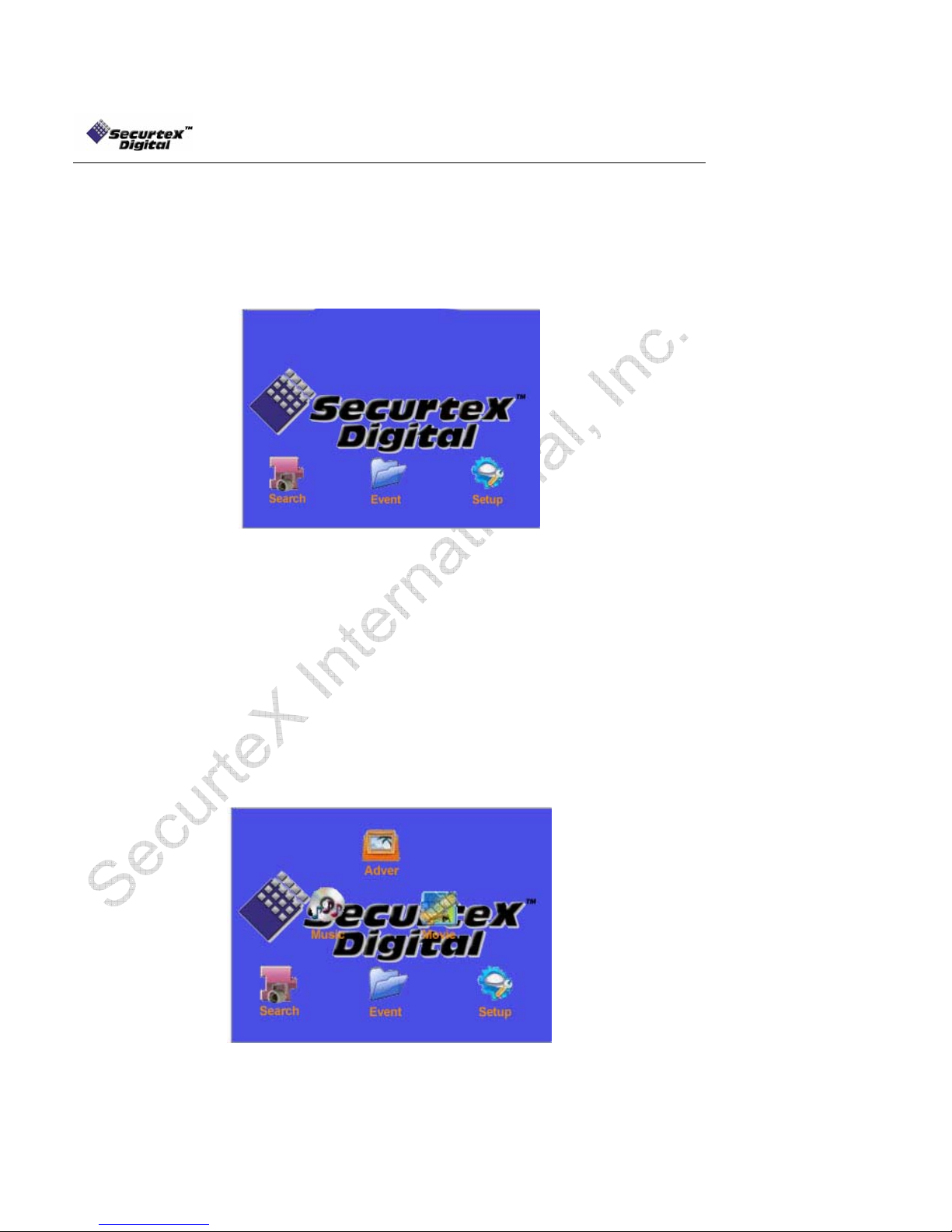
Security only version: In the security only version MDVR has the capability of performing the
Digital Video Recording only. The User Interface is different from Fig 2.0. With the security only
version the User Interface will be as follows:
MDVR comes with the Security only version by factory default. To update the DVR with the Multimedia
version, please consult with your sales associate. There is no hardware update required for the
multimedia features.
Multimedia version: In the multimedia version, MDVR has the capability of performing Digital Video
Recording along with the advertisement, movies and music without interrupting the basic purpose of the
surveillance system. With the multimedia version the User Interface will be same as Fig 2.0
MDVR system layout
Press [SETUP] on the IR controller, if the security is disabled the on-screen menu will be displayed (not
applicable if the output is connected to V 2)
• Navigate through the options using the ARROW keys
• Select the desired option using the ENTER key
• To return to the previous menu from any screen use the EXIT key
Fig 2.0
18
SecurteX MDVR Manual
p
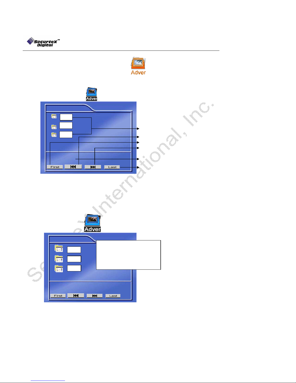
Administer Advertising Files
To administer Advertising files use ARROWS to select and press ENTER
The screen will show the menu as below:
Advertising
Peps
Coke
Nike
Size: 55,952KB
Advertising file
Browse to the previous page
Browse to the first page
Browse to the next page
Displays the advertising file size
Browses to the last page
Play: select the advertising file and press [Enter] to play. While the advertising is playing,
the Handheld IR navigation keys increases / decreases the volume. Press [▌►] will pause
the advertising clips. Pressing the [▌►] key will resume the playback. Press [EXIT] return
to the advertising menu.
Delete the file: Select the file to delete and press the right direction key [►]. The screen will
show a confirmation dialogue as below:
Advertising
Pe
Coke
si
Confirm to delete file (Y/N):
NO
YES
Nike
Size:
Select “NO” and press “ENTER” to cancel the delete operation.
Select “YES” and press “ENTER” to delete the file you have selected. Note that once the file is
deleted it cannot be recovered.
Press [EXIT] to return to the main menu.
19

SecurteX MDVR Manual
Administer Music Files
To administer Music files use ARROWS to select and press ENTER
The screen will show the menu as below:
Music
Take me to your heart
The unforgiving
I love you deeply
Size: 5,735KB
Music file name
Browse to the first page
Browse to the previous page
Browse to the next page
Displays the music file size
Browse to the last page
Select the music file and press [Enter] to start playing the file.
While the music is playing, the Handheld IR navigation keys ((/() increases / decreases the
volume. Pressing [▌►] will pause the music. Pressing the [▌►] key will resume the
playback. Press [EXIT] return to the music menu.
Delete the file: Select the file to delete and press the right direction key [►].
Select “NO” and press “ENTER” to cancel delete operation.
Select “YES” and press “ENTER” to delete the file you have selected. Note that once the
file is deleted it cannot be recovered.
Press [EXIT] to return to the main menu.
20

SecurteX MDVR Manual
Administer Movie Files
To administer Movie files use ARROWS to select and press ENTER
The screen will show the menu as below:
Movi
e
Star wars
Terminator
Austin
Size: 211,750KB
Browse to the previous page
Movie name
Browse to the first page
Show the movie file size
Browse to the last page
Browse to the next page
Select the movie file and press [Enter] to start playing the file.
While the movie is playing, the Handheld IR navigation keys (/) increases /
decreases the volume. Pressing [▌►] will pause the movie. Pressing the [▌►] key will
resume the playback. Press [EXIT] return to the music menu.
Delete the file: Select the file to delete and press the right direction key [►].
Select “NO” and press “ENTER” to cancel delete operation.
Select “YES” and press “ENTER” to delete the file you have selected. Note that once the
file is deleted it cannot be recovered.
Press [EXIT] to return to the main menu.
NOTE: The movies and advertisement contents require the DivX™ codec formatted files. Please
confirm that the uploaded media files are in DivX™ codec for the correct operation. Details of
supported file formats are listed below:
Folder Name
Contents/ Description Remark
Ads
List the contents of the
advertisement files
Supported format:
MPEG4, MPEG2, MPEG1
File extension:
VOB, MPG, AVI, DAT
Movie
List the contents of the movie
files
Supported format:
MPEG4, MPEG2, MPEG1
File extension:
VOB, MPG, AVI, DAT
Music
List the contents of the music
files
Supported format:
WAV
MP3
WMA
Deleted: <sp>
21
SecurteX MDVR Manual
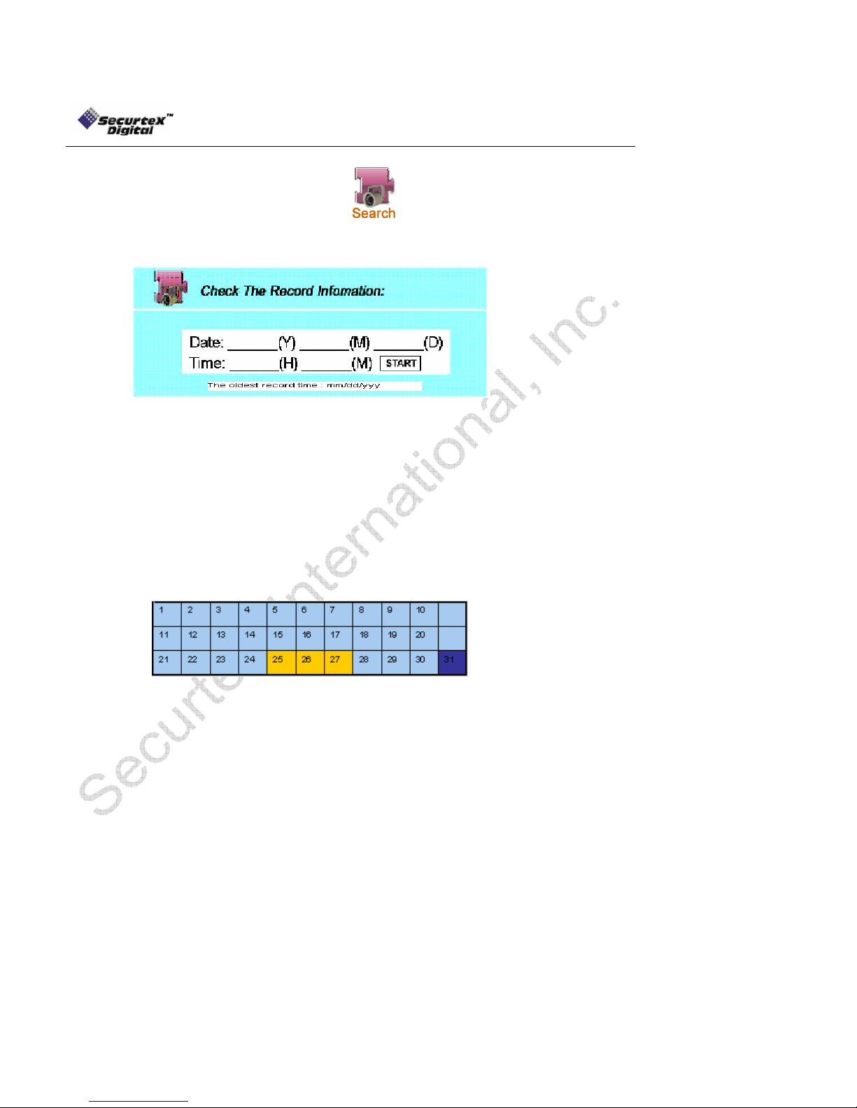
Search the Recordings
To search the recordings use ARROWS to select and press ENTER
Enter the required information on the screen. The MDVR selects the current date by default.
The main screen allows the user to enter the specific dates for the playback. “The oldest record
time” is a quick reference for the oldest recording available to the MDVR. Using the numeric
keypad of the handheld IR controller or [+] [-] keys to increase the values, fill the appropriate data:
“Year”: Range is 2000 to 2099. Only the last 2 digits of the year are changeable
“Month”: Range is 01-12 for the corresponding month number
“Day”: Range 01-31 for the corresponding day of the recording
“Hour”: Range 00-23 for the appropriate hour to begin the search
“Minutes”: Range 00-59 to narrow the search
Press Setup on the hand held IR remote to get the calendar. The yellow color indicates the days
of recording. The blue color indicates no recording.
After entering the start time move to the “START” and press “ENTER” on the handheld IR
controller. The recorded video history beginning at the time chosen will be listed on the screen.
Use the arrow keys to advance to the starting time. Select the entry and press “ENTER” to
playback the video file.
(Ex: “03” for year 2003)
22
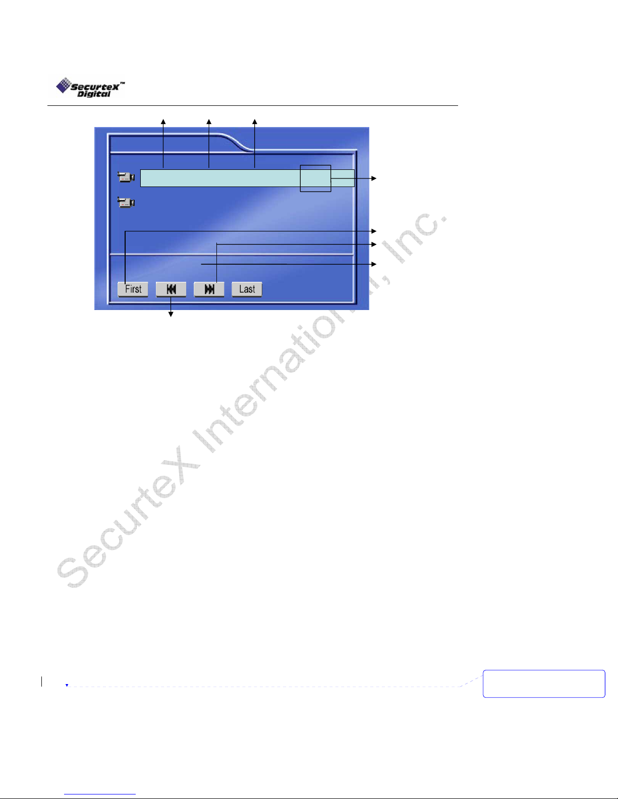
SecurteX MDVR Manual
Date of recording Timing range Number of cameras recorded
Record
09/05/2005
09/05/2005
Size: 1169,686KB
Browse to the last page
02:59-03:00
05:30-06:45
Four Pic 30-1
Four Pic 30-1
Recorded Frame
rates and quality
of video
Browse to the first page
Browse to the next page
Show the movie file size
While the selected video file is playing back, user can select the video to jump to the specific time in
the clip.
Press “Goto” on the handheld and a selection bar would appear at the top left of the screen
with a reference point about the length of the clip.
Input the desired time and select “Start” to go to the required minute.
While the video is playing back, pressing “Enter” on the IR will show the associated text on the
channel and pressing “Enter” again will hide the text giving a clear picture to view. The text on the
video shows the following fields:
Driver ID
Vehicle ID
Camera label
GPS coordinates (if available)
Date
Time
Sensor label (if sensor was activated in the setup and sensor activity happens, the user
definable sensor labels get embedded on the video for 10 seconds)
User can also switch channels of video by pressing the desired number of channel on the handheld
IR numeric Keypad. User can start to download the video on a USB Drive while viewing the playback.
Follow the here under procedure to perform the operation:
Stop the recording of the DVR by going in the setup -> Schedule.
Insert the FAT 32 formatted USB Drive (for the CF formatting instructions please review the
Compact Flash Card Management page in the manual).
Select the clip want to playback.
While viewing the file, press the [CF] key on the IR to start downloading the file on the USB
Drive.
A status indicator is shown on the top right corner of the screen.
Press [CF] key again to stop the download
23
Deleted: 
<sp>
<sp><sp><sp><sp>
SecurteX MDVR Manual
Search for Events
To search for events use ARROWS to select and press ENTER
The screen below will display sensor triggered events. Scroll down the list with the ARROW keys
to find the event you wish to play. After the entry is highlighted press ENTER to play the video.
January
January
January
Number Date Time Sensor Type
2005-01-15
001
002
003
004
003
002
2005-01-16
2005-01-17
2005-01-18
2005-01-19
2005-01-19
14:15:19
14:30:49
14:50:00
15:30:46
15:52:48
18:12:05
Deleted: <sp>
FDOOR
METER
SPEED
REAR
PANIC
DDOOR
Page Down
Page Down
Page Down
Fig 2.1
Page Up
Page Up
Page Up
While the video is playing back, pressing “Enter” on the IR will show the associated text on the
channel and pressing “Enter” again will hide the text giving a clear picture to view. The text on the
video shows the following fields:
Driver ID
Vehicle ID
Camera label
GPS coordinates (if available)
Date
Time
Sensor label (if sensor was activated in the setup and sensor activity happens, the user
definable sensor labels get embedded on the video for 10 seconds)
Once the video associated with the event is finished playing back, the system displays the Fig 2.1 to
select other event.
24

SecurteX MDVR Manual
SETUP Menu
To access the SETUP menu, use ARROWS to select and press ENTER
The SETUP menu consists of five tabs. Each tab is designed to facilitate the performance
adjustments preferred by the user.
1. SYSTEM:
Press ENTER to change system setup information.
• Use ARROW keys on the handheld IR controller to scroll through the list of items on the
• Press ENTER to select the option. The setting area will appear on the right column.
• Press the RIGHT ARROW [
• Press the UP [
• Press the ENTER key to change the value or use the numeric keypad on the handheld
• To save the changes, scroll to APPLY at the bottom screen and press ENTER.
• Press EXIT to quit without saving changes
a)
Date Mode: (US or Int’l) Press ENTER to switch between the date patterns
Record File Size: Press ENTER to scroll through the settings. The
clips in to smaller timings. The available selections
are 15 minutes, 30 minutes, 45 minutes and 60
minutes. Scroll to APPLY and press ENTER to save
the new settings.
Idle Time: Idle time is used to revert back to the live cameras
view if there is no activity from the Handheld IR. The
available options are 10, 20, 30 and 40 seconds.
Press ENTER to browse through the options.
b) Unit ID
c) Video Ty pe
left column.
] key to switch to the data entry area.
] or DOWN [] ARROW key to scroll through the entry fields.
controller for data entry areas where the numeric values are used
Date / Time
Press ENTER to access input settings. Use ARROW keys to scroll through the options.
Date: DD/MM/YYYY Enter with number keys
Time: HH/MM/SS Enter with number keys
Weekend Start: (Day Name) Press ENTER to advance days
Weekend End: (Day Name) Press ENTER to advance days
record file size is used to break down the recording
Use the NUMERIC keypad to enter the unit ID between 000 to 999. This ID is used
when logging in to the unit (if security is enabled). Scroll to APPLY and press ENTER
to save the new settings.
Select the appropriate camera
signal type. Select between
“NTSC” (US) or “PAL”
(International) standards of video
recording. Scroll to APPLY and
press ENTER to save the new
settings.
25

SecurteX MDVR Manual
d) Audible Alarm
Press ENTER to enable or disable alarm buzzer (control panel accessory only). The
buzzer will beep when the following conditions are met:
• External sensor trigger
• Hard disk failure
• Video loss
Note: The audible alarm feature applies to control panel accessory only.
Scroll to APPLY and press ENTER to save the new settings.
e) Priority Record
Press ENTER to enable or disable Priority Record. Priority Recording records one frame every
two seconds when no external sensor is sensed by the unit. When a sensor triggers through a
sensor input, the unit automatically starts to record up to the user selected frames/second on all
cameras. User can select between the timings before and after the event for high frame rate
recording. Use the Numeric key pad or ARROW down to the second settings to define the time
duration of full-rate recording after and before the trigger is over.
Scroll to APPLY and press ENTER to save the new settings.
26

SecurteX MDVR Manual
f) HDD O/W
Press ENTER to switch between “ON” and “OFF”. When the overwrite feature is “ON”
the MDVR will continue the recording. If the HDD is full the oldest data is removed for
the new recording. When the overwrite feature is “OFF” recording will stop when the
HDD is full. You must erase all the recordings using the Setting “HDD Format” to
resume recording.
Scroll to APPLY and press ENTER to save the new settings.
g) HDD Format
There are two options to chose from:
Format HDD: Formats the unit Hard Disk Drive
Format USB Drive: Formats the USB thumb drive
WARNING! Selecting STAR T on this setting will erase all recorded video on the unit
or the data on USB drive, Press ARROW keys to either choose START reformatting
the disk or choose RETURN without formatting. Press ENTER to format or return.
Press EXIT to return to the settings.
27

SecurteX MDVR Manual
h) Network
You must enter a static IP address to use Network capabilities. Please talk to your
local Internet Service Provider for the information. Use NUMERIC keypad to enter the
TCP/IP address information:
Setup “IP address”: Enter the static IP address
Setup “Mask”: Enter the subnet mask
Setup “Gateway”: Enter the gateway
Scroll to APPLY and press ENTER to save the new settings.
i) Security
Selecting “YES” will require a password in order to access the setup menu. Selecting “NO” will
not require a password in order to access the setup menu.
a. An Administrator with full rights and a User with only playback rights can be created.
b. Press ENTER to switch between “YES” and “NO”.
c. Press the down ARROW key to highlight the User password entry line. Enter the desired
password and confirm. The password must be EIGHT NUMBERS long. Use the NUMERIC
keypad on the handheld to input the values.
d. Press the down ARROW key to highlight the administrator password entry line. Enter the
desired password and confirm. The password must be EIGHT NUMBERS long. Use the
NUMERIC keypad on the handheld to input the values.
** The unit has a built in SUPER Password, in
case the ADMINISTRATIVE password does not
work. It is a back door entry to the unit which
cannot be changed. The password is 19810512.
IT IS HIGHLY RECOMMENDED THAT THIS
PASSWORD IS RECORDE D A ND STORED IN A
SAFE PLACE.
28

SecurteX MDVR Manual
j) Default Setup
User ARROW keys to switch between “YES” and “NO”. Selecting YES will restore the
default factory settings.
System Default settings
Options Default Setting
System
Date / Time Current date and time
Weekday Start Monday
Weekday End Friday
Record File Size 60
Idle Time 40
Unit ID 000
Video Type NTSC
Audible Alarm YES
Priority Record Disable
HDD O/W YES
Network
IP Address 192.168.0.100
Subnet Mask 255.255.255.0
Gateway 192.168.0.1
Security Yes
Driver Info
Company Name XYZ
Vehicle Number 123
Driver Name ABC
Camera
Camera 1 Label = No Label Quality = 1 Audio = No
Camera 2 Label = No Label Quality = 1 Audio = No
Camera 3 Label = No Label Quality = 1 Audio = No
Camera 4 Label = No Label Quality = 1 Audio = No
Camera Num 04
Rate (FPS) 30
Resolution CIF
Time Insert ON
Output Mode Adver Autoplay
Schedule Every: 00:00 – 23:59
Event Setup
Sensor 1 Off
Sensor 2 Off
Sensor 3 Off
Sensor 4 Off
Sensor 5 Off
Sensor 6 Off
Sensor 7 Off
Sensor 8 Off
Sensor 9 Off
29

SecurteX MDVR Manual
k) USB Operation
There are two options available with the USB operation.
DEVICE MODE: Using the “ENTER” Key on the handheld IR select the “DEVICE
MODE”. The “DEVICE MODE” allows a computer (or a laptop) to connect to the MDVR
via supplied USB cable. Once connected the drive appears as a regular hard drive in
the computer. Normal Window operations could be performed (example: Download the
recorded data from the unit to the computer hard drive, Upload the advertisement clips
from the computer to the unit etc). For a complete file description of the MDVR hard
drive layout please look at the chapter labeled as ”Hard Disk File Structure” towards the
end of the manual.
HOST MODE: Using the “ENTER” Key on the handheld IR, select the “HOST MODE”.
The “HOST MODE” allows an external USB jump drive to be connected. Once the
connection is established, all the contents of the jump drive is automatically uploaded to
the MDVR “ads” folder. For a complete file description of the MDVR hard drive layout
please look at the chapter labeled as ”Hard Disk File Structure” at the end of the
manual.
NOTE for USB Operation: To maintain the live connection between Windows PC and MDVR via USB
cable, the Device Mode menu screen needs to stay active. Exiting the option will interrupt the
connection.
30

SecurteX MDVR Manual
l) Driver Info
The “DRIVER INFO” is used to store the following text information into the unit:
Company Name, Vehicle Number, and Driver Name. Use ARROW keys to select
the option for modification. Press ENTER at the highlighted line.
The screen will pop up a text entry keyboard. Use Arrows to choose characters, press ENTER to type. Press
APPLY and EXIT to return to the previous menu.
Press EXIT to return to the SETUP list.
Press the RIGHT ARROW key to change control to the CAMERA tab. Press ENTER to open the Camera
configuration screen.
31
SecurteX MDVR Manual
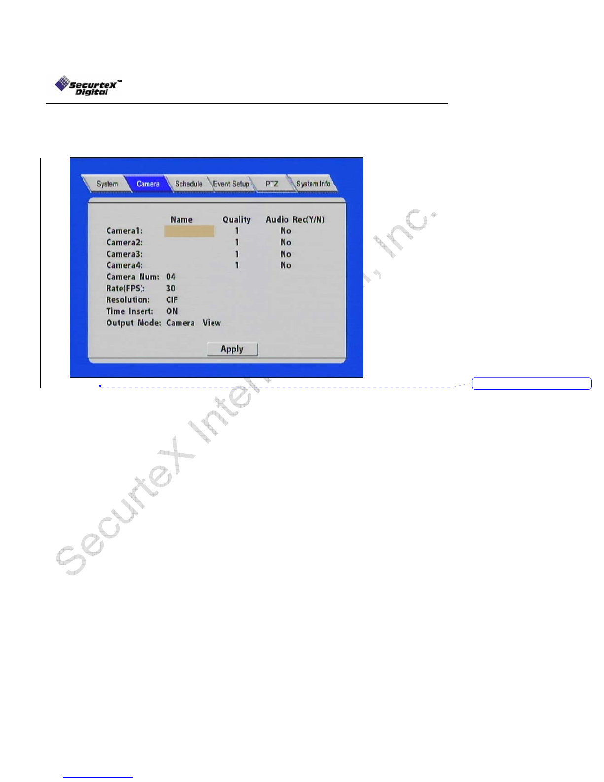
Camera Menu
Press ARROW keys to move to each highlighted field and press ENTER to type into each field highlighted.
Camera Name: Type in the title for each camera to appear on the video display.
The camera label is embedded on the video (8 letters max)
Image Quality: Press ENTER to enter the recording quality (1 is the highest
quality)
Audio Rec: Enable / Disable for the audio record for each camera channel
Camera Num: Press ENTER to choose the number of cameras connected. If 01
is selected channel 1 would be enabled. If 02 is selected
channels 1 and 2 will be enabled. If 03 is selected channels 1, 2
and 3 will be enabled. If 04 is selected channels 1, 2, 3 and 4 will
be enabled.
Recording Rate: Press ENTER to choose between:
Resolution: Select between CIF and HD1
Time Insert: Press ENTER to switch between “ON” and “OFF” to embed time/date
in the video
Output Mode: The MDVR is capable of displaying multimedia advertising when
the unit is powered on. User can select the option of
displaying live cameras (Camera View) on the monitor or
automatically start streaming the advertising clips (Adver Autoplay).
Press ENTER to select between “Camera View” or “Adver Autoplay”
mode.
Scroll to APPLY and press ENTER to save the new settings.
Press the RIGHT ARROW key to move to the Schedule tab and press ENTER.
2, 4, 8, 15, or 30 frames/second (for NTSC)
1, 3, 6, 12, or 25 frames/second (for PAL)
Deleted: <sp>
32
SecurteX MDVR Manual
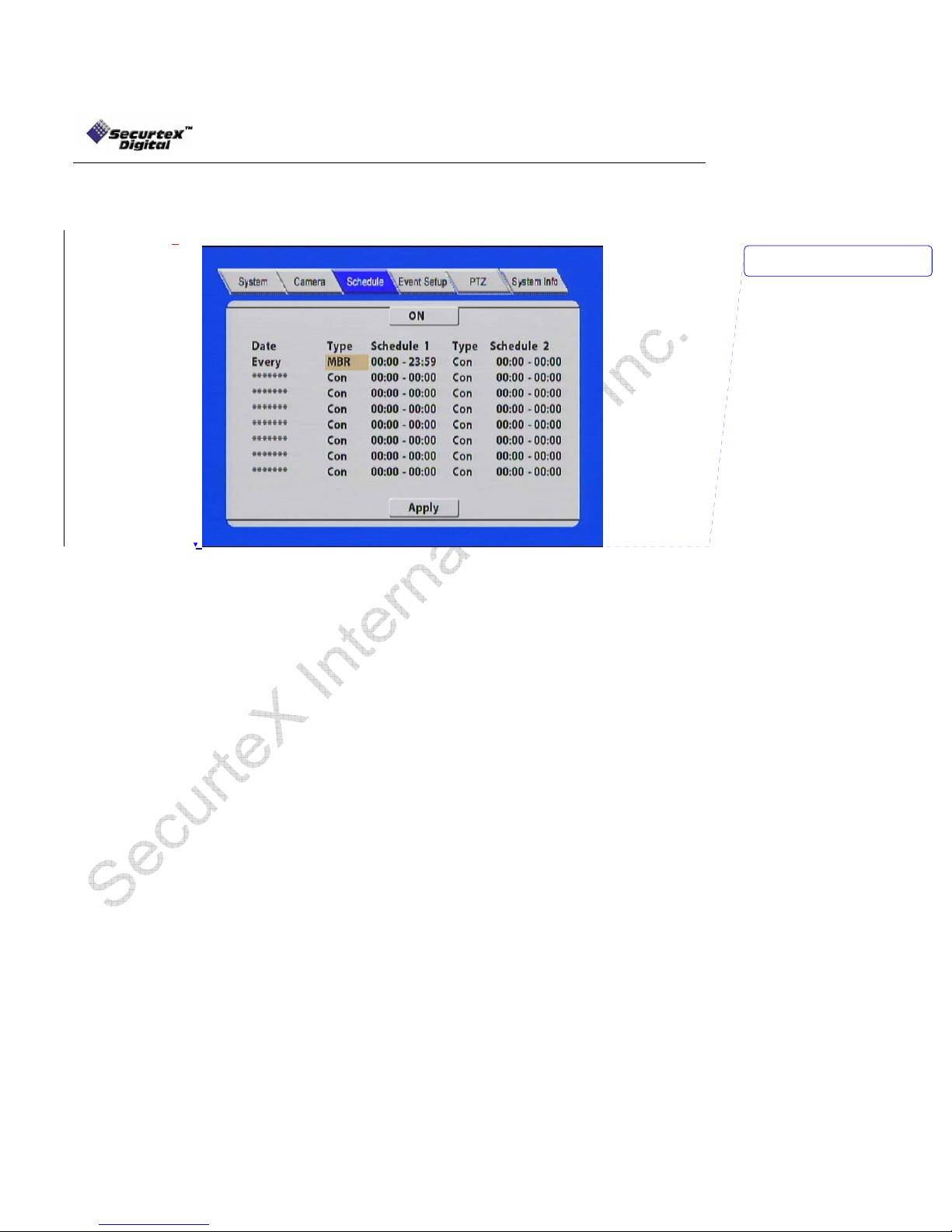
Recording Schedule
Press ENTER to activate (ON) recording schedule.
Press the ARROW keys to change between any fields in the menu.
Date: Press ENTER to change the period of time to control the recording schedule
Single Day: Choose the name of a day to create a recording schedule
Every: Choose “Every” to apply a schedule to every day of the week
Weekday: Schedule will only apply Weekdays (weekday start and weekday
end can be defined in the SYSTEM tab)
**********: Choosing the asterisks will suspend the highlighted schedule
Schedule #: Press the RIGHT ARROW key to enter values using the NUMERIC keypad into
any time field. Schedule 1 is the first of two possible ON/OFF cycles that apply to
any day in the period chosen under Date. Schedule 2 is the second cycle for any
day in the period. There is no need to overlap times of Schedule 1 and Schedule
2. Ending at 23:59 of one day and beginning with 00:00 of the next day will
provide continuous recording without interruption (factory default setting)
Scroll to APPLY and press ENTER to save the new settings.
Press EXIT at any time to discard your entries and return to the previous menu.
Types:
CON = constant recording
MBR = motion based recording
SEN = sensor triggered recording
S/M = sensor triggered recording / motion based recording together
Deleted:
<sp>
33
SecurteX MDVR Manual
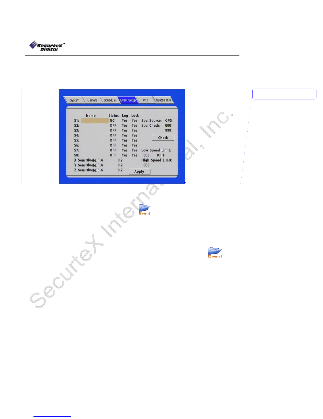
Sensor Menu
Choose the EVENT tab and press enter to access the following menu. The Event menu identifies sensor
inputs by name and selects them for use.
Deleted:
<sp>
Name: Press ENTER on the Name field to display the virtual keyboard. Enter the text name
NC/NO/OFF: Press ENTER to turn Normal Close (NC), Normal Open (NO) or turn OFF an
input sensor.
P.Record: P. Record is the priority recording mode. User can select which external sensor
input will trigger high frame recording. Press ENTER to select between “YES or
Low Speed Limit: If the vehicle exceeds the low speed limit, MDVR will start an audible alarm until the
High Speed Limit: If the vehicle exceeds the high speed limit, MDVR will trigger the alarm signal (ALM
LED turn on) until the Admin password is entered to acknowledge the alarm.
SPD Source: MDVR is capable of capturing vehicle speed via GPS antenna or
SPD Check: Speak check is used to calibrate the offset speed when connected to the
to identify the source of each Sensor connected to the unit. The sensor label embeds
with the video when the sensor is triggered. The label also identifies the type of event
when doing a quick search using
NO”. If NO is selected, the MDVR will continue to record at 1 frame per 2 seconds
even when the sensor triggers. The sensor entry will be made in the
option without jumping to the high frame recording.
vehicle slows down the limit.
speedometer. Browse between the settings of GPS or speedometer from the list.
Please note that the GPS antenna should be connected to the MDVR to receive
satellite signals for speed. For more information on capturing speed from
speedometer please contact manufacturer.
speedometer. For more information on capturing speed from the speedometer please
contact the manufacturer.
option.
34
SecurteX MDVR Manual
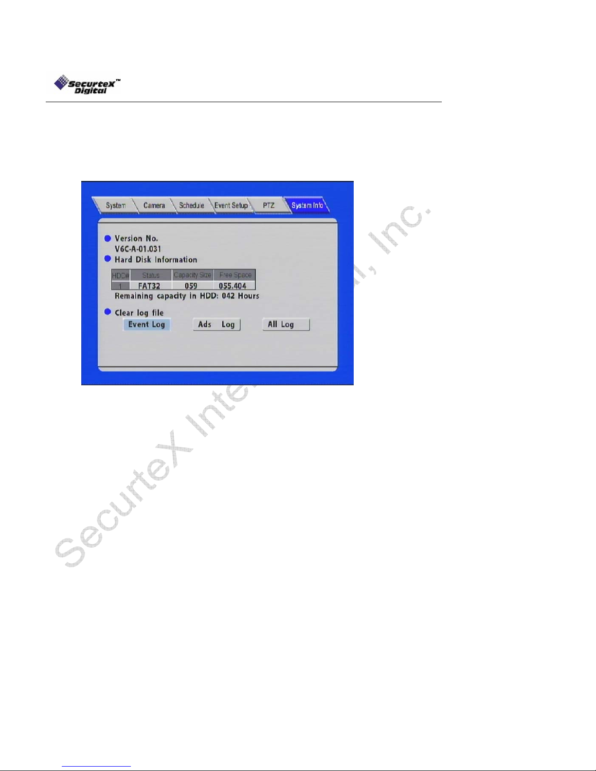
System Information
Press ENTER to assess the System Information menu.
This menu displays DVR Information that may be required for technical support.
In addition, information regarding the installed hard disk also displayed. In this menu, user can clear the log
information of the DVR.
Clear [Event Log]/ [Ads Log]:
select this option and press [Enter], the DVR will prompt a confirmation
message. Select [YES] and press [Enter]. This will clear the log file
from the unit. Select [NO] to cancel to clear the log file.
[All Logs]: select this option to clear both [Event Log] and [Advert Log] file
simultaneously.
WARNING! ! The log entries in the EVENT are also a part of the log file. Deleting the Ev ent log
file will also delete the entries in the EVENT.
35

SecurteX MDVR Manual
System Firmware Upgrade Procedure
There are 2 methods to upgrade the firmware in the MDVR:
Hard Disk upgrade Instructions
a) Connect and Enable the USB
b) Copy the romfs.dvr file by pressing ctrl + c or going to Edit -> Copy
c) Open the ADS folder on the MDVR HDD (if there is no folder by the name create a new folder by
right clicking on the mouse and choosing new -> folder)
d) Paste the file in the “ADS” folder by pressing ctrl + v or going to Edit -> Paste
e) Close the connection by double clicking the “unplug or eject hardware” icon in the system tray.
Select the USB Mass Storage Device and click Stop
f) Restart the unit. The system will start to upgrade automatically
g) During the upgrade [POW] and [ALM] LEDs will start to flash
h) Once completed the upgrade file will be deleted from the ads folder automatically
USB Drive upgrade Instructions
USB Thumb Drive can also be used to update the firmware in the unit. Please follow the
instructions to update the flash using the USB drive:
a) Insert a USB drive into the USB slot of your Windows PC (Drive letter appears)
b) Using Windows Explorer, format the USB drive as FAT32 format. All the data will be permanently
erased from the USB drive.
c) Copy the new firmware (romfs.dvr file) on the USB drive
Remove the USB Drive from the PC and insert it into the slot on your MDVR while the power is off.
d) Upon turning the power on, the unit will automatically start to update the new firmware from the USB
drive. During the upgrade [POW] and [ALM] LEDs will start to flash
e) Remove the USB drive from the Mobile unit once unit is up and running.
WARNING: The upgrade procedure requires no power interruption. The US B drive slot on the unit is
a necessary opening on the unit. Please ensure that no liquid is spilled in the slot. I n addition, do not
install the system where dust and dirt are likely to contaminate the opening.
36
SecurteX MDVR Manual
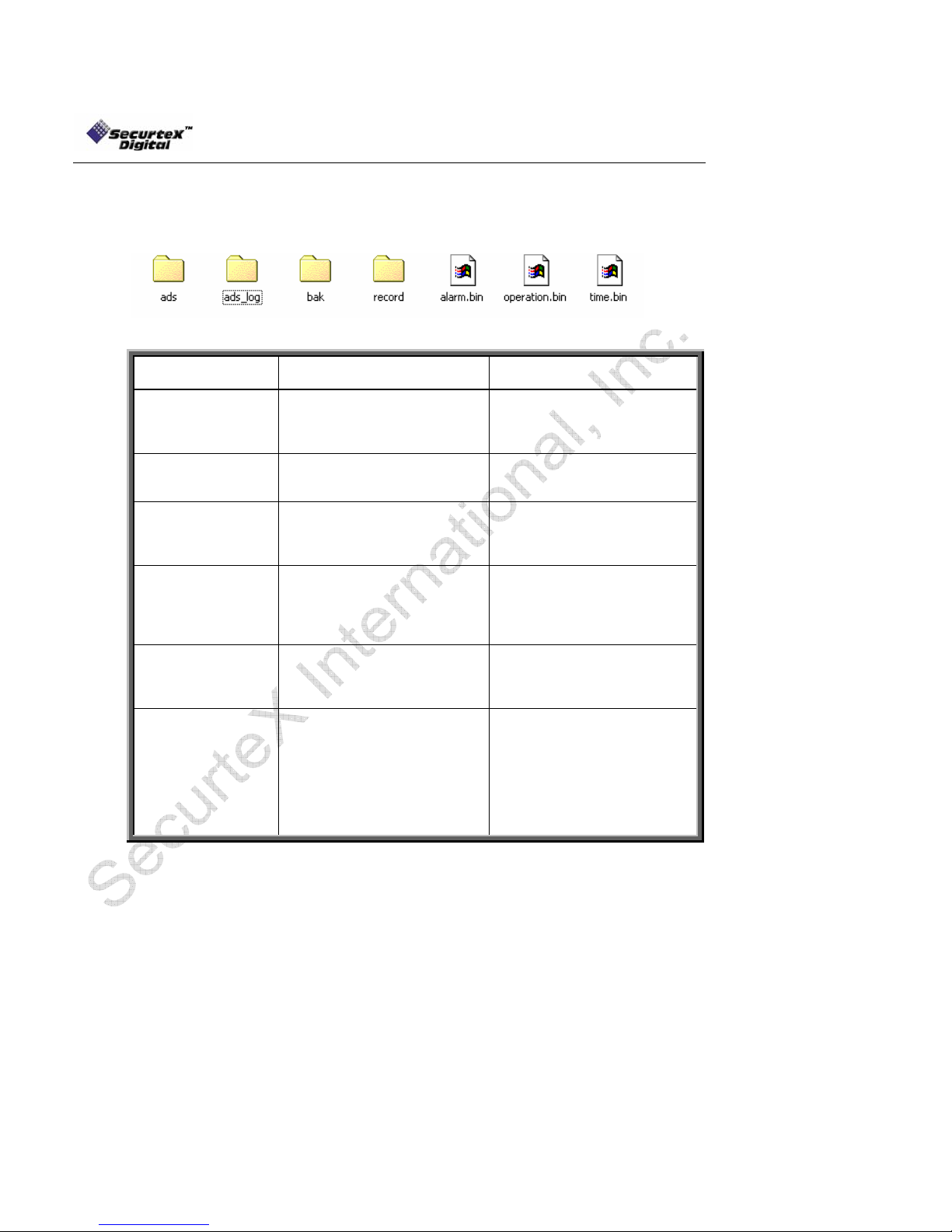
Hard Disk File Structure
Hard Disk file structure: Using the USB to connect the DVR to PC the file structure of the unit looks like
below:
Folder Name
Ads
Ads_log
Movie
Music
Record
Time.bin, Alarm.bin,
Operation.bin
Contents/ Description Remark
Contains advertisement files Supported format:
MPEG4, MPEG2, MPEG1
File extension :
VOB, MPG, AVI, DAT
Log file for tracking all the
advertisement playback history
by MDVR
Contains movie files Supported format:
Contains music files Supported format:
Contains DVR recordings Requires client software to
System files
Use log viewer application to
open this file (provided by
SecurteX)
MPEG4, MPEG2, MPEG1
File extension :
VOB, MPG, AVI, DAT
WAV
MP3
WMA
playback video from PC.
All the record file are
watermarked for authenticity
DO NOT DELETE THE FILES.
THESE ARE NECCESSARY
FILES NEEDED BY THE
SYSTEM TO FUNCTION
PROPERLY
37

SecurteX MDVR Manual
GPS Operation (Optional)
This feature is only available with the system ordered with GPS
1. To enable the feature make sure to connect the GPS antenna to the GPS connection port located at the
back of docking station.
2. Once connected properly and placed outside the vehicle facing towards the sky, you will find the GPS
icon display on the surveillance screen as shown:
3. The GPS data will appear on the screen as:
• N for longitude
• W for latitude
• Vehicle Seed
4. The values of GPS are embedded on the video and could be retrieved by using the video playback
function and pressing Enter key on the hand held while the video is been played back.
38
SecurteX MDVR Manual
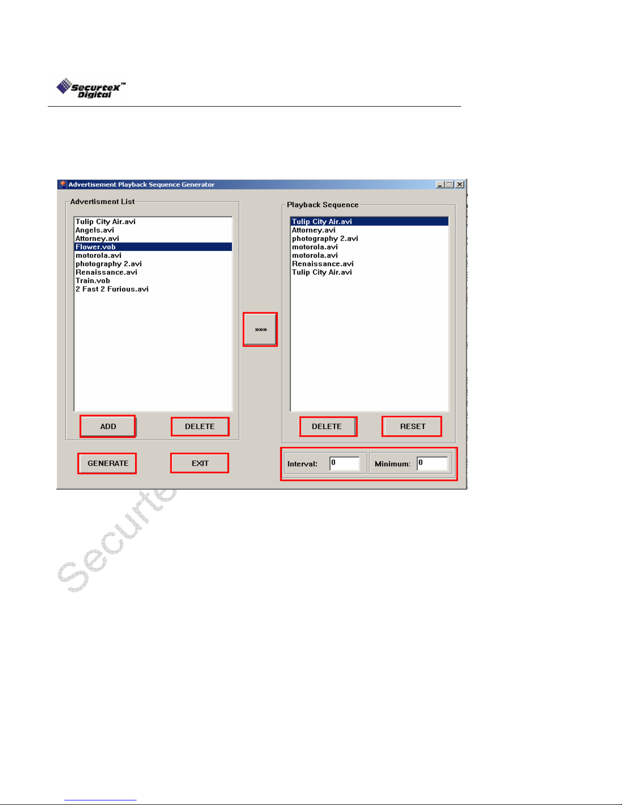
Advertisement Sequence Generator (Optional)
This utility only applies to the multimedia version of MDVR
1
3
4
5
8
6
FIG 3.0
The Advertisement Playback Sequence Generator is a Windows based utility designed to generate sequence
for the advertisement playback. The utility creates a sequence configuration file which maintains the pattern of
advertisement playback. Follow the here under instructions for generating the advertising sequence.
Note: In the above example after photography 2.avi is played back the Motorola.avi will be played twice
before the Renaissance.avi is played back. Use the repetition method to playback same clip more then once.
1) Click “ADD” button to add the advertisement clips. Browse for the advertisement content
location and select the desired file. To select multiple files hold down the “CTRL” key on
your keyboard and select desired files. The application only accepts AVI, MPG, VOB, DAT
file formats.
2) Once the files are added to the “Advertisement List”, select the first file to be played back in
the advertisement sequence and use (2) button to move the file in the “Playback
Sequence.” The advertisement clips will be played in the order that appear in the “Playback
Sequence list”. When the last advertising clip is played back, the sequence starts again.
39

SecurteX MDVR Manual
3) To remove any advertisement from the “Advertisement List”, select the file and click
“DELETE” button. Note that deleting the file from the “Advertisement List” does not delete
the actual file from the hard disk.
4) To remove any advertisement from the “Playback Sequence”, select the file and click
“DELETE” button. Note that deleting the file from the “Playback Sequence” does not delete
the actual file from the hard disk.
5) To delete the sequence and start from beginning click the “RESET” button.
6) When the sequence is completed click on “GENERATE” to generate the configuration file.
A “Save as” window will appear at the screen to save the sequence file. For the MDVR to
play back in the correct sequence the file name has to be “advertisement” and the format
has to be “.cfg”. DO NOT CHANGE THE NAME OR TYPE OF THE FILE ELSE THE
SEQUENCE OF THE ADVERTISMENT CLIPS WILL NOT WORK.
7) This feature is under development.
8) To exit the sequence generator application click on “EXIT”.
There are two methods to upload the sequence configuration file on the MDVR.
1) When the advertisement.cfg file is created save it to the thumb drive along with the required
advertisement contents. Establish a USB connection in Host Mode with your MDVR. Follow the
instructions under SETUP -> USB OPERATION for more details on establishing the USB connection
in Host Mode. The files would automatically be copied upon successful connection with thumb drive.
Once the data is copied (indicated by the status bar) exit the USB MODE screen and the advertising
media contents would automatically start to play back in the programmed sequence (if advertisement
mode selected under CAMERA -> OUTPUT MODE) when the unit restarts.
2) Create a USB connection using the USB cable provided with your MDVR package. For detailed
instructions on the USB connectivity refer to SETUP -> USB OPERATION in DEVICE MODE. Save
the advertisement.cfg file in the “ADS” folder of MDVR Hard disk drive. Also copy the media clips in
the ADS folder. Exit the USB MODE screen and the advertising media contents would automatically
start to play back in the programmed sequence (if advertisement mode selected under CAMERA ->
OUTPUT MODE) when the unit restarts.
Note that this application only generates the sequence and does not upload/download the media contents
automatically. Users have to upload the advertising contents by either a USB Drive or a USB link (HOST or
DEVICE mode).
40

SecurteX MDVR Manual
Advertisement Log Viewer (Optional)
This utility only applies to the multimedia version of MDVR
FIG 4.0
The Advertisement log viewer is a Windows based utility designed to read the log of the advertisement clips
played back. The utility allows the user to see the frequency of the advertisement clips MDVR played back.
Follow the here under instructions for reviewing the frequency of clips played back by MDVR.
1) Create a USB connection using the USB cable provided with your MDVR package. For detailed
instructions on the USB connectivity refer to SETUP -> USB OPERATION in DEVICE MODE.
FIG 4.1
2) The MDVR hard drive comes up as a new hard drive on the workstation connected via USB Cable.
FIG 4.1 shows the contents of MDVR hard drive. Copy the ads_log folder by pressing ctrl + c or going to
Edit -> Copy. Paste the folder to your workstation by pressing ctrl + v or going to Edit -> Paste. Once
completed press “Exit” on the MDVR hand held IR. The MDVR will restart to resume normal operation.
41

SecurteX MDVR Manual
FIG 4.2
3) Open the advertisement log viewer application by double clicking on ads_log_viewer.exe. Right click
on “FILE LIST” and a drop down menu will be displayed as shown in FIG 4.2. Select “add file” option and
browse for the “ads_log” folder. Select the desired advertisement clip to perform the analysis (the files
would have the extension of .raw) . To select multiple files hold on the ctrl key and left click on the files.
Once the files are selected click on “Open”.
FIG 4.3
4) Click on the desired files to see their frequency of play back. The application displays year, month,
day, hour and minutes when the advertisement clips were played back by MDVR. A sample report is
shown in FIG 4.3. Once completed, click “EXIT” to quit the application.
42

SecurteX MDVR Manual
Setup Manager (Optional)
This utility is designed to change the MDVR setup without using the IR Hand held via USB Drive.
1
2
3
Fig 5.0
The Setup Manager is a Windows based utility designed to program the MDVR from the PC without using
handheld IR via USB Drive. Follow the here under instructions for MDVR settings using a USB Drive.
1) Setup -> Allows user to go in the setup and create a new setup (binary) file to be uploaded to the
MDVR via USB Drive
2) Modify -> Allows user to change an existence setup (binary) file
3) Display -> Allows user to view an existence setup (binary) file
4) Exit -> Exits the application
SETUP:
FIG 5.1
43

SecurteX MDVR Manual
The Setup allows user to create a user preferable settings for MDVR. FIG 5.1 shows the user interface for
creating the setup file to be applied on the MDVR via a USB Drive. System, Camera, Schedule, Event and
Network tab allows making changes as per user desire. The explanation of each individual tab could be found
under MDVR System Layout, section (f) of the manual.
FIG 5.2
Once the changes has been completed click on the “SAVE” button on FIG 5.1. A save as window will come up
on the screen (FIG 5.2). Connect the USB Drive to the workstation which is running the Setup Manager utility.
The USB Drive appears as a removable disk in most of the system. Please check the manual provided with
the USB Drive if your USB Drive does not appear as a removable disk. Format the USB Drive using FAT32
format. For detailed instructions on formatting the USB Drive please consult the “System Firmware Upgrade
Procedure“ in this manual. Select the removable disk from the list of available drives. Click on “SAVE” option
on the screen. DO NOT CHANGE THE NAME AND TYPE OF THE FILE. MDVR ONLY ACCEPTS setup.bin
FOR THE NEW CHANGES. Save the file as the default type and name.
44

MODIFY:
SecurteX MDVR Manual
FIG 5.3
The modify option allows user to edit an existing setup.bin file. Click on MODIFY in FIG 5.0 to modify an
existing setup. FIG 5.3 shows the user interface of the application. Click on OPEN to open the setup.bin file.
Once opened, user can make any changes desired. When the changes are completed save the setup.bin file
on the USB Drive and apply the new settings on the MDVR.
DISPLAY:
The display feature allows the user to see the contents of the setup.bin file. It does not allow the user to make
changes or create a new setup.bin file.
EXIT:
The exit option allows the user to exit the application. A confirmation message will be displayed.
Click Yes to exit the application or no to return back to the Setup Manager application.
45

SecurteX MDVR Manual
SecurteX Digital
982 Senate Drive
Dayton, OH 45459
Phone: 937-312-1414
Fax: 937-312-1418
http://www.securtex.com
46
 Loading...