

Page 1
INSTALLATION MANUAL©
ST-PTZMINI-IR10X
High-Speed Intelligent Dome
Software-Addressable
IR PTZ Color Camera
1
Page 2

Copyright North American Cable Equipment, Inc.
PACKAGE CONTENTS
This package contains:
One ST-PTZMINI-IR10X high-speed intelligent dome color camera.
One mounting bracket.
One 24VAC 2A power supply.
One installation manual.
PRODUCT DESCRIPTION
The ST-PTZMINI-IR10X is a professional grade infrared intelligent dome color camera with pan, tilt and zoom (PTZ)
capability and 650TVL resolution. The camera’s non-volatile digital memory allows the saving of all settings in the event
of power loss. Its 220 preset positions provide versatility for cruise routes and tour functions. The ST-PTZMINI-IR10X’s
mechanical design permits continuous horizontal 360 rotation and 90 vertical flip. Temperature management is built-in.
Functions and Features
PWM function - Intelligent IR illumination & power consumption is variable, dependent on the zoom factor.
3D allocation – Pan, Tilt and Zoom are all performed simultaneously for faster preset recall.
Supported Protocols - Pelco-D/P
4 patterns - Each pattern can record 512 different PTZ instructions or roughly 600 seconds of PTZ path
operation.
Proportional control speed – When zoomed to full telephoto mode, a low pan speed of 0.02°/s provides smooth
panning.
4 Tour groups. The dwell time and position of 16 preset points per tour can be edited independently.
Built-in high precision real-time clock supports time management functions.
Park action - If the dome sits idle for a predetermined amount of time, it will automatically run a tour, pattern, L/R
scan etc.
The camera remembers the last function before powering off, and resumes it when powered back on.
Built-in fan and heater can control the temperature automatically.
Heater engages below 32° F and fan engages above 104° F.
Multiple languages for OSD menu, English, Spanish, Italian, French, German.
Ratio of illumination to ambient light can be adjusted.
Accurate step motor control makes it stable to operate and provides precise location and response.
Chassis construction is all metal, with an IP 66 environmental rating.
Built-in 6000V lighting and surge protection equipment.
2
Page 3

IMPORTANT SAFEGUARDS
1. Read these instructions before attempting installation or operation of dome device.
2. Keep these instructions for future reference.
3. Heed all warnings and adhere to electrical specifications. Follow all instructions.
4. Clean only with nonabrasive dry cotton cloth, lint free and approved acrylic cleaners.
5. Should the lens of the camera become dirty, use special lens cleaning cloth and solution to properl y clean it.
6. Do not block any ventilation openings. Install in accordance with manufacturer’s instructions.
7. Use only attachments or accessories specified by the manufacturer.
8. Verify that the surface you are planning to use for attaching the dome can adequately support the weight of the
device and mounting hardware.
9. Protect this device against lighting storms with proper power supplies.
10. Refer all servicing to qualified service personnel. Servicing is required when the device has been damaged in
any way, when liquid traces are present, or the presence of loose objects is evident or if the device does not
function properl y, or has received sever impact or has been dropped accidentally.
11. Do not use this product under circumstances exceeding specified temperature and humidity ratings.
12. Avoid pointing the camera directly to the sun or other extremely bright objects for prolonged period of time
avoiding the risk of permanent damages to the imaging sensor.
13. The attached instructions are for use by qualified personnel only. To reduce the risks of electric shock, do not
perform any servicing other than contained in the operating instructions unless you are qualified to do so.
14. During usage, user should abide by all electrical safety standards and adhere to electrical specifications for the
operation of the dome. The control cable for RS485 communications as well as the video signal cables should be
isolated from high voltage equipment and high voltage cables.
15. Use supplied power supply transformer only.
3
Page 4

Specificati
Horizontal Rotation Speed 0.02°
-200°/s
Tilt Rotation Speed
0.02°-120°/s
Horizontal Rotation Range
360
°
Tilt Rotation Range
93
°
Auto Flip
Horizontal 180°, Vertical 93°
Zoom-proportional Speed Suppor
t
Auto control IR LED
PWM
IR Testing Time
2-15s selectable
Ambient Light Reporting
0-50
grades
IR Illumination On
0-25 grades selectable
IR Output Power
1-9 grades selectable
IR Standby Power
1-9 grades selectable
IR Standby Time
2-15s selectable
A-B Scan
User
programmable
A-B Scan Speed
1-9 speed setting available
360° Scan Speed
1-9 speed setting available
Dwell Preset
5-60s int
erva
l
Preset Points
220
Go to Preset Speed
200°/s
Programmable Tours
4
groups
Points Per Tour
Max.16 points, dwell time user selectable
Pattern Scan
4
Pattern Scan Record
max. 512 commands (Roughly 10 minutes)
Park Time
1-60 minutes
PWR on Action
Memory/Pattern/Tour/360° scan/A-B scan/Preset 1-8/None
Park Action
Pattern/Tour/360° scan/A-B scan/Preset 1-8/None
Communication Protocol
Pelco-D, Pel
co-
P
Communication
RS485 Bus
Baud Rate
1200/2400/4800/9600bps
Camera ID (soft ID
1-255
Remote Upgrade
Supported via
OSD Menu
Multiple
Language
Time Scheduling function
8 t
asks
Operating Temperature
-40°F ~ +140°F
Operating humidity
≤95% Non-condensing
Heater & Blower
Auto temperature control
Power
24VAC 2A
Lightning protection
Transient voltage up to 6000V
IR Illumination Distance
165ft
Power Consumption
≤ 15W
Environmental rating
IP66
ons
4
Page 5
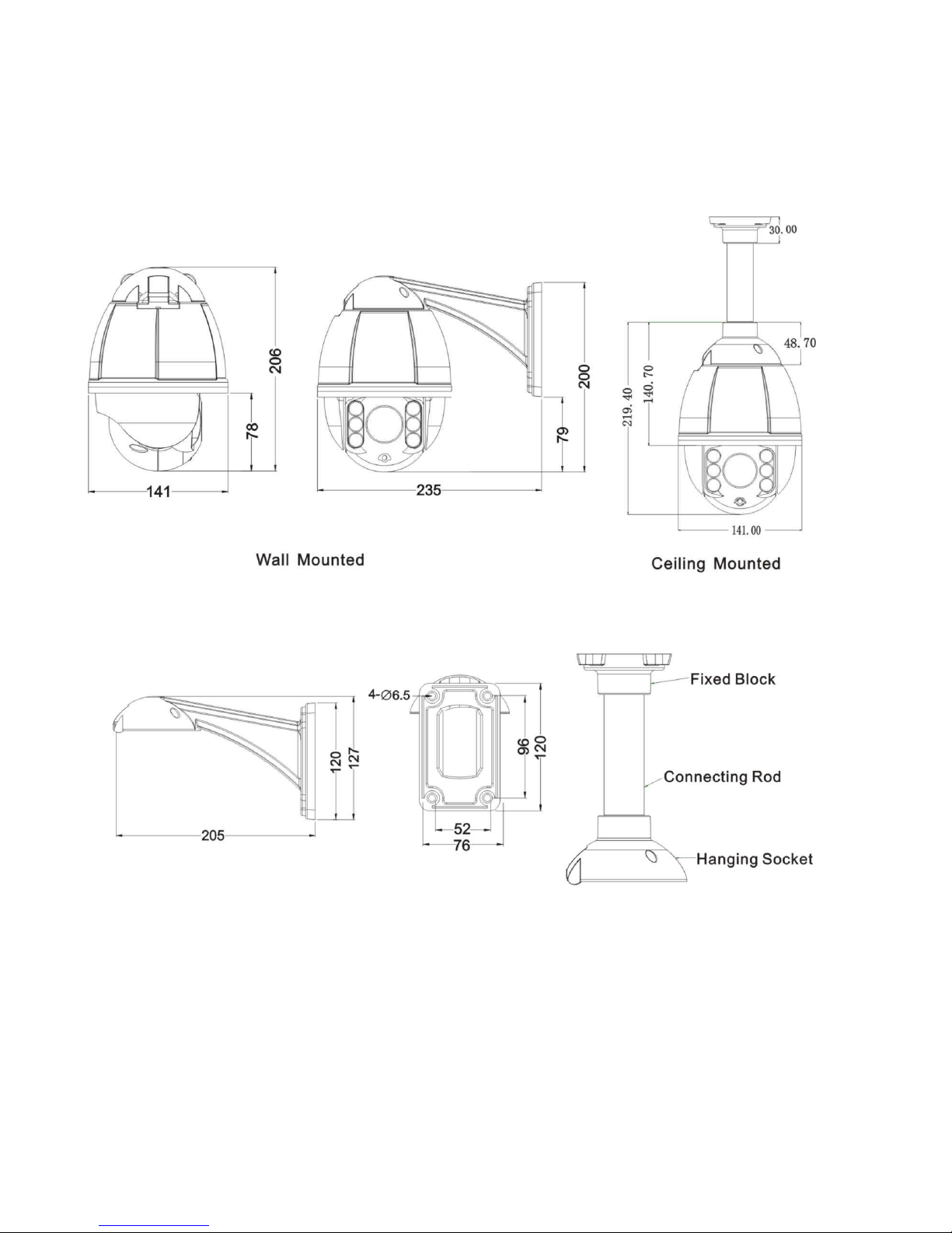
Included Wall Mount Bracket Optional Ceiling Mount Bracket
Product Dimensions (in millimeters)
Bracket Dimensions
5
Page 6
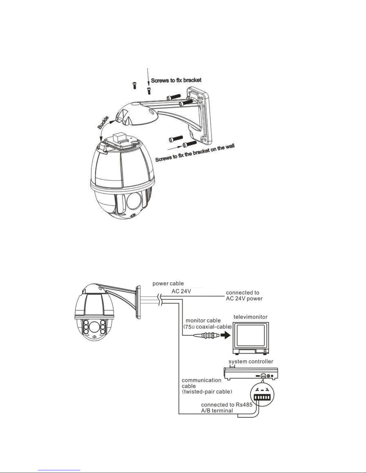
Installation
C
onnecti
Before connecting, please turn off the power of all connected devices. Use the included power supply to ensure the
camera is being supplied sufficient current for proper operation.
ons
6
Page 7

Instructi
IR SPEED DOME
PROTOCOL PELCO-D/P
COMM
2400.N.8.1
DOME ID 001
MODULE
VERSION V1.2
PAN INIT
TILT INIT
POWER O
N
IR SPEED DOME
PROTOCOL PELCO-D/P
COMM
2400.N.8.1
DOME ID 001
MODULE
VERSION V1.2
PAN INIT
TILT INIT
POWER O
N
IR SPEED DOME
PROTOCOL PELCO-D/P
COMM
2400.N.8.1
DOME ID 001
MODULE ST-370
VERSION V1.2
PAN INIT
TILT INIT
POWER O
N
Power On Action
ons
When initializing the system, the display shown at left will appear roughly 5
seconds after powering the camera.
When restoring the original factory settings it will take roughly 1 minute for
the camera to restore all settings and reboot.
This display indicates that the camera is initializing the pan and tilt
motors.
The initialization of pan and tilt motors is now complete. The camera is now
initializing and detecting the module of camera.
.
The display now indicates that “ST-370” is the specific model of camera
module which is installed. This is displayed after the
Self testing is now complete.
camera
finishes detection.
7
Page 8

Basic Function
PRESET
FUNCTION
PRESET
FUNCTION
33
Pan 180 º from current position
85
Force on NEAR light
34
Reset Camera
91
Start A-B Scan (Left-Right Scan)
75
Call Pattern 1
92
Set left point of A-B scan
76
Call Pattern 2
93
Set right point of A-B scan
77
Call Pattern 3
94
Close OSD menu
78
Call Pattern 4
95
View OSD menu
81
Set Day/Night to AUTO
96
Call Tour 3
82
Switch to night
97
Call Tour 2
83
Switch to day
98
Call Tour 1
84
Force on FAR light
99
Begin 360° scan
Controlling the dome’s position (PTZ)
The dome responds to standard PTZ controls UP, DOWN, LEFT, RIGHT and ZOOM to position the
camera toward a subject to observe. The camera supports PROPORTIONAL ZOOM which will cause
the pan and tilt functions to operate at lower speeds when the camera is zoomed to the maximum setting
(10X optical zoom). Proportional zoom can be disabled in the OSD menu if desired.
Zoom
The camera provides 10X optical zoom magnification to aid in viewing objects which are further away
from the camera. Use the controller’s ‘ZOOM TELE’ or ‘ZOOM +’ or similar to increase the increase
image magnification. Use the controller’s ‘ZOOM WIDE’ or ‘ZOOM -’ or similar to decrease image
magnification for a wider image area.
Focus
The camera supports both AUTO - FOCUS and MANUAL - FOCUS functions. The default is AUTO
focus. Operating the controller’s FOCUS NEAR and FOCUS FAR controls will temporarily override
the AUTO FOCUS function. As soon as any PTZ command is received, the camera will revert back to
AUTO-FOCUS.
Preset Point
This camera will respond to all standard Pelco preset commands. Please refer to your PTZ
controller or DVR instruction manual for specific instructions regarding how to set, call and clear
preset points.
NOTE:
Special Functi
The follow presets are predefined for special functions. Use your controller’s “Call Preset” procedure
to perform these functions:
Some preset points are reserved for special functions, as noted below.
on Presets
8
Page 9

General OSD Operation
Call preset 95 to enter the OSD, call preset 94 to exit the OSD.
Up or Down: Move the cursor UP and DOWN within the OSD, change the value on the
OSD.
Right: Enter the option, select the item or confirm.
Left: Return to main menu or cancel.
Zoom Display: This displays the current zoom of the camera.
Time Display: This displays the current Date and Time of the camera’s internal clock.
Angle Display: This displays the current coordinates of the camera’
IR Display: ☀means the IR display status is on. means the IR is on.
Remark:
some
“-”means the cursor selecting some option. “ ” means editing the content of
options.
NOTE:
The default communication settings for this camera are BAUD = 2400,
ADDRESS = 1 and PROTOCOL = PELCO D.
CAUTION:
THERE ARE NO DIP SWITCHES IN THE CAMERA. DO NOT OPEN
THE CAMERA CASING FOR ANY REASON. DOING SO WILL VOID
THE WARRANTY. THE ONLY WAY TO SET THE ADDRESS AND
BAUD RATE SETTINGS IS BY USING THE OSD MENU.
From the MAIN MENU, enter the SYSTEM MENU, then select COMM
SET and follow the directions on page 11 of this manual.
9
Page 10

OSD Menu
10
Page 11

System
<MAIN MENU>
<SYSTEM>
<DOME>
<CAMERA>
<IR>
<DISPLAY>
<TIME>
<LANGUAGE>
<RESET>
EXIT
<SYSTEM>
PROTOCOL PELCO-D/P
COMM 2400.N.8.1
DOME ID 001
MODULE
VERSION
< COMM SET>
EXIT
<COMM SET>
DEVICE ID 1234
CHECK ID - - - TARGET ID 001
BAUD RATE 2400
SAVE
EXIT
<MAIN MENU>
When preset 95 is called from a PTZ controller the main menu will appear
overlaid on the video output of the camera. The main menu lists several
sub-menus which each deal with separate aspects of the camera’s
operation. Use the UP/DOWN controls of your PTZ controller to select a
menu item and the RIGHT command to open a sub menu or activate a
menu item for editing. Using the LEFT command will back up one menu,
exit editing or cancel an operation.
NOTE: The CAMERA, PRIVACY ZONES and ALARM menu functions
are not supported by this model.
<SYSTEM>
PROTOCOL: This displays the current protocol of the dome.
COMM: 2400. N. 8. 1 indicates the
communication information
2400 is the baud rate, which can be changed via the OSD “COMM
SET” menu. The choices are: 1200, 2400, 4800 and 9600.
DOME ID: This displays the dome’s address. The range is
000-255. The address is changed via the OSD “COMM SET” menu.
MODULE: This displays the model of the CCD camera module.
VERSION: The software version may be periodically updated as
newer versions become available.
<COMM SET>
DEVICE ID: This is an ID number which is unique to each individual
unit of this camera model.
CHECK ID: Use this field to enter the DEVICE ID number of the
camera you wish to set the address and baud rate for. The ID will
ensure that only the target camera receives the changes and all
other cameras (with different ID’s) will ignore the changes.
TARGET ID: Enter the desired TARGET ID for the camera; for
example address “002”.
BAUD RATE: Baud rate is selectable. 1200, 2400,
available. Default is 2400.
4800, 9600 are
Be certain to cursor to the SAVE line and press the RIGHT directional
control on the PTZ controller to activate the save function and
store your settings.
NOTE: At this point the controller will no longer control the
camera until it is set to match the NEW address and baud rate
which was just set in the previous steps.
.
11
Page 12

<PRESET>
PRESET NO 001
CALL PRESET
SET PRESET
EXIT
<PRESET>
PRESET NO 001
CALL PRESET
<SET PRESET>
PRESET 1: SAVE
PRESET 2: BACK
EXIT
<SCAN>
SCAN SPEED 5
EXIT
<GUARD TOUR>
GUARD TOUR NO 001
CALL GUARD TOUR
<GUARD TOUR>
EXIT
Dome Functions
12
<PRESET>
PRESET NO: Select a preset number to be called or edited.
CALL PRESET: This will send the ‘call preset’ command to the
camera, for the preset number selected above.
SET PRESET: Selecting SET PRESET will display the screen shown
at left. The camera can be aimed toward the desired position
using the PTZ controller. Calling preset 1on your PTZ controller
will store the preset in the camera. Calling preset 2 will cancel
the preset store operation.
NOTE: The reserved preset numbers on page 8 of this manual
cannot be used for camera positioning. They are reserved for
special functions.
NOTE 2: It is generally much easier to use the PTZ controller’s
“Write Preset” commands to save a preset position in the
camera, rather than this method which uses the camera’s OSD
menu.
Dome Functions
<SCAN>
SCAN SPEED: The scan speed can be set to values from 1 thru 9.
The speed set on this page will affect Left-Right scans and 360°
scans.
NOTE: The effective range of Left-Right scans is a minimum of 20°
between points and a maximum of 340° between points.
Dome Functions
<GUARD TOUR>
The camera can store 4 tours, each containing up to 16 steps.
Each step will be assigned an individual preset, dwell time and
speed.
GUARD TOUR NO: First select the tour (1 thru 4) to be set up or
called.
CALL GUARD TOUR: If a tour has been previously set up, selecting
this option will call the tour number shown above and the camera
will begin touring.
Page 13

<GUARD TOUR >
ID POINT TIME SPEED
01 01 05 64
02 02 05 64
03 03 05 64
04 04 05 64
05 05 05 64
06 06 05 64
07 07 05 64
08 08 05 64
<NEXT PAGE>
<GUARD TOUR >
ID POINT TIME SPEED
09 09 05 64
10 10 05 64
11 11 05 64
12 12 05 64
13 13 05 64
14 14 05 64
15 15 05 64
16 16 05 64
SAVE PATTERN
<PATTERN>
PATTERN NO 1
CALL PATTERN
<PATTERN>
EXIT
<PATTERN>
PATTERN NO 1
CALL PATTERN
<PATTERN>
XXX / 512
PRESET 1: SAVE
PRESET 2: BACK
EXIT
13
<GUARD TOUR>: Selecting this will display the GUARD TOUR
setup screen shown at left. Use the PTZ controller’s LEFT and
RIGHT controls to navigate to preset points, times and speeds
for each of the 16 “ID” slots desired. Use the PTZ controller’s UP
and DOWN controls to change the value of the selected
parameter. The TIME setting determines how long the camera
will remain on each preset point and the SPEED setting
determines how quickly the camera will travel to the next point.
The ID numbers are a reference only, and cannot be changed.
When finished with the first 8 points, selecting <NEXT PAGE>
will display the screen shown at left. Use this screen to continue
setting as many of the points 9 thru 16 as desired. When
finished, select SAVE PATTERN to lock in the settings and exit
the GUARD TOUR setup screen.
NOTE: The reserved preset numbers on page 8 of this manual
cannot be used for camera positioning. They are reserved for
special functions.
Dome Functions
<PATTERN>
The camera can store 4 patterns, each containing up to 512 individual
PTZ commands (roughly 10 minutes).
PATTERN NO: First select the pattern (1 thru 4) to be set up or called.
CALL PATTERN: If a pattern has been previously recorded, selecting
this option will call the pattern number shown above and the
camera will begin playing back the recorded pattern. The pattern
will play in a loop until any PTZ command is received by the
camera.
<PATTERN> : Selecting this will display the pattern recording screen
shown at left. The camera is now “live” and can be controlled in
realtime using the PTZ controller. “XXX” indicates the amount of
controller moves used and increases as you record, to a
maximum of 512. When done recording camera movements,
calling preset 1on your PTZ controller will store the pattern in the
camera. Calling preset 2 will cancel the pattern store operation.
Page 14

<OTHER>
PARK MODE NONE
PARK TIME 05
POWER ON ACT MEMORY
RATIO SPEED ON
AUTO FLIP ON
EXIT
<IR>
IR MODE AUTO
OUTPUT POWER 9
TESTING TIME 08s
STANDBY POWER 8
STANDBY TIME 20s
ILLUMINATION ON 05L
IR SWITCH ZOOM 07
AMBIENT LIGHT 06
EXIT
14
Dome Functions
<OTHER>
PARK MODE: After an idle period of time has elapsed which is set in
the next parameter (Park Time), the camera will perform the
action which is selected here. The options are: NONE, Pattern 1,
Tour 1, 360 Scan, A/B Scan or Presets 1 thru 8.
PARK TIME: This is the amount of time (in minutes) which the
camera will wait after receiving the last manual PTZ command.
After this time has elapsed, the camera will perform the function
set in the PARK MODE parameter above.
NOTE: The alarms functions are not supported on this model of
camera. Although the alarm menu can be accessed and settings
can be made, they will have no effect on the camera, as there
are no physical alarm inputs or outputs.
<IR>
IR MODE: This sets how the IR LEDs are enabled. AUTO is the
default setting. Auto allows the camera to operate the IR LEDs
as lighting conditions need it, in conjunction with the
ILLUMINATION ON and IR SWITCH ZOOM settings as
described below.
OUTPUT POWER: This determines the maximum brightness of the
LEDs when they are on. Power can be set from 1 thru 9.
TESTING TIME: This determines how long the ambient light level
must remain below the ILLUMINATION ON threshold before the
camera will switch to IR mode. Choose from 2 to 15 seconds.
STANDBY POWER: Allows the user to set a lower-power usage level
for the IR LEDs which engages when the camera sits idle for the
time which is set in the STANDBY TIME parameter below.
Choose from power levels 1 thru 9.
STANDBY TIME: This is how long (in seconds) the camera must sit
idle before switching the IR LEDs into STANDBY POWER
mode, as set above.
ILLUMINATION ON: This setting determines at what ambient light
level the IR LEDs will turn on and the camera will switch to night
mode. When the IR mode is set to AUTO, this setting determines
the brightness level at which the camera will switch from day to
night and vice versa.
IR SWITCH ZOOM: This determines the lens zoom level at which the
camera will change the IR LEDs from “close-up” lighting mode to
“distance” lighting mode.
Page 15

AMBIENT LIGHT: This is not a value which can be set; it is a built-in
<DISPLAY>
DOME ID ON
ZOOM ON
P AND T ON
ACT ON
TIME ON
IR ON
EXIT
<TIME>
DATE 2013-01-01
TIME 10:10:30
<SCHEDULE>
SAVE
EXIT
<IR>
IR MODE AUTO
OUTPUT POWER 9
TESTING TIME 08s
STANDBY POWER 8
STANDBY TIME 20s
ILLUMINATION ON 05L
IR SWITCH ZOOM 07
AMBIENT LIGHT 06
EXIT
meter which analyzes and displays the ambient light level on a
scale of 1 thru 50. When the camera is facing a brightly lit scene
the values will be higher. Dimly lit scenes will produce lower
values.
Display
<DISPLAY>
The camera can display the status of various settings and operations
overlaid on the camera’s output image.
DOME ID: Set this to ON to display the dome’s address ID, or OFF to
prevent display of the dome ID.
ZOOM: The currently installed module cannot be set to “OFF”.
P AND T: Set this to ON to display the dome’s current PAN and TILT
location, or OFF to prevent display of P/T info.
ACT: When set to ON, this will display info for various PTZ ACTIONS
such as when a preset or tour is called, or when the camera
reaches the Left and Right limits of an A/B scan etc.
TIME: Set this to ON to display the dome’s internal clock time, or OFF
to prevent display of the time.
IR: When set to ON, the illumination level of the IR LEDs will be
displayed in the top-left corner of the screen.
Time
<TIME>
DATE: Allows the user to set the system date for the camera.
TIME: Allows the user to set the system time for the camera.
SCHEDULE: Up to 8 scheduled events can be set in the schedule
page. Event types are: Preset 1 thru 8, A-B Scan, 360° Scan,
Tour, Pattern or no action. The scheduled events will reference
the time which was set previously in the TIME step above.
15
Page 16

<SCHEDULE>
START END ACT
00:00:00 00:00:00 NONE
00:00:00 00:00:00 NONE
00:00:00 00:00:00 NONE
00:00:00 00:00:00 NONE
00:00:00 00:00:00 NONE
00:00:00 00:00:00 NONE
00:00:00 00:00:00 NONE
00:00:00 00:00:00 NONE
SAVE
<LANGUAGE>
LANGUAGE ENGLISH
EXIT
<RESET>
CAM DATA
SYS DATA
FACTORY DEFAULT
CALIBRATION 15D
EXIT
16
<SCHEDULE>: To schedule events, select the <SCHEDULE> menu
item and the screen shown at left will appear. Use the PTZ
controller’s LEFT and RIGHT controls to move through the Hour,
Minute and Second fields (h00:m00:s00) and set the start and
end times for the first event and choose the desired action to
perform. Event types are: Preset 1 thru 8, A-B Scan, 360° Scan,
Tour, Pattern or no action. After setting the action, press RIGHT
again to move the cursor (-) to the beginning of the line and use
DOWN to move the cursor down to the next line and repeat the
process for as many events as desired (up to 8 max). When
done, cursor down to SAVE and press RIGHT to save the
settings and exit the SCHEDULE window.
NOTE: Ensure that no events overlap in time. If events do overlap,
the one which is scheduled to begin first will take priority and run
until its end time.
Language
<LANGUAGE> : The default language for this North American
version camera is English and cannot be changed.
Reset
<RESET>
CAM DATA: This setting is not applicable to this model of camera.
The menu will allow the user to proceed as if camera module
initialization is taking place, but the procedure will have no effect
on the camera settings.
SYS DATA: Using this function will reset all system data and memory
in the camera and return the camera to its factory default
settings.
ALL USER PRESETS, TOURS, PATTERNS, SCANS AND
SCHEDULED EVENTS WILL BE ERASED.
This function is identical to the FACTORY RESET function below.
FACTORY DEFAULT: Using this function will reset all system data
and memory in the camera and return the camera to its factory
default settings.
ALL USER PRESETS, TOURS, PATTERNS, SCANS AND
SCHEDULED EVENTS WILL BE ERASED.
This function is identical to the SYS DATA function above.
Page 17

TROUBLESHOOTING
a. No picture after applying power – (i) check all plugs and cables are connected to the proper connectors: (ii)
ensure your power supply is providing the correct voltage and enough current.
b. The picture has ripples – (i) Check to see if the power supply is experiencing AC ripple. If so, a filter may
be required. (ii) Determine if the monitor is faulty. (iii) Determine if other peripheral equipment is causing
the ripple and if so make the necessary adjustments.
c. The picture background continuously changes color – A fluorescent lamp’s magnetic field may cause color
roll. If possible, increase the distance between the camera and any fluorescent lamps in the vicinity.
d. The picture appears smeared – (i) The power supply voltage level may be unstable. Try another power
supply. (ii) Ensure the cables are correctly connected and of the right impedance.
e. Other interference may require the use of a SecurityTronix ground loop isolation filter.
f. Power is on but the controller does not work – (i) Check to make sure the DIP switches are all set correctly
for address, baud rate and protocol. (ii) Check that the RS485 wires at the camera and controller have
correct polarities. The camera colors are: Orange = A (+), Yellow = B (-). (iii) Check the integrity and
continuity of the Unshielded Twisted Pair (UTP) cable.
Additional troubleshooting assistance can be found online at www.securitytronix.com or email us at
support@securitytronix.com or call (610) 429-1511 on the east coast or (702) 308-4220 on the west coast.
17
 Loading...