

Page 1

v2.0 3/21/11
1
INSTALLATION MANUAL
ST-PTZMINI-540W
Medium Speed Intelligent
Dome PTZ Color Camera
Page 2

v2.0 3/21/11
2
PACKAGE CONTENTS
This package contains:
One ST-PTZMINI-540W medium speed dome color camera
One installation manual
Note: The ST-PTZMINI-540W requires a minimum 12VDC 1.2A power supply such as the
ST-PS12VDC2A.
PRODUCT DESCRIPTION
The ST-PTZMINI-540W is a professional grade indoor dome color camera with pan, tilt and zoom
(PTZ) capability of 540TVL of resolution. The camera’s full digital design allows the saving of all
settings in non-volatile memory. Its 128 preset positions allows up to 8 preset positions for auto
tracking functions. The ST-PTZMINI-540W’s mechanical design permits continuous horizontal
360°rotation, 0 to 92° vertical rotation and 180° auto turning. The camera features include auto
focus, auto iris, auto bright controls, color and black/white auto change, AWB, BLC and AES. The
ST-PTZMINI-540W uses the PELCO-D protocol.
SPECIFICATIONS
ST-PTZMINI-540W
Specifications (Typical)
1. Image Sensor
1/3” SONY Super HAD CCD with DSP
2. Resolution
540TVL Color; 600TVL B&W
3. Lens
Auto Iris; 5mm – 15mm; 3X optical zoom w/auto-focus
4. Illumination
0.01 Lux
5. Video Output
1.0±0.2VP-P, 75Ω compound video signal
6. Signal to Noise Ratio
≥50dB
7. Manual Speed
Horizontal (0.5° ~50°/s) / Vertical (0.5° ~50°/s)
8. Preset Speed
50°/s
9. Rotation
Horizontal 360° continuous / Vertical 0~92° with auto overturn
10. Focus Speed Auto Control
Control speed auto-adjusting according to the focal length
11. Preset Positions
128
12. Auto Overturning
Vertical 90°, auto turning into 180°
13. Auto Scanning
2 pieces, 1 auto scanning route and speed can be set
14. Synchronization
Internal/External optional
15. Communication Baud Rate
1200/2400/4800/9600 bps
16. Address Range
1~255
17. Operating Humidity
0~95%
18. Operating Temperature
14° - 122°F
19. Power Supply
DC12V 1.2A
20. Dimensions
5”x 5”
21. Weight
2.2 lbs
Page 3
v2.0 3/21/11
3
INSTALLATION AND OPERATION
CAUTION: To reduce the risk of electrical shock do not remove the cover or back of this
unit. No user serviceable parts are inside.
CAUTION: To prevent electric shocks and risk of fire hazards, do not use other than
specified power source.
1. UNPACKING and HANDLING
Each unit is shipped assembled and factory tested.
Ensure that all accessories are removed from the container before discarding packing material
2. MECHANICAL INSPECTION
Inspect the front and rear of the equipment for shipping damage. Make sure the equipment is
clean, and no connectors are broken, damaged, or loose. If equipment appears to be
damaged or defective please contact your distributor or SecurityTronix at 1-610-429-1511 for
assistance.
3. SPECIAL ATTENTION
a. The installer must comply with electrical safety standards. There must be sufficient
space between the camera’s power supply and video line and any high voltage
equipment and/or cables.
b. To help ensure the camera’s life and proper operation do not point the camera
towards the sun or strong light.
c. Do not install the camera in an environment where the temperature is above 122° F.
d. Do not install the camera near a magnetic field or a high-power motor.
e. Do not mount the camera near a radiator or heater.
f. Only use a dry cloth to clean the camera. If there is dirt that is difficult to remove wipe
gently with a mild detergent. Never use strong or abrasive detergents.
g. A minimum 12VDC 1.2A power supply must be used. AC power cannot be applied.
Using an AC or other incorrect power supply will damage the camera.
h. Only qualified installers are allowed to install, test and disassemble the camera.
i. The camera is a low voltage product. If installed outdoors proper safety and lightening
grounding are required.
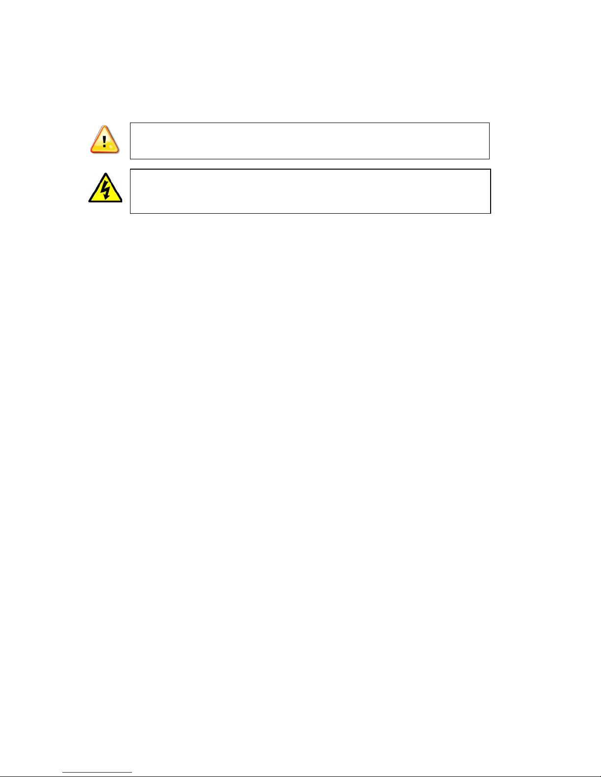
This symbol is intended to alert the user to the presence of important operating and
maintenance (servicing) instructions.
This symbol is intended to alert the user to the presence of uninsulated “dangerous
voltage” within the product’s enclosure that may be of sufficient magnitude to constitute a
risk of electrical shock.
Page 4

v2.0 3/21/11
4
4. WIRING CONNECTIONS
a. Connect the power supply’s DC plug to the camera’s power outlet.
b. Connect the camera to the monitor with a 75Ω coaxial video cable.
c. Connect unshielded twisted pair (UTP) control cable between the camera’s RS485
port and the PTZ controller. Be sure wire polarities are the same at each connection.
The camera’s violet wire (A) is + positive and the white wire (B) is – negative.
d. Connect power supply’s AC plug to a suitable AC power outlet.
e. Adjust the lens direction according to the required surveillance area and environment.
5. FUNCTIONS and OPERATION
Configuring the ST-PTZMINI-540W
The ST-PTZMINI-540W’s control board has an 10-DIP switch used to set a number of
parameters including address, communications protocols and control protocols. Any
command used should conform to the target camera and that camera’s response should occur
only when it has been addressed.
Of the 10 DIP switches:
Switches 1, 2, 3, 4, 5, 6, 7 and 8 are for setting the camera address.
Switches 9 and 10 are for setting the communications baud rate.
Set Camera Address
The tables below indicate DIP switch settings for creating the camera’s address. “1”
indicates the switch is set “ON” while “0” indicates the switch is set “OFF”.
Page 5

v2.0 3/21/11
5
Address
Address Switch
Address
Address Switch
Code
1 2 3 4 5 6 7 8
Code
1 2 3 4 5 6 7 8
1
1 0 0 0 0 0 0 0
33
1 0 0 0 0 1 0 0
2
0 1 0 0 0 0 0 0
34
0 1 0 0 0 1 0 0
3
1 1 0 0 0 0 0 0
35
1 1 0 0 0 1 0 0
4
0 0 1 0 0 0 0 0
36
0 0 1 0 0 1 0 0
5
1 0 1 0 0 0 0 0
37
1 0 1 0 0 1 0 0
6
0 1 1 0 0 0 0 0
38
0 1 1 0 0 1 0 0
7
1 1 1 0 0 0 0 0
39
1 1 1 0 0 1 0 0
8
0 0 0 1 0 0 0 0
40
0 0 0 1 0 1 0 0
9
1 0 0 1 0 0 0 0
41
1 0 0 1 0 1 0 0
10
0 1 0 1 0 0 0 0
42
0 1 0 1 0 1 0 0
11
1 1 0 1 0 0 0 0
43
1 1 0 1 0 1 0 0
12
0 0 1 1 0 0 0 0
44
0 0 1 1 0 1 0 0
13
1 0 1 1 0 0 0 0
45
1 0 1 1 0 1 0 0
14
0 1 1 1 0 0 0 0
46
0 1 1 1 0 1 0 0
15
1 1 1 1 0 0 0 0
47
1 1 1 1 0 1 0 0
16
0 0 0 0 1 0 0 0
48
0 0 0 0 1 1 0 0
17
1 0 0 0 1 0 0 0
49
1 0 0 0 1 1 0 0
18
0 1 0 0 1 0 0 0
50
0 1 0 0 1 1 0 0
19
1 1 0 0 1 0 0 0
51
1 1 0 0 1 1 0 0
20
0 0 1 0 1 0 0 0
52
0 0 1 0 1 1 0 0
21
1 0 1 0 1 0 0 0
53
1 0 1 0 1 1 0 0
22
0 1 1 0 1 0 0 0
54
0 1 1 0 1 1 0 0
23
1 1 1 0 1 0 0 0
55
1 1 1 0 1 1 0 0
24
0 0 0 1 1 0 0 0
56
0 0 0 1 1 1 0 0
25
1 0 0 1 1 0 0 0
57
1 0 0 1 1 1 0 0
26
0 1 0 1 1 0 0 0
58
0 1 0 1 1 1 0 0
27
1 1 0 1 1 0 0 0
59
1 1 0 1 1 1 0 0
28
0 0 1 1 1 0 0 0
60
0 0 1 1 1 1 0 0
29
1 0 1 1 1 0 0 0
61
1 0 1 1 1 1 0 0
30
0 1 1 1 1 0 0 0
62
0 1 1 1 1 1 0 0
31
1 1 1 1 1 0 0 0
32
0 0 0 0 0 1 0 0
255
1 1 1 1 1 1 1 1
Set Communications Baud Rate
“1”indicates the switch is set “ON” while “0” indicates the switch is set “OFF”.
Baud Rate
Switch #
9 10
1200bps
1 1
2400bps
0 1
4800bps
1 0
9600bps
0 0
Page 6

v2.0 3/21/11
6
FUNCTIONS
The user can control camera and lens movement through the use of a PTZ Controller. Further,
the user can track the target or shift the view while the camera’s focal length can be adjusted
to the required view angle and target image sizing. Note although manual adjustment of focal
length is possible while the dome moves at a high speed, the ST-PTZMINI-540W allows for
automatic horizontal and vertical dome speed adjustment consistent with lens focal length and
zoom settings so no information is lost during camera movement.
Zoom Control
The user can adjust the image farther or nearer to acquire a panoramic view by use a PTZ
Controller’s Zoom - / Zoom + controls. The ST-PTZMINI-540W supports both digital and
optical variable focus. There are certain conditions whereby the camera may not be able to
auto focus:
The target is not in the center of the image.
The target is in bright light (e.g., neon light, spot light).
The target or object is moving too fast.
The target is a large, square monotonous object such as a wall.
The target is too dark or vague.
The target is too small.
Surveillance Functions
A preset position is the storing of a camera location parameter such as horizontal angle,
inclination, or lens focus in memory and transferring them to the camera when needed.
Recalling and transferring preset positions is done through the PTZ Controller. The
ST-PTZMINI-540W supports 128 preset positions.
Set Preset Positions
The ST-PTZMINI-540W supports up to 128 preset positions. Setting the preset positions using
a PTZ Controller is done as follows by way of example:
Move the joystick so the camera is on the location or image for the first preset point.
Push Preset button on the PTZ Controller and press number 1 and ENTER for Preset
Position #1.
Move the joystick so the camera is on the location or image for the second preset
point. Push Preset button on the PTZ Controller and press number 2 and ENTER for
Preset Position #2.
Continue the above steps for each preset position to be entered.
To move the camera to an existing preset point press CALL and the appropriate
number. E.g., to point the camera to Preset Position #2 press CALL and 2.
Set Scanning
Auto Scanning – The camera performs a level scan back and forth among the left and right
limits at a set speed – is incorporated in the ST-PTZMINI-540W. Left and right limits and scan
speed are set using the PTZ Controller. Auto scan can be done using CALL #125 or pressing
the auto-scan button on the PTZ Controller. The camera will auto scan 360° back and forth.
The auto scan speed is fixed.
Linear Scanning – The camera may also be set to scan back and forth between two fixed
positions established as preset positions. The scanning speed can be set from 1° to 50° per
second. By way of example, and using 50° per second as the scan speed, via the PTZ
Page 7

v2.0 3/21/11
7
Controller:
Preset #126 for linear scanning.
Preset #1 to 50 (1 being slow, 50 being fast) as the speed index for total scan speed
time. Note each value refers to °/second (e.g., 1 = speed of 1°/second)
Move the controller’s joystick to the beginning location and adjust the image to be
viewed.
Preset #127 as the preset point for the beginning location.
Move the joystick to the ending location and adjust the image to be viewed.
Preset #128 as the preset point for the ending location.
Call 128 to activate the linear scan.
Tour
Automatic Tour is incorporated in the ST-PTZMINI-540W allowing preset points to be inserted
into a tour list. These preset points with timing pauses can be programmed as a tour route. In
so doing, the ST-PTZMINI-540W can automatically follow a predefined path or route. Up to 8
preset points and timing pauses can be stored in the camera. Two tour routes (#101 and
#102) can be created using 8 preset points each. The camera pauses 6 seconds at each
point. By way of example for Tour Route #101 using 3 preset points:
Preset 101.
For preset point 1 – move joy stick to the first location and Preset point 1.
For preset point 2 – move joy stick to the second location and Preset point 2.
For preset point 3 – move joy stick to the third location and Preset point 3.
Call 101 to activate Tour Route #101.
6. TROUBLESHOOTING
a. No picture after applying power – (i) check all plugs and cables are securely
connected to the proper connectors; (ii) ensure your power supply is providing the
correct voltage and current.
b. The picture has ripples – (i) check to see if the power supply is experiencing AC ripple,
if so a filter may be required; (ii) determine if the monitor is faulty; (iii) determine if
other peripheral equipment is causing ripple and if so make the necessary
adjustments.
c. The picture background continuously changes color – a fluorescent lamp’s magnetic
field may cause color roll, therefore, reduce the number of fluorescent lamps or
increase the distance between the camera and the lamps.
d. The picture appears smeared – (i) the power supply voltage level may be unstable,
therefore, try another power supply; (ii) ensure the cables are correctly connected
and/or the cables are of the correct impedance.
e. Other interference may require a SecurityTronix ground loop isolation filter.
f. Power is on, but the controller does not work – (i) check to make sure the DIP
switches for address and communications baud rate are properly set, (ii) check to
ensure the RS485 connections at the camera and the PTZ Controller have the same
polarity, (iii) check the integrity and continuity of the unshielded twisted pair (UTP)
control cable.
g. Additional troubleshooting assistance can be found on-line at www.securitytronix.com
in addition to support from SecurityTronix sales engineers at 1-610-429-1511.
Page 8

v2.0 3/21/11
8
APPENDIX: PELCO-D PROTOCOL
The ST-PTZMINI-540W uses the PELCO-D protocol. Below is a description of the protocol for
those installers or system integrators in need of the protocol’s details.
Data Form: 1 beginning position, 8 pieces for data, 1 ending position, invalid checking point.
Baud Rate: 2400, 4800, 9600, 19200bps.
Command Form:
Byte 1
Byte 2
Byte 3
Byte 4
Byte 5
Byte 6
Byte 7
Synchronized
Byte
Address
Code
Command
Code 1
Command
Code 2
Data Code 1
Data Code 2
Confirmation
Code
All data in the protocol as HEX
Synchronization Byte is 0FFH
Address Code is the logical address number of cameras.
Address Range is 01H – 0FFH
Form of Command Code:
Bit 7
Bit 6
Bit 5
Bit 4
Bit 3
Bit 2
Bit 1
Bit 0
Command
Code 1
0 0 0
Auto
Scan
0
Iris
Close
Iris
Open
Focus
Near
Command
Code 2
Focus
Far
Zoom
Wide
Zoom
Tele
Down
Up
Left
Right
0
Command Code 1: Bit 7, Bit 6, Bit 5, Bit 3 is 0 without exception. Bit 4 is auto scanning
control points (1/0 ON/OFF). Bit 2 Iris Smaller (1 valid). Bit 1 Iris Larger (1 valid). Bit 0
Focus Nearer (1 valid).
Command Code 2: Bit 7 Focus Farther (1 valid). Bit 6 & Bit 5 for zoom control: Bit 6 far
away from the object (1 valid), Bit 5 near the object (1 valid). Bit 4, Bit 3, Bit 2, Bit 1
separately control the movement down, up, left, right (1 valid). Bit 0 is 0 without exception.
Data Code 1: Controls the horizontal direction of speed 00 – 3FH.
Data Code 2: Controls the vertical direction of speed 00 – 3FH.
Confirmation Code Index: [Byte 2 + Byte 3 + Byte 4 + Byte 5 + Byte 6 / 100H].
Confirmation Code = MOD [Byte 2 + Byte 3 + Byte 4 + Byte 5 + Byte 6 / 100H].
Setting and Transferring Preset Command
Set the Command for Preset Positions
Byte 1
Byte 2
Byte 3
Byte 4
Byte 5
Byte 6
Byte 7
Synchronized
Byte
Address
Code
00H
03H
00H
Present
Point #
Confirmation
Code
Transfer the Command of Preset Positions
Byte 1
Byte 2
Byte 3
Byte 4
Byte 5
Byte 6
Byte 7
Synchronized
Byte
Address
Code
00H
07H
00H
Present
Point #
Confirmation
Code
Preset Point # Range is 00 – FFH
Page 9

v2.0 3/21/11
9
Turn On and Off the Command of Auxiliary Switches
Turn On the Command of Auxiliary Switches
Byte 1
Byte 2
Byte 3
Byte 4
Byte 5
Byte 6
Byte 7
Synchronized
Byte
Address
Code
00H
09H
00H
Auxiliary
Switch #
Confirmation
Code
Turn Off the Command of Auxiliary Switches
Byte 1
Byte 2
Byte 3
Byte 4
Byte 5
Byte 6
Byte 7
Synchronized
Byte
Address
Code
00H
0BH
00H
Auxiliary
Switch #
Confirmation
Code
Auxiliary Switch # Range is 01 – 08.
 Loading...