

Page 1
v2.2 8/11/11
1
INSTALLATION MANUAL
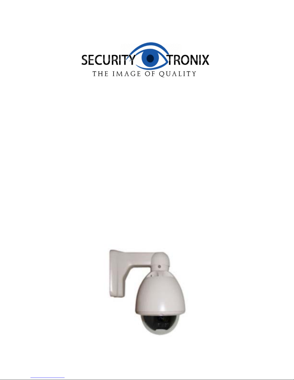
ST-PTZMINI-10XTA
Vandalproof Intelligent Dome PTZ
Color Camera With 10x Optical Zoom
Page 2

v2.2 8/11/11
2
PACKAGE CONTENTS
This package contains:
One ST-PTZMINI-10XTA vandal proof intelligent dome color camera
One installation manual
Note: The ST-PTZMINI-10XTA requires a minimum 12VDC 700mA power supply such as the
ST-PS12VDC1A or ST-PS12VDC2A.
PRODUCT DESCRIPTION
The ST-PZMINI-10XTA is a professional grade, IP-66 rated outdoor dome color camera with pan,
tilt and zoom (PTZ) capability. The camera’s full digital design allows the saving of all settings in
non-volatile memory. The camera features include a 10X optical zoom, a 3.8mm – 38mm lens, a
Sony Super HAD Color CCD and 480TVL resolution in color.
SPECIFICATIONS
ST-PTZMINI-10XTA
Specifications (Typical)
1. Image Sensor
1/4” SONY Super HAD Color CCD
2. Resolution
480TVL in color
3. Lens
3.8mm – 38mm auto-focus 10x motorized zoom lens
4. Effective Picture Elements
976x582 (NTSC)
5. Minimum Illumination
0.001 Lux/F2.0
6. Scanning System
535 lines, 60 field/sec (NTSC)
7. Video Output
Composite signal, 1.0VP-P, 75Ω
8. Signal to Noise Ratio
≥65dB (AGC off)
9. Synchronous System
Internal
10. Auto Electronic Shutter
1/60s ~ 1/100,000s
11. Gama Correction
0.45
12. Gain Control
Auto
13. White Balance
Auto
14. Pan Range
0° ~ 360°
15. Tilt Range
0° ~ 90°
16. Pan Speed
Max 40°/sec Preset: 32
17. Power
DC12V 700mA
18. Operating Relative Humidity
95% maximum
19. Operating Temperature
14°F – 122°F
20. Dimensions
5.4”x8.3”
21. Weight
5.5 lbs
Page 3
v2.2 8/11/11
3
INSTALLATION AND OPERATION
CAUTION: To reduce the risk of electrical shock do not remove the cover or back of this
unit other than to set camera address and baud rate. No user serviceable parts are inside.
CAUTION: To prevent electric shocks and risk of fire hazards, do not use other than
specified power source.
1. UNPACKING and HANDLING
Each unit is shipped assembled and factory tested.
Ensure that all accessories are removed from the container before discarding packing material
2. MECHANICAL INSPECTION
Inspect the front and rear of the equipment for shipping damage. Make sure the equipment is
clean, and no connectors are broken, damaged, or loose. If equipment appears to be
damaged or defective please contact your distributor or Securitytronix at 1-610-429-1511 for
assistance.
3. SPECIAL ATTENTION
a. The installer must comply with electrical safety standards. There must be sufficient
space between the camera’s power supply and video line and any high voltage
equipment and/or cables.
b. To help ensure the camera’s life and proper operation do not point the camera
towards the sun or strong light.
c. Do not install the camera in an environment where the temperature is above 122° F.
d. Do not install the camera near a magnetic field or a high-power motor.
e. Do not mount the camera near a radiator or heater.
f. Only use a dry cloth to clean the camera. If there is dirt that is difficult to remove wipe
gently with a mild detergent. Never use strong or abrasive detergents.
g. A minimum 12VDC 700mA power supply must be used. AC power cannot be applied.
Using an AC or other incorrect power supply will damage the camera.
h. Only qualified installers are allowed to install, test and disassemble the camera.
i. The camera is a low voltage product. If installed outdoors proper safety and lightening
grounding are required.
This symbol is intended to alert the user to the presence of important operating and
maintenance (servicing) instructions.
This symbol is intended to alert the user to the presence of uninsulated “dangerous
voltage” within the product’s enclosure that may be of sufficient magnitude to constitute a
risk of electrical shock.
Page 4

v2.2 8/11/11
4
4. WIRING CONNECTIONS
a. Connect the power supply’s DC plug to the camera’s power outlet.
b. Connect the camera to the monitor with a 75Ω coaxial video cable.
c. Connect unshielded twisted pair (UTP) control cable between the camera’s RS485
port and the PTZ controller. Be sure wire polarities are the same at each connection.
The camera’s violet wire (A) is + positive and the grey wire (B) is – negative.
d. Connect power supply’s AC plug to a suitable AC power outlet.
e. Adjust the lens direction according to the required surveillance area and environment.
Page 5

v2.2 8/11/11
5
5. SETTING CAMERA ADDRESS, PROTOCOL and BAUD RATE USING DIP-SWITCHES
Page 6

v2.2 8/11/11
6
Setting Camera Baud Rate: DIP-Switches 7, 8
Baud Rate
Switch 7 8
1200bps
1 0
2400bps
0 0
4800bps
1 1
9600bps
0 1
Setting Camera Protocol: DIP-Switch 9
Protocol
Switch 9
PELCO-P
1
PELCO-D
0
Setting RS485 Terminal Resistance: DIP-Switch 0
RS485 Resistance
Switch 0
Connect to 120Ω Resistor
1
No Connection to 120Ω Resistor
0
6. FUNCTIONS
The camera uses preset commands to achieve a number of functions. Use CLEAR / SET /
GOTO and the preset number to perform these functions. Consult your PTZ controller’s
manual as how to set, clear and recall presets.
Set Preset Point Numbers:
Preset No.
Function
1 – 32
Set Preset Point
76
Set Home Point
77
Set Home Point Wait Time to 64
78
Set Home Point Wait Time to 128
79
Set Home Point Wait Time 192
80
Set Home Point Wait time to 255
81
Enable auto return to Home Point
82
Disable auto return to Home Point
92
Set Left Limited Point
93
Set Right Limited Point
94
Reset Original Point
240
Clean Setup
241
Initialize System
242
Start TOUR Setup
243
End TOUR Setup
247
Start TOUR
248
Stop TOUR
Page 7

v2.2 8/11/11
7
Clear Preset Point Numbers:
Preset No.
Function
1 – 32
Clear Preset Point
76
Clear Home Point
92
Clear Left Limited Point
93
Clear Right Limited Point
GoTo Preset Point Number:
Preset No.
Function
1 – 32
GoTo Preset Point
34
GoTo Pan Zero Point
76
GoTo Home Point
92
GoTo Left Limited Point
93
GoTo Right Limited Point
99
Start Auto Scan
To Set and Run a Tour:
a. Input SET preset 242 to begin tour learning.
b. Send GOTO preset command so the camera will recognize this point as a tour point.
For example, if the camera is to tour at point 1, 3, and 6 input GOTO preset point 1,
GOTO preset point 3 and GOTO preset point 6.
c. Input SET preset 243 to end tour learning.
d. Input SET preset 247 to start tour.
e. Input SET preset 248 to stop tour.
7. TROUBLESHOOTING
a. No picture after applying power – (i) check all plugs and cables are securely
connected to the proper connectors; (ii) ensure your power supply is providing the
correct voltage and current.
b. The picture has ripples – (i) check to see if the power supply is experiencing AC ripple,
if so a filter may be required; (ii) determine if the monitor is faulty; (iii) determine if
other peripheral equipment is causing ripple and if so make the necessary
adjustments.
c. The picture background continuously changes color – a fluorescent lamp’s magnetic
field may cause color roll, therefore, reduce the number of fluorescent lamps or
increase the distance between the camera and the lamps.
d. The picture appears smeared – (i) the power supply voltage level may be unstable,
therefore, try another power supply; (ii) ensure the cables are correctly connected
and/or the cables are of the correct impedance.
e. Other interference may require a Securitytronix ground loop isolation filter.
f. Power is on, but the controller does not work – (i) check to make sure the DIP
switches for address and communications baud rate are properly set, (ii) check to
ensure the RS485 connections at the camera and the PTZ Controller have the same
polarity, (iii) check the integrity and continuity of the unshielded twisted pair (UTP)
control cable.
g. Additional troubleshooting assistance can be found on-line at www.securitytronix.com
in addition to support from Securitytronix sales engineers at 1-610-429-1511.
 Loading...