

Page 1
V1.0 12/15/11
INSTALLATION MANUAL
ST-PTZIR530-36
IP66 Rated High-Speed Intelligent Dome
PTZ IR Color Camera
Copyright North American Cable Equipment, Inc.
Page 2

v1.0 12/15/11
2
TABLE&OF&CONTENTS&
&
PACKAGE'CONTENTS ................................................................................................................... 3!
PRODUCT'DESCRIPTION............................................................................................................. 3!
SPECIFICATIONS............................................................................................................................ 3!
INSTALLATION'AND'OPERATION ............................................................................................ 4!
1.! UNPACKING'and'HANDLING........................................................................................................ 4!
2.! MECHANICAL'INSPECTION........................................................................................................... 4!
3.! SPECIAL'ATTENTION ..................................................................................................................... 4!
4.! CAMERA'SETUP................................................................................................................................ 5!
Protocol Set Up................................................................................................................................................... 5!
Camera Address Set Up................................................................................................................................ 6!
5.! PHYSICAL'INSTALLATION............................................................................................................ 6!
6.! FUNCTIONS'and'OPERATION ...................................................................................................... 9!
System Information........................................................................................................................................10!
Display.................................................................................................................................................................... 10 !
Dome Settings ................................................................................................................................................... 12!
Camera Setup.....................................................................................................................................................20!
Operation Setup................................................................................................................................................22!
Restart.....................................................................................................................................................................26!
Factory Defaults ............................................................................................................................................... 27!
Help...........................................................................................................................................................................27!
7.! TROUBLESHOOTING .................................................................................................................... 28!
APPENDIX'A ..................................................................................................................................29!
&
Page 3

v1.0 12/15/11
3
PACKAGE&CONTENTS&
This package contains:
One ST-PTZIR530-36 high-speed intelligent dome color camera.
One mounting bracket with mounting hardware.
One installation manual.
PRODUCT&DESCRIPTION&
The ST-PTZ530-36 is an IP66 rated professional grade intelligent dome color camera with
pan, tilt and zoom (PTZ) capability of 530TVL using a 3.4mm to 122.4mm F1.6-F4.5 zoom
lens. This camera is capable of 360° continuous panning without any blind areas, supports
255 addresses and 220 programmable presets and offers multiple cruising, auto-scan, and
pattern tour tracks. All settings are stored in non-volatile memory. The ST-PTZ530-36 is an
all weather camera with integrated heater and blower.
SPECIFICATIONS&
1. Image Sensor
¼” EX-View HAD CCD
2. Resolution
530TVL
3. Picture Elements
NTSC: 768x494
4. Lens
3.4mm ~ 122.4mm, F1.6-F4.5
5. Illumination
0.01 Lux IR On
6. Zoom
432X, 36X Optical, 12X Digital
7. Sync system
internal/External (V-Lock)
8. S/N Ratio
50dB
9. White Balance
ATW / Indoor / Outdoor / Manual / AWB / One Push WB
10. Gain
Auto / Manual
11. Video Output
1Vp-p Composite Video, 75Ω
12. Communications
RS485
13. Protocol
PELCO-P, PELCO-D
14. No. of Programmable Presets
220
15. Focus
Auto / Manual
16. Iris
Auto / Manual
17. No. of Cruising Tracks
8
18. No. of Auto Scan Tracks
8
19. No. of Privacy Zones
8
20. No. of Pattern Tours
4
21. Continuous Pan
360°
22. Manual Speed
0.01° ~ 120°/s
23. Max. Cruising Speed
120°/s
24. No. of Addresses
255
25. Operating Temperature
-13°F ~ 122°F (IR Off), -13°F ~ 86°F (IR On)
26. Operating Relative Humidity
<95%
27. Power
110 ~ 220VAC @0.5A
Page 4
v1.0 12/15/11
4
INSTALLATION&AND&OPERATION&
CAUTION: To reduce the risk of electrical shock do not remove the cover or back of
this unit. No user serviceable parts are inside.
CAUTION: To prevent electric shocks and risk of fire hazards, do not use other than
specified power source.
1. UNPACKING&and&HANDLING&
Each unit is shipped assembled and factory tested.
Ensure that all accessories are removed from the container before discarding packing
material
2. MECHANICAL&INSPECTION&
Inspect the front and rear of the equipment for shipping damage. Make sure the
equipment is clean, and no connectors are broken, damaged, or loose. If equipment
appears to be damaged or defective please contact your distributor or Securitytronix at
1-610-429-1511 for assistance.
3. SPECIAL&ATTENTION&
a. The installer must comply with electrical safety standards. There must be
sufficient space between the camera’s power supply and video line and any high
voltage equipment and/or cables.
b. To help ensure the camera’s life and proper operation do not point the camera
towards the sun or strong light.
c. Do not install the camera in an environment where the temperature is above 122°
F.
d. Do not install the camera near a magnetic field or a high-power motor.
e. Do not mount the camera near a radiator or heater.
f. The installation site and material must fully support the weight of the product.
g. Only use a dry cloth to clean the camera. If there is dirt that is difficult to remove
wipe gently with a mild detergent. Never use strong or abrasive detergents.
This symbol is intended to alert the user to the presence of important operating and
maintenance (servicing) instructions.
This symbol is intended to alert the user to the presence of uninsulated “dangerous
voltage” within the product’s enclosure that may be of sufficient magnitude to constitute a
risk of electrical shock.
Page 5
v1.0 12/15/11
5
h. This camera uses AC power of 100 ~ 240 volts at 0.5A. Using a DC or other
incorrect power supply or source will damage the camera.
i. Only qualified installers are allowed to install, test and disassemble the camera.
j. The camera is a low voltage product. If installed outdoors proper safety and
lightning grounding are required in addition to surge protection.
k. Before installing be sure the grounding, wiring, input power, voltage, DIP
switches, communication protocol and baud rate are correctly set prior to
powering up and using.
4. CAMERA&SETUP&
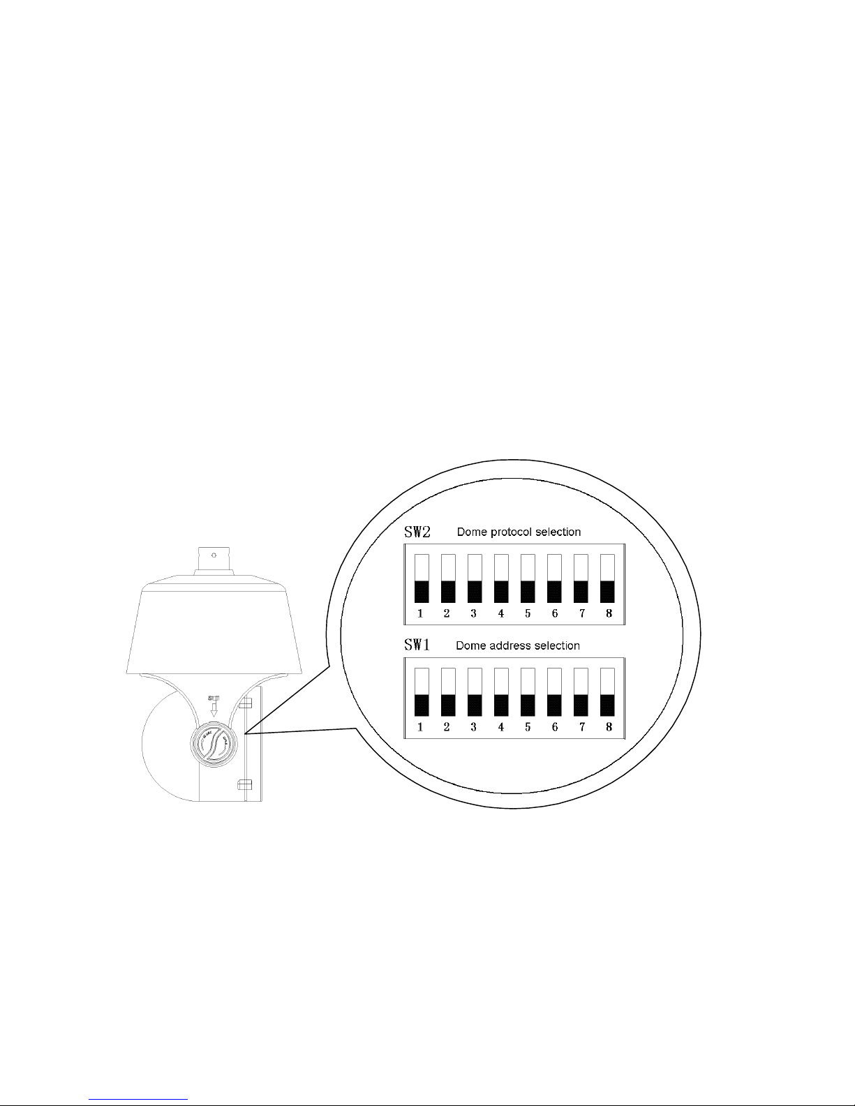
It is advisable to configure the camera’s settings prior to physically installing the unit.
To set the camera’s address and protocol remove the “settings cover” on the side of the
camera. This will expose two sets of 8-bit DIP switches, one each to set the camera’s
protocol and address.
Protocol Set Up
The camera supports PELCO-P and PELCO-D protocols and three baud rates: 9600,
4800 and 2400bps. Using SW2 and the table below:
DIP Switches 1, 2 and 3 set the protocol (“1” means “ON”, “0” means “OFF”)
DIP Switches 4 and 5 set the baud rate (“1” means “ON”, “0” means “OFF”)
Page 6
v1.0 12/15/11
6
Protocol
Switch 1
Switch 2
Switch 3
PELCO-D
0 1 0
PELCO-P
1 0 0
Reserved
… … …
Baud Rate
Switch 4
Switch 5
9600
0
0
4800
1
0
2400
0
1
Reserved
1
1
Camera Address Set Up
SW1 uses all of the 8-bit switches to set up to 255 camera addresses. The 1st bit is the
lowest and the 8
th
bit is the highest.
See Appendix A for SW1 DIP Switch configurations for PELCO-P and PELCO-D
protocols. Note the DIP Switch settings are slightly different for each protocol.
&
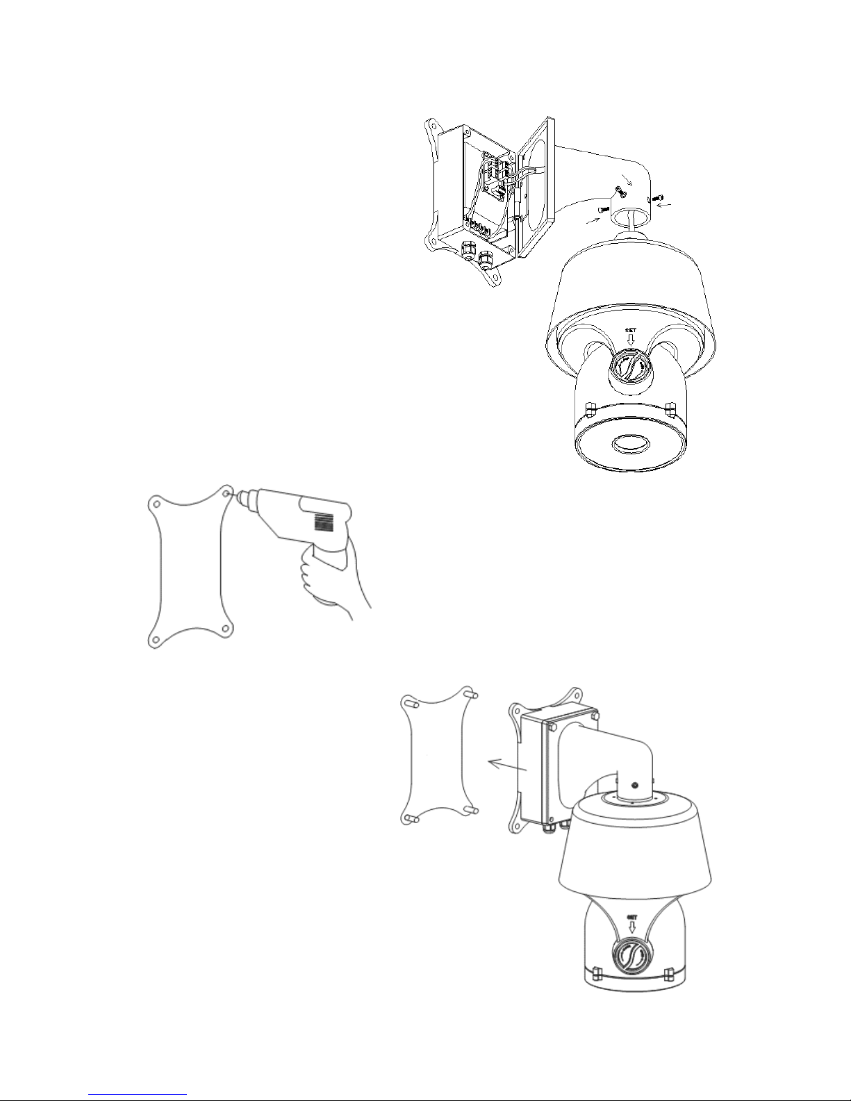
5. PHYSICAL&INSTALLATION&
Unscrew the power box from the mounting bracket. Then thread the cables across the
bracket and connect to the circuit board in the power box.
Page 7
v1.0 12/15/11
7
Install the camera dome to the bracket
using the four hexagon screws. It is
advisable to apply a waterproof sealant to
the joint gap where the camera dome joins
the bracket.
Attach the mounting template to the location where
the camera is to be mounted. Drill holes according to
the template and install the mounting bolts.
Install the entire unit (camera body,
bracket and power box) to the mounting
bolts and tighten.
Page 8
v1.0 12/15/11
8
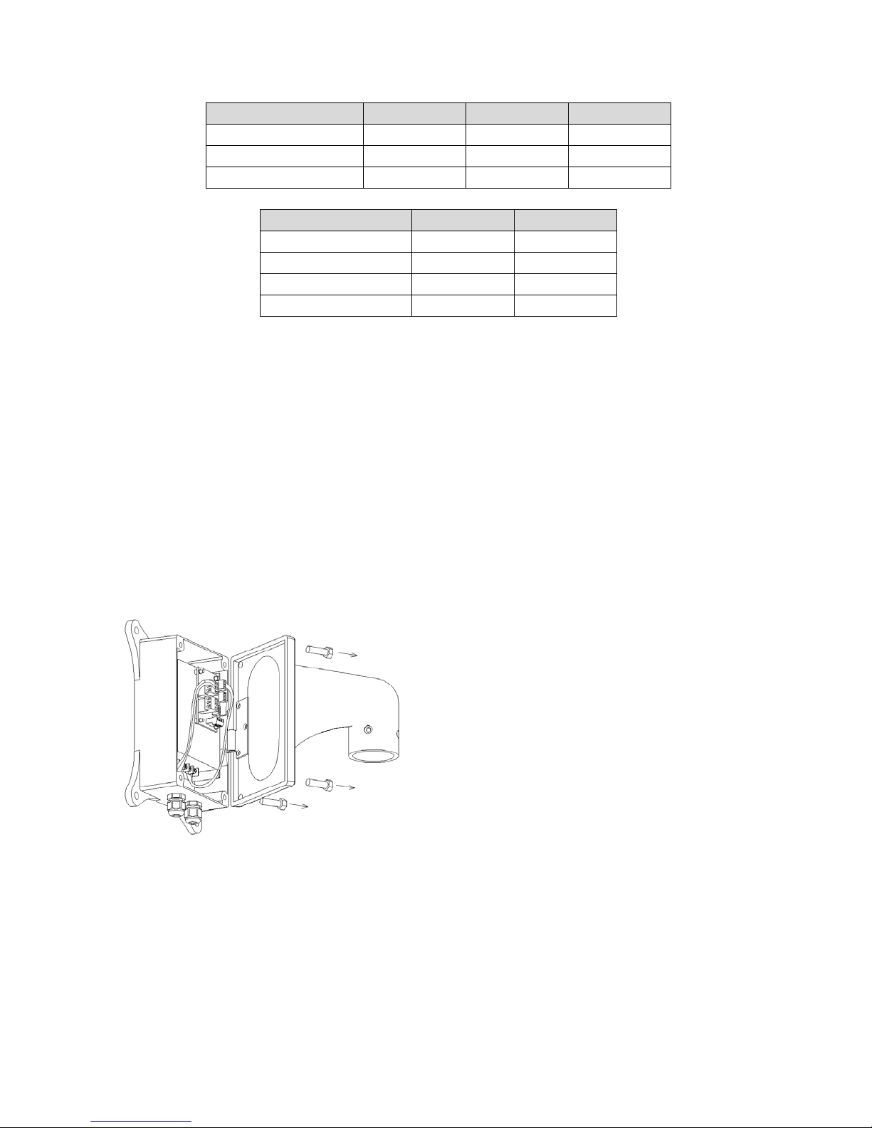
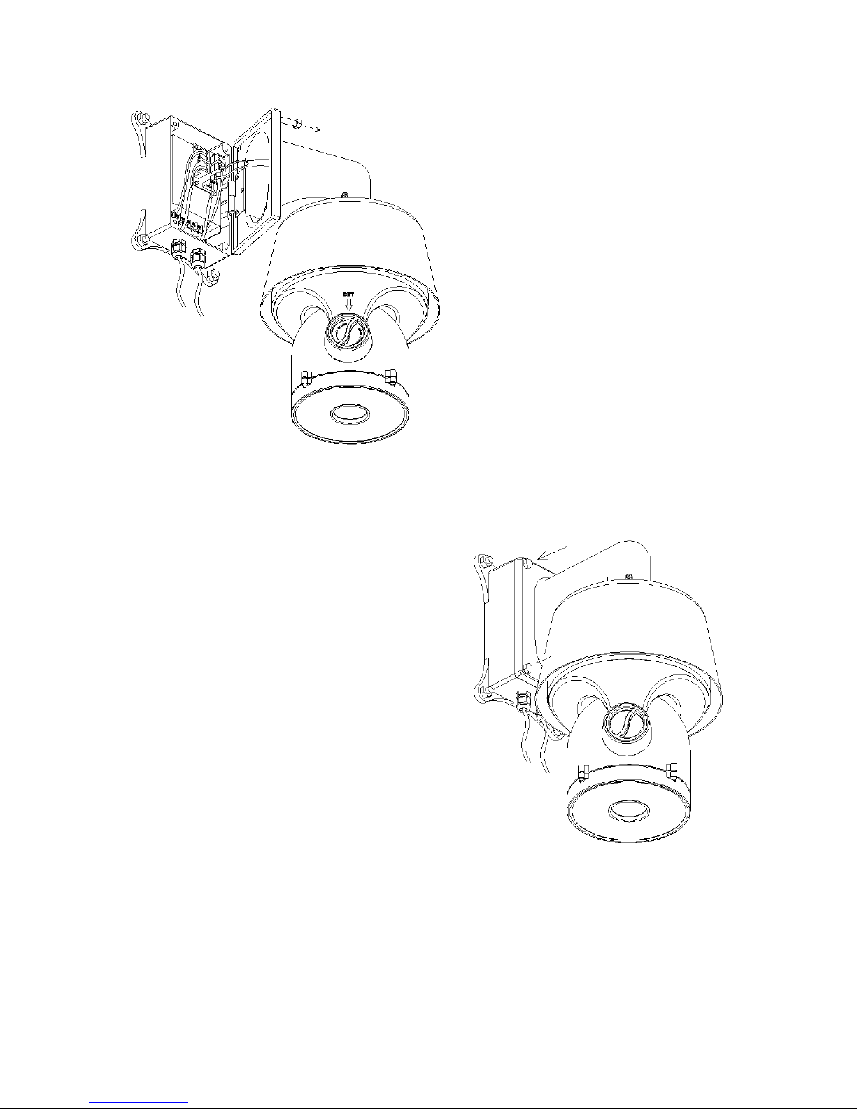
Remove two screws from the power box
and open it.
Thread the power cable through the
waterproof head on the left and the RS485
and video cable through the waterproof
head on the right.
Connect the cables to the circuit board
and double check to ensure each cable is
connected to its proper location. Damage
may occur if cables are improperly
connected.
After all cables are connected, tighten the
two heads. It is advisable to apply
waterproof sealant to the heads.
Close the power box and tighten the bracket to the
box. Double check all bolts and screws are tight. It
is advisable to apply waterproof sealant to all joint
gaps.
After the camera is physically mounted and
installed:
Connect the camera to the monitor with a 75Ω coaxial video cable.
Connect power supply’s AC plug to a suitable AC power outlet.
Make an RS485 connection between the camera and the PTZ controller. Ensure
the connections at the PTZ controller and camera have the same polarities.
Page 9
v1.0 12/15/11
9
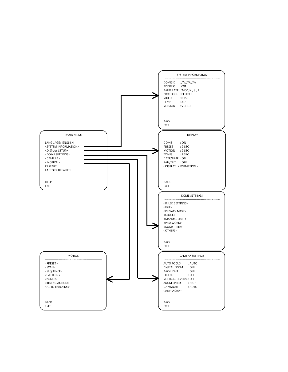
6. FUNCTIONS&and&OPERATION&
From the PTZ controller calling preset position 95 will display the camera’s On Screen
Display (OSD) menu. The camera’s OSD Menu Tree is below.
!
! ! ! !
!
!! ! ! !
! ! ! ! !
Page 10

v1.0 12/15/11
10
System Information
A = Camera Dome ID E = TV System (NTSC or PAL)
B = Camera Dome Address F = Camera’s Internal Temperature
C = Baud Rate G = Version
D = Protocol
Display
Call preset 95 to enter the OSD Menu and move the PTZ controller’s joystick to select
DISPLAY and press IRIS OPEN to enter submenu DISPLAY.
A = DOME. Press IRIS OPEN to set the Dome Setting with the ON/OFF option.
B = PRESET. Press IRIS OPEN to set the Preset Setting with ON / OFF / 2SEC / 5SEC /
10SEC option
C = MOTION. Press IRIS OPEN to set the Auto Setting with ON / OFF/ 2SEC / 5SEC /
10SEC option.
D = ZONES. Press IRIS OPEN to set the Zones Settings with ON / OFF / 2SEC / 5SEC /
10SEC option.
E = DATE/TIME. Press IRIS OPEN to set the Date/Time Settings and move the joystick
to select ON / OFF / 2SEC / 5SEC / 10SEC option.
A
B
C
D
E
F
G
A
B
C
D
E
F
G
Page 11

v1.0 12/15/11
11
F = PAN/TILT. Press IRIS OPEN to set the Pan/Tilt Settings and move the joystick to
select ON / OFF / 2 SEC / 5SEC / 10 SC option.
G = DISPLAY POSITION. This submenu allows the user to set where information is
displayed on the monitor. Move the cursor to Display Position and press IRIS OPEN to
enter the submenu.
A = DATE/TIME. Press IRIS OPEN to set the Date/Time Setting and move
the joystick to move the Date/Time to the desired position. Press IRIS OPEN
to confirm.
B = DOME TITLE. Press IRIS OPEN to set the Dome Setting and move the
joystick to move the Dome to the desired position. Press IRIS OPEN to
confirm.
C = ZONES. Press IRIS OPEN to set the Zones Setting and move the
joystick to move the Zone to the desired position. Press IRIS OPEN to
confirm.
D = MOTION. Press IRIS OPEN to set the Auto Setting and move the joystick
to move the Auto to the desired position. Press IRIS OPEN to confirm.
E = PAN/TILT. Press IRIS OPEN to set the Pan/Tilt Setting and move the
joystick to move the Pan/Tilt to the desired position. Press IRIS OPEN to
confirm.
A
B
C
D
E
Page 12

v1.0 12/15/11
12
Dome Settings
Call preset position 95 to display the OSD Menu and move the PTZ controller’s joystick
to the DOME submenu. Press IRIS OPEN to enter the DOME submenu.
A = IR LED SETTINGS. Move the cursor to IR LED and press the IRIS OPEN to access
the IR LED submenu.
!!!!!! !
A1 = CONTROL MODE. Move the cursor to CONTROL MODE and press IRIS
OPEN to select the IR light control type. Move the joystick to set the IR light control
type as “External Auto / Internal Auto / Timing / On / Off ”.
External Auto – Turning on or off the IR LED will depend on the light sensor.
When the light sensor detects the environmental light level is lower than the
IR LEDs’ threshold the IR LEDs will turn on and the camera will switch from
color to black and white. When the environmental light level is higher than the
IR LEDs’ threshold the IR LEDs will turn off and the camera switches from
black and white to color.
Internal Auto – Activation of the LEDs are determined by the light level
reaching the CCD, not the external light sensor.
TIMING – The IR LEDs will turn on or off according to the time set by user.
ON – The IR LEDs are always on.
A
B
C
D
E
F
G
H
A1
B1
C1
D1
E1
F1
G1
H1
I1
Page 13

v1.0 12/15/11
13
OFF – The IR LEDs are always off.
NOTE: The camera’s D/N AUTO is valid unless the camera is set to “Internal
Synchronization Auto”
B1 = THRESHOLD. Move the cursor to THRESHOLD and press IRIS OPEN to
select the desired value. The user can adjust the environmental light threshold value
to suit specific locations. For External Synchronization Auto the default value is
1~2Lux. The threshold value can be set from 1 to 10 with 1 being weak or dim light
and 10 being strong or bright light.
C1 = SENSITIVTY SETUP. When the IR LEDs are on the environmental light
threshold needed to turn off the IR LEDs has a delay. 1 represents high sensitivity
and the delay range is narrow allowing the IR LEDs to turn on and off frequently in
certain light conditions. 10 represents low sensitivity and the delay range is wide
thereby causing the IR LEDs to turn on and off less frequently. The default value is 5.
D1 = START TIME. Press IRIS OPEN to enter the START TIME submenu and move
the joystick left or right to select the desired time value to be changed, then move the
joystick up or down to change the value.
E1 = STOP TIME. Press IRIS OPEN to enter the STOP TIME submenu and move
the joystick left or right to select the desired time value to be changed, then move the
joystick up or down to change the value.
NOTE: It is more effective to set the IR LED start and stop times in the Timing Mode.
F1 = ZOOM MATCH. Press IRIS OPEN to set the ZOOM MATCH. When OPEN is
selected the illumination and power of the IR LEDs are matched with the camera’s
illumination distance. With a different zoom the IR LEDs will automatically adjust its
power. When CLOSE is selected the IR LED illumination level is set manually by the
user. It is recommended that Open Zoom Match be selected.
G1 = LED 1 POWER. Light group 1 consists of the perimeter IR LEDs and
illumination for longer distances. Press IRIS OPEN to set the illumination value.
H1 = LED 2 POWER. Light group 2 consists of the center circular IR LEDs and
illumination of medium distances. Press IRIS OPEN to set the illumination value.
I1 = LED 3 POWER. Light group 3 consists of the inner IR LEDs and illumination of
shorter distances. Press IRIS OPEN to set the illumination value.
NOTE: If zoom match is set to off, the manual adjustment of the illumination levels
will be required.
NOTE: If zoom match is set to on, the adjustment illumination levels of the Light
Groups is done automatically.
Page 14

v1.0 12/15/11
14
B = STANDBY SETTINGS. Move the cursor to STANDBY SETTINGS and press IRIS
OPEN to enter the STANDBY SETTINGS submenu.
A1 = STANDBY TIME. Move the cursor to TIME and press IRIS OPEN to set up the
time. Move the joystick and time can be set to 30sec / 2min / 5min / 10min. Press
IRIS OPEN to confirm.
B1 = STANDBY ACTION. Move the cursor to MOTION and press IRIS OPEN to set
up the motion. Move the joystick and motion can be set to preset 1 /scan 1 /cruising
tour 1 / pattern tour 1 / no control. Press IRIS OPEN to confirm.
C = PRIVACY MASK. Move the cursor to PRIVACY MASK and press IRIS OPEN to
enter the PRIVACY MASK SETTINGS submenu.
A1 = PRIVACY MASK. Move the cursor to MASK NO. and press IRIS OPEN to set
up. Move the joystick to select any one of eight privacy masks.
B1 = ENABLE. Move the cursor to ENABLE and press IRIS OPEN to enable the
privacy mask. Move the joystick to select the mask’s state: On / Off.
C1 = SETUP. Move the cursor to SET and press IRIS OPEN to set up the privacy
mask’s position. Press IRIS OPEN to confirm. Then move the cursor to the privacy
A1
B1
A1
B1
C1
D1
Page 15

v1.0 12/15/11
15
mask, press IRIS OPEN to enter the privacy size setting and move the joystick to
adjust the size of the privacy area. Press IRIS OPEN to confirm.
D1 = DELETE. Move the cursor to DELETE and press IRIS OPEN to delete the
selected privacy mask.
D = CLOCK. Move the cursor to CLOCK and press IRIS OPEN to enter the CLOCK
submenu.
A1 = DATE SETTING. Move the cursor to DATE and press IRIS OPEN to set up the
date. Shift the joystick right or left to the desired setting position, then move the
joystick up or down to adjust the date. Press IRIS OPEN to confirm.
B1 = TIME SETTING. Move the cursor to TIME and press IRIS OPEN to set up the
time. Shif the joystick right or left to the desired setting position, then move the
joystick up or down to adjust the time. Press IRIS OPEN to confirm.
E = MANUAL LIMIT. Move the cursor to MANUAL LIMIT and press IRIS OPEN to enter
the MANUAL LIMIT submenu.
A1
B1
A1
B1
C1
Page 16

v1.0 12/15/11
16
A1 = SETUP LEFT LIMIT. Move the cursor to LEFT LIMIT and press IRIS OPEN to
set up.
B1 = SETUP RIGHT LIMIT. Move the cursor to RIGHT LIMIT and press IRIS OPEN
to set up.
C1 = MANUAL CONTROL. Move the cursor to MANUAL LIMIT and press IRIS
OPEN to set up. Move the joystick to select On / Off.
F = PASSWORD SETTINGS. Move the cursor to PASSWORD and press IRIS OPEN to
enter the PASSWORD SETTINGS submenu.
A1 = MODIFY PASSWORD. Move the cursor to EDIT PASSWORD and press IRIS
OPEN to enter the password modification mode. Input the old password first. Input
the new password. Press IRIS OPEN to confirm. The default password is “111111”.
B1 = PASSWORD PROTECTION. Move the cursor to ENABLE and press IRIS
OPEN to enter the password protection mode. Move the joystick up or down to
enable or disable password protection. Press IRIS OPEN to confirm. When password
protection is enabled, enter the password before opening the menu.
Page 17

v1.0 12/15/11
17
G = DOME TITLE SETUP. Move the cursor to DOME TITLE SETUP and press IRIS
OPEN to enter the DOME TITLE SETUP submenu.
! ! !!!!!!!!!!!! !
! ! !!!!!!!!!!!! !
! ! !!!!!!!!!!!! !
Page 18

v1.0 12/15/11
18
INPUT METHOD.
Move the cursor to INPUT and press IRIS OPEN to enter the information edit
mode. Move the joystick left and right to move the cursor “← ” and press IRIS
OPEN to delete the character and press IRIS CLOSE to exit the edit mode.
Move the cursor to the line below “INPUT”. Press IRIS OPEN to enter the
INPUT METHOD setup. Move the joystick up and down to chose the desired
input method: English Capital / English Lower Case / Chinese / Number /
Special Character.
Move the cursor to one line below “INPUT” and press IRIS OPEN to enter the
character input mode. The selected character twinkles. Move the joystick to
the desired character and press IRIS OPEN to input the desired character
next to “←” in the input information block.
Page 19

v1.0 12/15/11
19
H = OTHER OPTIONS. Move the cursor to OTHER OPTIONS and press IRIS OPEN to
enter the OTHER OPTIONS submenu.
A1 = TEMPERATURE CONTROL MODE. Move the cursor to the TEMPERATURE
MODE and press IRIS OPEN to enter the set up. Use the joystick to select “Cool /
Auto / Heat / Off” option and press IRIS OPEN to confirm the selection.
NOTE: With the IR LEDs on the fans will be set as “always on”.
B1 = PRESET FREEZE. In calling the preset setup menu, move the cursor to
PRESET FREEZE and press IRIS OPEN to enter set up. Move the joystick to select
“On / Off’ and press IRIS OPEN to confirm.
C1 = AUTO FLIP. When the camera dome rotates 90° in the vertical direction and
the user wants to continue the vertical rotation the dome will automatically rotate by
180° in 2 seconds. Press IRIS OPEN to turn this function On or Off.
D1 = AUTO STOP TIME. Auto pause time refers to the period of time when the
dome does not receive any input, and after that the camera will automatically pause.
Options are 15, 30 and 60 seconds.
E1 = MENU OFF TIME. The menu will automatically shut off after a period of
inactivity. Move the cursor to MENU OFF TIME and press IRIS OPEN to set up.
Move the joystick up or down to select the “1 mins / 2 mins/ 5 mins / 10 mins” option.
F1 = NORTH SET. Move the cursor to NORTH SET and press IRIS OPEN to enter
the set up mode. When “Press IRIS OPEN to Confirm” is displayed the user can
move the dome to a horizontal zero position (North). Press IRIS OPEN to set this
position as the zero position.
A1
B1
C1
D1
E1
Page 20

v1.0 12/15/11
20
Camera Setup
From the Main Menu move the cursor to CAMERA SETUP and press IRIS OPEN to enter
the CAMERA SETUP submenu.
A = AUTO FOCUS. Move the cursor to AUTO FOCUS and press IRIS OPEN to enter
the AUTO FOCUS setup menu. Move the joystick up or down to select the focus mode.
B = DIGITAL ZOOM. Move the cursor to DIGITAL ZOOM and press IRIS OPEN to enter
the DIGITAL ZOOM setup menu. Move the joystick up or down to switch the digital zoom
On or Off.
C = BACKLIGHT COMPENSATION. Move the cursor to BACKLIGHT and press IRIS
OPEN to enter the BACKLIGHT setup menu. If the picture illumination is low use the
joystick to switch the backlight compensation on to increase the illumination.
D = PICTURE FREEZE. Move the cursor to FREEZE and press IRIS OPEN to enter the
PICTURE FREEZE setup menu. Move the joystick up or down to turn On or Off this
function.
E = VERTICAL REVERSE. Move the cursor to VERTICAL REVERSE and press IRIS
OPEN to enter the VERTICAL REVERSE MENU. Move the joystick up or down to flip the
image vertically.
F = ZOOM SPEED. Move the cursor to ZOOM SPEED and press IRIS OPEN to enter
the ZOOM SPEED setup menu. Move the joystick to the select the camera’s zoom
speed option: “ Low Speed, Moderate Speed, High Speed”.
G = DAY/NIGHT. This feature defaults to AUTO, and cannot be adjusted.
H = ADVANCED OPTION. Move the cursor to ADVANCED OPTION and press IRIS
OPEN to enter the ADVANCED OPTION submenu.
A
B
C
D
E
F
G
H
Page 21

v1.0 12/15/11
21
A1 = WHITE BALANCE MODE. Move the cursor to WB and press IRIS OPEN to
enter the setup mode. Move the joystick up or down to select the options: “Auto /
Manual / Indoor / Outdoor”.
B1 = RED GAIN. Move the cursor to RED GAIN and press IRIS OPEN to enter the
setup mode. Move the joystick up or down to set the RED Gain value. NOTE: The
RED Gain setting is available only if the White Balance is set as Manual.
C1 = BLUE GAIN. Move the cursor to BLUE GAIN and press IRIS OPEN to enter the
setup mode. Move the joystick up or down to select the BLUE Gain value. NOTE:
The BLUE Gain setting is available only if the White Balance is set as Manual.
D1 = BRIGHTNESS. Move the cursor to BRIGHT and press IRIS OPEN to enter the
setup mode. Move the joystick up or down to select the illumination value.
E1 = EXPOSURE. Move the cursor to EXPOSURE and press IRIS OPEN to enter
the setup mode. Move the joystick up or down to select the desired parameters:
“Auto / Manual / Shutter / Iris / Bright ”.
F1 = SHUTTER SPEED. Move the cursor to SHUTTER SPEED and press IRIS
OPEN to enter the setup mode. Move the joystick up or down to select the shutter
speed value.
G1 = NEW FUNCTION. Move the cursor to NEW FUNCTION and press IRIS OPEN
to enter the setup mode. Move the joystick up or down to select the desired function:
“WIDE DYNAMIC/ STABILIZER/ SNNR ”. NOTE: This setup option is only available
with cameras having wide dynamic function.
H1 = INITIALIZE. Move the joystick to INITIALIZE and press IRIS OPEN to recover
the default camera parameters.
A1
B1
C1
D1
E1
F1
G1
H1
Page 22

v1.0 12/15/11
22
Operation Setup
From the Main Menu move the cursor to OPERATION SETUP and press IRIS OPEN to
enter the OPERATION SETUP submenu.
A = PRESET. Move the cursor to PRESET POSITION and press IRIS OPEN to enter the
PRESET submenu.
! ! ! ! ! !
A1 = PRESET POSITION NUMBER. Move the joystick to PRESET NUMBER and
press IRIS OPEN to enter the setup mode. Move the joystick up or down to select the
desired number. The camera supports 220 presets from numbers 1 to 64 and 100 to
255.
B1 = TITLE SETUP. Move the cursor to TITLE and press IRIS OPEN to enter the
submenu to title the preset position.
C1 = CALL. Move the cursor to CALL and press IRIS OPEN to call the related preset
position.
D1 = SETUP. Press IRIS OPEN to enter preset setup mode and it displays “Press
Iris Open to confirm…”. The user can move the dome to a desired position and press
IRIS OPEN to save that position as a preset position.
E1 = DELETE. Move the cursor to DELETE and press IRIS OPEN to delete a preset
position.
A
B
C
D
E
F
G
A1
B1
C1
D1
E1
Page 23

v1.0 12/15/11
23
B = SCAN. Move the cursor to SCAN and press IRIS OPEN to enter the SCAN
submenu.
A1 = SCAN NUMBER. Move the cursor to SCAN NUMBER and press IRIS OPEN to
enter the setup mode. Move the joystick up or down to set the scan number. The
camera supports 8 auto scans.
B1 = TITLE SETUP. Move the cursor to TITLE and press IRIS OPEN to enter the
TITLE SETUP submenu to enter the scan title.
C1 = START SCAN. Move the cursor to START and press IRIS OPEN to begin the
scan.
D1 = LEFT LIMIT SETUP. Move the cursor to LEFT LIMIT and press IRIS OPEN to
enter setup mode. The camera will display “Press Iris Open to confirm…”. The user
can move the camera to a desired left boundary position and press IRIS OPEN to
save that position.
E1 = RIGHT LIMIT SETUP. Move the cursor to RIGHT LIMIT and press IRIS OPEN
to enter setup mode. The camera will display “Press Iris Open to confirm…”. The
user can move the camera to a desired right boundary position and press IRIS OPEN
to save that position.
F1 = SCAN SPEED. Move the cursor to SCAN SPEED and press IRIS OPEN to
enter the setup mode. Move the joystick up or down to set the speed level from 1 to
30.
A1
B1
C1
D1
E1
F1
Page 24

v1.0 12/15/11
24
C = SEQUENCE. Move the cursor to SEQUENCE and press IRIS OPEN to enter the
CRUISE / SEQUENCE submenu.
A1 = SEQUENCE NO. Move the cursor to SEQUENCE NO. and press IRIS OPEN to
enter the setup mode. Move the joystick up or down to select the number the press
IRIS OPEN to confirm.
B1 = TITLE. Move the cursor to TITLE and press IRIS OPEN to enter the
SEQUENCE title edit mode.
C1 = START. Move the cursor to START and press IRIS OPEN to initiate the current
cruise / sequence.
D1 = SEQUENCE SET. Move the cursor to SEQUENCE SET and press IRIS OPEN
to enter the setup mode. Move the cursor to EDIT and press IRIS OPEN to enter the
edit mode. Move the joystick right or left to select the desired parameter
When < > is on NO. move the joystick up or down to select the number of the
preset in a sequence. There are up to 32 presets in a single cruise / sequence.
When < > is on PRESET move the joystick up or down to select the preset
number to be added to the sequence.
When < > is on INS move the joystick up or down to select the edition mode as
“insert”, “ok” and “delete”.
Press IRIS CLOSE to quit.
E1 = DELETE. Move the cursor to DELETE and press IRIS OPEN to delete a sequence.
D = PATTERN. Move the cursor to PATTERN and press IRIS OPEN to enter the PATTERN
submenu.
A1 = PATTERN NO. Move the cursor to PATTERN NO and press IRIS OPEN to enter
the PATTERN NO edit mode. Move the joystick up or down to select the desired pattern
number. Press IRIS OPEN to confirm
B1 = TITLE. Move the cursor to TITLE and press IRIS OPEN to enter the PATTERN edit
title mode.
C1 = START. Move the cursor to START and press IRIS OPEN to start the current
pattern.
D1 = SET. Move the cursor to SET and press IRIS OPEN to enter the pattern set mode.
The camera will display “Press Iris Open to Confirm…” Move the joystick to the desired
position and press IRIS OPEN to confirm.
E1 = DELETE. Move the cursor to DELETE and press IRIS OPEN to delete the current
pattern.
Page 25

v1.0 12/15/11
25
E = ZONES. Move the cursor to ZONES and press IRIS OPEN to enter the submenu.
A1 = ZONE INFORMATION. Move the cursor to ZONE INFORMATION and press IRIS
OPEN to enter the setup menu. Move the joystick to set the zone.
B1 = ZONE NO. Move the cursor to ZONE NO and press IRIS OPEN to enter the ZONE
NO edit mode. Move the joystick up or down to select the desired zone number. Press
IRIS OPEN to confirm.
C1 = TITLE. Move the cursor to TITLE and press IRIS OPEN to enter the ZONE edit title
mode.
D1 = LEFT LIMIT. Move the cursor to LEFT LIMIT and press IRIS OPEN to begin setting
the left limit of the current zone. The camera will display “Press Iris Open to Confirm…”
Move the joystick to the desired position and press IRIS ON to confirm.
E1 = RIGHT LIMIT. Move the cursor to RIGHT LIMIT and press IRIS OPEN to begin
setting the right limit of the current zone. The camera will display “Press Iris Open to
Confirm…” Move the joystick to the desired position and press IRIS ON to confirm.
F1 = DELETE. Move the cursor to DELETE and press IRIS OPEN to delete the current
zone.
F = TIMING ACTION. The user has the option of scheduling functions during specific time
periods. These functions include presets, cruise tracking, pattern tours and scanning. Move
the cursor to TIMING ACTION and press IRIS OPEN to enter the TIMING ACTION
submenu. Then move the cursor to the time duration to be set and press IRIS OPEN to enter
the setup mode. Move the joystick left or right to choose the Start, Stop and Motion time.
Move the joystick up or down to edit the content and press IRIS OPEN to confirm the
operation.
A1 = SCHEDULE NO. The schedule of the timing action covers 1, day, 7 days, 1 week
and 8 time periods.
B1 = START. Set start time.
C1 = STOP. Set stop time.
D1 = MOTION. Set motion time.
NOTE: Timing action modes are PRESET 1-8, SCAN 1-4, SEQUENCE 1-4 and
PATTERN 1-4.
E1 = ON/OFF. Press IRIS OPEN to enable and disable the timing action.
F1 = COPY. The user can copy a schedule to the other 6 days in a week.
G1 = BACK. Go back to the upper menu.
Page 26

v1.0 12/15/11
26
NOTE: The settings of each timer period cannot be overlaid and the time period cannot
exceed 00:00.
NOTE: If the user tries to control the camera during TIMING ACTION the action will be
stopped. If there is no operation after 25 seconds the camera will resume the TIMING
ACTION.
G = AUTO TRACKING. Move the cursor to AUTO TRACKING and press IRIS OPEN to
enter the AUTO TRACKING submenu.
A1 = SENSITIVITY. Move the cursor to SENSITIVITY and move the joystick up or down
to adjust the sensitivity level from 1 to 15 with 1 being the most sensitive and 15 the least
sensitive.
B1 = FRAME RATE. Move the cursor to FRAME RATE and use the joystick to adjust
the frame inspection rate to: “Low / Mid / High”.
C1 = ENABLE. Move the cursor to ENABLE and use the joystick to enable or disable
AUTO TRACKING.
NOTE: The dome’s camera module must support auto tracking for the user to take
advantage of this function.
Restart
From the Main Menu move the cursor to RESET and press IRIS OPEN to restart the camera.
Page 27

v1.0 12/15/11
27
Factory Defaults
To return the camera to its factory default settings, from the Main Menu move the cursor to
Factory Setup and press IRIS OPEN.
Help
The camera offers a embedded help for assistance about the menu settings. From the Main
Menu move the cursor to HELP and press IRIS OPEN.
Page 28

v1.0 12/15/11
28
7. TROUBLESHOOTING&
a. No picture after applying power – (i) check all plugs and cables are securely
connected to the proper connectors; (ii) ensure your power supply is providing the
correct voltage and current.
b. The picture has ripples – (i) check to see if the power supply is experiencing AC
ripple, if so a filter may be required; (ii) determine if the monitor is faulty; (iii)
determine if other peripheral equipment is causing ripple and if so make the
necessary adjustments.
c. The picture background continuously changes color – a fluorescent lamp’s magnetic
field may cause color roll, therefore, reduce the number of fluorescent lamps or
increase the distance between the camera and the lamps.
d. The picture appears smeared – (i) the power supply voltage level may be unstable,
therefore, try another power supply; (ii) ensure the cables are correctly connected
and/or the cables are of the correct impedance.
e. Other interference may require a Securitytronix ground loop isolation filter.
f. Power is on, but the controller does not work – (i) check to make sure the DIP
switches for address and communications baud rate are properly set, (ii) check to
ensure the RS485 connections at the camera and the PTZ Controller have the same
polarity, (iii) check the integrity and continuity of the unshielded twisted pair (UTP)
control cable.
g. Additional troubleshooting assistance can be found on-line at
www.securitytronix.com
in addition to support from SecurityTronix sales engineers at
1-610-429-1511.
Page 29

v1.0 12/15/11
29
APPENDIX&A&
CAMERA ADDRESS SETTING USING 8-DIGIT DIP SWITCH SW1
PELCO-P
Page 30

v1.0 12/15/11
30
PELCO-D
 Loading...