

Page 1
1
INSTALLATION MANUAL©
ST-PTZ550-27
High-Speed Intelligent Dome
PTZ Color Camera
Copyright North American Cable Equipment, Inc.
V2.0 06/13/13
Page 2

2
PACKAGE CONTENTS
1. Image Sensor
Samsung SDM-270 with ¼” SONY CCD
2. Resolution
550TVL Color; 680TVL B&W
3. Lens
Auto Iris; F=3.5 to 94.5mm; 26X Optical Zoom, 12X Digital Zoom
4. Illumination
0.1 Lux
5. Pan Range
360º continuous
6. Tilt Rotation Range
0º - 90º flip
7. Manual Speed Pan
0.1º - 300º/sec
8. Manual Speed Tilt
0.1º - 120º/sec
9. Preset Speed
300º/sec
10. Preset Accuracy
±0.10°
11. Preset Positions
128
12. Function Display
Yes
13. Operation Crosshair Function
Yes
14. Pan & Tilt Position Display
Yes
15. Privacy Zones
8 programmable zones
16. Sector Label Display
8 programmable zones
17. Recall Function
Yes
18. Operation Return Function
Yes
19. PTZ Tours
3 programmable
20. Vector Scan Groups
6 programmable (dwell time speed preset point)
21. Protocol
Pelco-D, Pelco-P selectable
22. Auto Scan
With smart programmable variable speed
23. High Efficient 3-Dimension
Scan
Yes
24. Long-Focus Speed Limited
Yes
This package contains:
One ST-PTZ550-27 high-speed intelligent dome color camera.
One mounting bracket.
One 24VAC 3A power supply.
One installation manual.
PRODUCT DESCRIPTION
The ST-PTZ550-27 is a professional grade intelligent dome color camera with pan, tilt and zoom
(PTZ) capability of 550TVL (color) and 680TVL (black & white) of resolution. The camera’s design
allows the saving of all settings in non-volatile memory. Its 128 preset positions and 8 privacy zones
provides versatility for cruise routes and auto tracking functions. The ST-PTZ550-27’s mechanical
design permits continuous horizontal 360rotation and 90 vertical flip. Temperature management
is built-in.
SPECIFICATIONS
ST-PTZ550-27
Specifications (Typical)
V2.0 06/13/13
Page 3
3
25. Intelligent Power Off
Yes
26. Home Position
Yes
27. Camera Menu Operation
Yes
28. IP66 for Outdoor Use
Yes
29. Operating Humidity
95%
30. Heater Operation
42ºF on; 57ºF off
31. Operating Temperature
-40ºF - 122ºF
32. Video Connection
BNC coaxial
33. Power
24VAC @3A, 35W
34. Communication
RS485(+/-)
This symbol is intended to alert the user to the presence of important operating and
maintenance (servicing) instructions.
This symbol is intended to alert the user to the presence of uninsulated “dangerous
voltage” within the product’s enclosure that may be of sufficient magnitude to constitute a
risk of electrical shock.
INSTALLATION AND OPERATION
CAUTION: To reduce the risk of electrical shock do not remove the cover or back of this
unit. No user serviceable parts are inside.
CAUTION: To prevent electric shocks and risk of fire hazards, do not use other than
specified power source.
1. UNPACKING and HANDLING
Each unit is shipped assembled and factory tested.
Ensure that all accessories are removed from the container before discarding packing material
2. MECHANICAL INSPECTION
Inspect the front and rear of the equipment for shipping damage. Make sure the equipment is
clean, and no connectors are broken, damaged, or loose. If equipment appears to be damaged
or defective please contact your distributor or SecurityTronix at 1-610-429-1511 for assistance.
3. SPECIAL ATTENTION
a. The installer must comply with electrical safety standards. There must be sufficient
space between the camera’s power supply and video line and any high voltage
equipment and/or cables.
b. To help ensure the camera’s life and proper operation do not point the camera towards
the sun or strong light.
c. Do not install the camera in an environment where the temperature is above 122 F.
d. Do not install the camera near a magnetic field or a high-power motor.
V2.0 06/13/13
e. Do not mount the camera near a radiator or heater.
Page 4
4
f. The installation site and material must fully support the weight of the product.
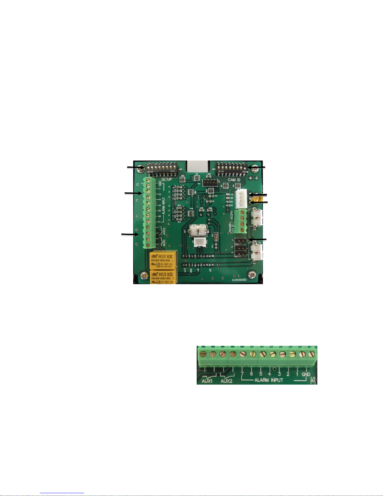
Alarm Relay Output “AUX1”
Alarm Relay Output “AUX2
Alarm Input GND
Alarm input signal -7
System Setup DIP Switch SW1
Dome Address DIP Switch SW2
Alarm Terminal 8P
Aux. Switch 4P
RS485 Terminal 2P
AC24V Power 1P
120Ω Resistance Short-Circuit
Pin
g. Only use a dry cloth to clean the camera. If there is dirt that is difficult to remove wipe
gently with a mild detergent. Never use strong or abrasive detergents.
h. The included 24VAC at 3A power supply must be used. Using a DC or other incorrect
power supply will damage the camera.
i. Only qualified installers are allowed to install, test and disassemble the camera.
j. The camera is a low voltage product. If installed outdoors proper safety and lightning
grounding are required.
k. Before installing be sure the grounding, wiring, input power, voltage, DIP switches,
communication protocol and baud rate are correctly set prior to powering up and using.
4. CAMERA SETUP
Address Set Up
See Appendix A for DIP Switch SW2 configurations for camera addresses.
Alarm Signal
V2.0 06/13/13
1, 2, 3, 4, 5, 6, 7 = Alarm Input Signal
AUX1, AUX2 = Auxiliary Equipment
GND = Alarm Input Grounding
Page 5
5
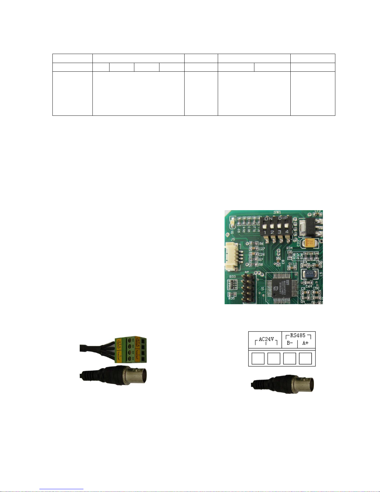
System Setup DIP Switch SW1 ON = 1 OFF = 0
Baud rate setting
DIP Switch
8 7 6 5 4 3 2
1
Function
DIP Switch 3, 2 =
00=2400
01=4800
10=9600
1. Power supply and
communication cable:
AC24V power supply
AC24V power RS485
2. Video output
ON and OFF are indicated on the DIP Switches to show the DIP positions.
PELCO-D and PELCO-P can be automatically recognized.
J7 pin = if jumpers 2-3 is short circuited, terminal connects to 120Ω resistance. If jumpers 1-2
short, terminal is not connected to 120Ω resistance.
To select the baud rate set switches 3 and 2 on the System Setup DIP Switch as described
above.
Camera Module Selection
The ST-PTZ550-27 uses the Samsung SDM-270
camera module although various other camera modules
may be compatible with the unit. The DIP switch
settings on the camera module’s PCB board are factory
set for the SDM-270 and are not to be adjusted by the
installer or user.
5. WIRING CONNECTIONS
a. Connect the power supply cable and communications cable to the AC24V and RS485
connections on the main board as shown above.
b. Connect the camera to the monitor with a 75 coaxial video cable.
c. Connect power supply’s AC plug to a suitable AC power outlet.
d. Make an RS485 connection between the camera and the PTZ controller. Ensure the
V2.0 06/13/13
connections at the PTZ controller and camera have the same polarities.
Page 6

6
High Speed Dome
Ver:2.20
PELCO D/P
BPS:2400
ID: 001
Tile Ref OK
Pan Ref OK
SONY FCB-EX480CP
6. FUNCTIONS and OPERATION
Function
Operation
Pan/Tilt
Move joystick to left, right, up, and down
Menu Confirmation
Press [OPEN]
Menu Cancellation
Press [CLOSE]
Zoom Out
Press [TELE] or rotate joystick clockwise for the desired image.
Zoom In
Press [WIDE] or rotate joystick counter clockwise for the desired image.
Focus Far
Press [FAR] until there is a clear image
Focus Near
Press [NEAR] until there is a clear image
Auto Focus
The dome is in the auto focus mode when the joystick is moved left, right, up, down or turned.
For manual focus press any key.
Enter Programming
Menu
Call preset 95 or user defined preset. Please refer to short-cut menu.
Return Zero Pan/Tilt
Point
Call preset 34 or user defined preset. Please refer to short-cut menu.
Start Pan Scan
Call preset 99 or user defined preset. Please refer to short-cut menu.
Auto Flip
Call preset 33 or user defined preset. Please refer to short-cut menu.
Pan Scan Limit
Left limit: Call preset 92 or a user-defined preset. Please refer to short-cut menu.
Right limit: Call preset 93 or a user-defined preset. Please refer to short-cut menu.
Call Tour 1
Call preset 96 or a user-defined preset. Please refer to short-cut menu.
Call Tour 2
Call preset 97 or a user-defined preset. Please refer to short-cut menu.
Call Tour 3
Call preset 98 or a user-defined preset. Please refer to short-cut menu.
Call Camera Mode 1
Call preset 100
Call Camera Mode 2
Call preset 101
Call Camera Mode 3
Call preset 102
Privacy Zone
Able to edit 4 areas as privacy zones to protect individual privacy. Please refer to
Basic Operation
After powering up the ST-PTZ550-27’s version number,
communication protocol, baud rate and address will be
shown on the monitor. At the same time, the system will
check the pan and tilt status and display the results. The
information will disappear once operations begin.
The table below is a quick guide to the camera’s basic operations using a PTZ Controller:
V2.0 06/13/13
Page 7

7
Camera ►
Pan ►
Shortcut Key ►
Self act
Nothing
Alarm Set ►
Degree
ON
Exposure ►
White Balance ►
Focus ►
Privacy ►
Other ►
Camera Model ►
Zoom Speed
5
Focus Speed
1
programming menu.
Privacy Zone
Press [FAR] to increase horizontal zones.
Press [NEAR] to reduce horizontal zones.
Press [TELE] to increase vertical zones.
Press [WIDE] to reduce vertical zones.
Indicates current working cursor
Indicates current activated cursor
►
Indicates there is a sub-menu after the current menu
Menu Operation
Call preset 95 to enter the menu setup. The main menu will be shown on the screen. Note the
following symbols:
The menu content is only changed under activated status. During menu operation the OPEN
key is used for confirmation and the CLOSE key is used for cancellation. The UP key is to move
the cursor up and the DOWN key is to move the cursor down.
Upon calling preset 95 the main menu screen may
appear as
Camera Sub-Menu
The quality of the target image is dependent upon the camera parameters set under the
camera menu. These parameters should be set to site-specific situations. The camera menu
will allow the control of exposure, white balance, privacy zones, digital zoon, infrared light
sensitivity, zoom speed, focus speed and other functions.
Under the main menu position the cursor to Camera
and press OPEN to enter the camera sub-menu and
set up the camera’s parameters.
Note that exposure, white balance, focus, privacy,
other and camera model have a sub-menu.
Zoom speed changes when activated.
Exposure
To maintain a clear image a suitable white balance and correct focus must be selected.
Further, the exposure must be properly controlled to ensure sufficient light. Under Exposure
press OPEN to enter the exposure sub-menu. The exposure sub-menu will display several
functions. Various functions have multiple settings.
V2.0 06/13/13
Page 8

8
Exp Mode
Auto
Shutter speed
6
Iris
15
Gain
1
Bright
15
BackLight
OFF
BackLight Val
0
Slow Shutter
OFF
Exp Mode
Auto
Shutter speed
6
Iris
15
Gain
1
Bright
15
BackLight
OFF
BackLight Val
0
Slow Shutter
OFF
Exposure ►
White Balance ►
Focus ►
Privacy ►
Other ►
Camera Model ►
Zoom Speed
5
Focus Speed
1
Exp Mode
AUTO
Shutter speed
6
Iris
15
Gain
1
Bright
15
BackLight
OFF
BackLight Val
0
Slow Shutter
OFF
Exp Mode Auto
Shutter Speed 6 (0 – 19)
Iris 15 (0 – 17)
Gain 1 (0 – 15)
Bright 15 (0 – 18)
Backlight OFF (ON/OFF)
Backlight Val 0
Slow Shutter OFF (ON/OFF)
To change exposure mode under “Exp Mode” press OPEN to enter the exposure mode
menu. Once done the menu becomes “Exp Mode”. Move the joystick up or down to change
the exposure modes.
Confirmation of an exposure mode selection –
Under “Exp Mode” press OPEN. The menu will
then turn to “Exp Mode”.
Cancellation of an exposure mode selection –
Under “Exp Mode” press CLOSE. The menu will
then turn to “Exp Mode”.
Exit Exposure Mode – “Exp Mode” press CLOSE
to exit the exposure mode and return to the main menu.
White Balance
White Balance (WB) is the process of removing unrealistic color casts so objects that appear
white in person are rendered white in the image. Proper camera white balance must take into
account the “color temperature” of a light source – the relative warmth or coolness of a light
source. The camera offers the option of AUTO white balance or MANUAL white balance.
V2.0 06/13/13
For other exposure mode operations under “Exp
Mode” move the joystick up or down. The symbol
will move to the relative menu to show the current
menu can be operated. Upon pressing OPEN to
activate a menu the symbol will appear before the
selected menu. Then move the joystick up or down
the change the menu setup. Press OPEN to confirm
the changes or CLOSE to cancel. Once completed
the symbol will appear before the menu.
Under ”White Balance” press OPEN to enter the
white balance sub-menu.
Page 9

9
Privacy1
Privacy2
Privacy3
Privacy4
WB mode
Auto
R Gain
210
B Gain
175
Exposure ►
White Balance ►
Focus ►
Privacy ►
Other ►
Camera Model ►
Zoom Speed
5
Focus Speed
1
White Balance Auto
R Gain 210 (0 – 255)
B Gain 175 (0 – 255)
For WB Mode Setup – Under ”WB mode” press OPEN to activate the WB mode menu after
which the menu turns to “WB mode”. Move the joystick up or down to change the setup.
The order of parameters on the right will be Auto, Manual, Outdoor, Indoor, ATW and OPW.
For R Gain Setup – Under ”WB mode” move the joystick down to “R Gain” and press OPEN
to enter the R Gain setup. Then move the joystick up or down to adjust the R Gain values from
0 to 255. Once the value has been selected press OPEN to confirm or CLOSE to cancel.
For B Gain Setup – Under ”WB mode” move the joystick down to “B Gain” and press OPEN
to enter the B Gain setup. Then move the joystick up or down to adjust the B Gain values from
0 to 255. Once the value has been selected press OPEN to confirm or CLOSE to cancel.
Privacy
To protect certain areas (e.g., a password input area or a manager’s work area) there may be a
need to mask those areas from surveillance. Under “Exposure ►” move the joystick down to
the privacy menu. Press OPEN to enter the privacy sub-menu to set up the parameters.
There are 4 privacy zones: Privacy1, Privacy2, Privacy3, Privacy4.
The following PTZ Controller function keys are used to set privacy zone parameters:
OPEN – Confirmation
CLOSE – Cancellation
FAR – Increase Horizontal Area
NEAR – Reduce Horizontal Area
TELE – Increase Vertical Area
WIDE – Reduce Vertical Area
Under the privacy sub-menu press OPEN to adjust the privacy zones using the above
function keys. Press OPEN to confirm the previous setup.
V2.0 06/13/13
Page 10

10
Camera Mode Save:
Normal
Day
Night
Camera Mode Exec:
Normal
Day
Night
Digital Zoom
ON
Auto ICR
OFF
ICR
OFF
Display
OFF
Camera Mode Save:
Normal
Day
Night
Camera Mode Exec:
Normal
Day
Night
Digital Zoom ON (ON/OFF)
Auto ICR OFF (Auto ICR ON/OFF)
ICR OFF (Manual ICR ON/OFF)
Display OFF (Camera Info ON/OFF)
Camera Mode Save Save Camera Mode
Camera Mode Exec Call saved Camera Mode
Normal Mode 1 (Standard)
Day Mode 2 (Day)
Night Mode 3 (Night)
To cancel privacy zones – There are two options: (a) restart the camera or (b) decide which
privacy zone(s) is to be cancelled. Then enter the relative privacy zone menu, press OPEN to
enter the menu, the press CLOSE to cancel the relative privacy zone when the above menu
appears.
Other
To access an Other sub-menu move the joystick to the desired sub-menu. Once selected the
current sub-menu press OPEN then move the joystick up or down to select the desired
parameters. Press OPEN to confirm the selection or CLOSE to cancel.
Camera Mode
The Camera Mode is used to set various camera settings for the ambient environment. Given
the ambient environment may be changing (e.g., day and night) the unit allows the user to
create and recall specific settings to easily manage changing conditions. Under the Camera
Mode menu press OPEN to enter the camera mode setup menu.
and exit.
Camera modes can be selected by calling certain presets:
V2.0 06/13/13
The 3 menus under “Camera Mode Save” are
previous saved camera modes. Move the cursor to
a camera mode and press OPEN. will change to
and return to after 1 second after which the
camera mode is successfully saved.
There are 3 saved camera modes for calling under
“Camera Mode Exec”. The order is the same as
that of “Camera Mode Save”. Move the cursor to a
certain camera mode then press OPEN to confirm
Page 11

11
NORMAL – call preset 100
Home Place OFF (ON/OFF, 1 – 32)
Leisure Time 30
AS Speed 20 Auto Pan Speed (0 – 80)
PS1 Speed 100 Tour 1 Speed (100 – 120)
PS1 Time 5 Tour 1 Leisure Time (5 – 120)
PS2 Speed 100 Tour 2 Speed (100 – 120)
PS2 Time 5 Tour 2 Leisure Time (5 – 120)
PS3 Speed 100 Tour 3 Speed (100 – 120)
PS3 Time 5 Tour 3 Leisure Time (5 – 120)
Auto Flip ON (ON/OFF)
Home place
OFF
Leisure Time
30
AS speed
20
PS1 Speed
100
PS1 time
5
PS2 Speed
100
PS2 time
5
PS3 Speed
100
PS3 time
5
Auto Flip
ON
DAY – call preset 101
NIGHT – call preset 102.
NORMAL is the default mode.
Zoom Speed
Under the Exposure sub-menu move the cursor to “Zoom Speed” and press OPEN and change
the parameters after the symbol turns to . Then press OPEN to confirm or CLOSE to
cancel after which the symbol will return to .
Focus Speed
Under the Exposure sub-menu move the cursor to “Focus Speed” and press OPEN and
change the parameters after the symbol turns to . Then press OPEN to confirm or CLOSE
to cancel after which the symbol will return to .
Pan
The Pan Menu is found under the Main Menu. Through the Pan Menu users can open and
close a home position, adjust auto pan speed, set the tour speed and dwell time and open and
close auto flip.
Shortcut Key
V2.0 06/13/13
Page 12

12
The Shortcut Key Menu is found under the Main Menu. Shortcut keys allow the association of a
Nothing Without self act
Home Home Place
A Scan Auto Scan
P Scan 3 Tour 3
P Scan 2 Tour 2
P Scan 1 Tour 1
Open Menu Opens the menu
Auto Flip Auto Flip
Reference Zero Point
Left Limit Left Limit
Right Limit Right Limit
Preset scan 1 Tour 1
Preset scan 2 Tour 2
Preset scan 3 Tour 3
Auto Scan Auto Scan
Open Menu
95
Auto Flip
33
Reference
34
Left Limit
92
Right Limit
93
Preset scan 1
96
Preset scan 2
97
Preset scan 3
98
Auto scan
99
Camera ►
Pan ►
Shortcut Key
Self act
Nothing
Leisure Time
030
Alarm Set ►
Degree
ON
certain function with a corresponding preset allowing for quick and convenient function
selection.
The values in the above menu are defaults. When new values are specified as shortcut
keys the default values are still effective. For example, if the user specifies 16 as the
shortcut key to open menu, the menu still can be opened by calling preset 16 and 95.
Tour 1 includes preset 1 – 8; Tour 2 includes preset 9 – 16 and Tour 3 includes preset 17 – 24.
If there are missing presets in one tour the system will re-scan from the first preset. If the first
preset was not set the system will exit the tour.
Newly set values should not be the same with any of the above shortcut preset values.
To set shortcut keys move the cursor to the desired menu item and press OPEN. The
symbol turns to . The parameters can now be changed. Press OPEN to confirm or CLOSE to
cancel. The symbol will return to .
Self Act
After the camera performs its self-check the unit operates according to this menu. The starting
time is determined by the set Leisure Time.
The Self Act Menu is found under the Main Menu. Move the cursor to “Self act” and press
OPEN. The symbol turns to . The parameters can now be changed. Press OPEN to
confirm or CLOSE to cancel. The symbol will return to .
Leisure Time
V2.0 06/13/13
Page 13

13
Camera ►
Pan ►
Shortcut Key
Self act
Nothing
Leisure Time
030
Alarm Set ►
Degree
ON
If the Leisure Time reached the previous set value after manual operation the unit will
Camera ►
Pan ►
Shortcut Key
Self act
Nothing
Leisure Time
030
Alarm Set ►
Degree
ON
Alarm1 mode
CLOSE
Alarm2 mode
CLOSE
Alarm3 mode
CLOSE
Alarm4 mode
CLOSE
Alarm5 mode
CLOSE
Alarm6 mode
CLOSEF
Alarm7 mode
CLOSE
Alarm1 set
AUX1
Alarm2 set
AUX1
Alarm3 set
AUX1
Alarm4 set
AUX1
Alarm5 set
AUX1
automatically run according to Self Act (except when Self Act is set to “Noting”). If the
parameter in Self Act is “Home Place” the user must ensure that “Home Place” is on.
The value of Leisure Time can be set from 1 to 240.
The Leisure Time Menu is found under the Main
Menu. Move the cursor to “Leisure Time” and press
OPEN. The symbol turns to . The parameters
can now be changed. Press OPEN to confirm or
CLOSE to cancel. The symbol will return to .
Alarm Set
Through Alarm Set the user can set the alarm mode and relay output. The Alarm Set Menu is
found under the Main Menu. Move the cursor to “Alarm Set” and press OPEN to enter the
sub-menu. Move the joystick up or down to enter additional menu pages.
Parameters for Alarm Mode are either OPEN or CLOSE.
Parameters for AlarmXSet are AUX1(AUX2) Alarm Output Set AUX1 (AUX2)
Alarm Mode CLOSE = The alarm works when the alarm input terminal and GND are open
circuited. The AUX 1 relay is closed when there is an alarm and opened when there are no
alarms. The setup of AUX2 is the same as AUX1.
Alarm Mode OPEN = The alarm works when the alarm input terminal and GND are
short-circuited. The AUX 1 relay is open when there is an alarm and closed when there are no
alarms. The setup of AUX2 is the same as AUX1.
Note: The maximum relay output is 24VAC @1A.
Once in the Alarm Mode/Alarm Set Sub-Menu press OPEN. The symbol turns to . The
V2.0 06/13/13
Page 14

14
parameters can now be changed. Press OPEN to confirm or CLOSE to cancel. The symbol
will return to .
Degree
The Degree Menu is found under the Main Menu and is used to display the pan degree on the
monitor. Move the cursor to Degree and press OPEN. The symbol turns to . The
parameters can now be changed to OFF or ON. Press OPEN to confirm or CLOSE to cancel.
7. TROUBLESHOOTING
a. No picture after applying power – (i) check all plugs and cables are securely connected
to the proper connectors; (ii) ensure your power supply is providing the correct voltage
and current.
b. The picture has ripples – (i) check to see if the power supply is experiencing AC ripple,
if so a filter may be required; (ii) determine if the monitor is faulty; (iii) determine if other
peripheral equipment is causing ripple and if so make the necessary adjustments.
c. The picture background continuously changes color – a fluorescent lamp’s magnetic
field may cause color roll, therefore, reduce the number of fluorescent lamps or
increase the distance between the camera and the lamps.
d. The picture appears smeared – (i) the power supply voltage level may be unstable,
therefore, try another power supply; (ii) ensure the cables are correctly connected
and/or the cables are of the correct impedance.
e. Other interference may require a SecurityTronix ground loop isolation filter.
f. Power is on, but the controller does not work – (i) check to make sure the DIP switches
for address and communications baud rate are properly set, (ii) check to ensure the
RS485 connections at the camera and the PTZ Controller have the same polarity, (iii)
check the integrity and continuity of the unshielded twisted pair (UTP) control cable.
g. Additional troubleshooting assistance can be found on-line at www.securitytronix.com
in addition to support from SecurityTronix sales engineers at 1-610-429-1511.
APPENDIX A
CAMERA ADDRESS SETTING USING 8-DIGIT DIP SWITCH SW2
V2.0 06/13/13
Page 15

15
CAM ID
8 7 6 5 4 3 2
1
1
OFF
OFF
OFF
OFF
OFF
OFF
OFF
ON 2 OFF
OFF
OFF
OFF
OFF
OFF
ON
OFF
3
OFF
OFF
OFF
OFF
OFF
OFF
ON
ON
4
OFF
OFF
OFF
OFF
OFF
ON
OFF
OFF
5
OFF
OFF
OFF
OFF
OFF
ON
OFF
ON 6 OFF
OFF
OFF
OFF
OFF
ON
ON
OFF
7
OFF
OFF
OFF
OFF
OFF
ON
ON
ON
8
OFF
OFF
OFF
OFF
ON
OFF
OFF
OFF
9
OFF
OFF
OFF
OFF
ON
OFF
OFF
ON
10
OFF
OFF
OFF
OFF
ON
OFF
ON
OFF
11
OFF
OFF
OFF
OFF
ON
OFF
ON
ON
12
OFF
OFF
OFF
OFF
ON
ON
OFF
OFF
13
OFF
OFF
OFF
OFF
ON
ON
OFF
ON
14
OFF
OFF
OFF
OFF
ON
ON
ON
OFF
15
OFF
OFF
OFF
OFF
ON
ON
ON
ON
16
OFF
OFF
OFF
ON
OFF
OFF
OFF
OFF
17
OFF
OFF
OFF
ON
OFF
OFF
OFF
ON
18
OFF
OFF
OFF
ON
OFF
OFF
ON
OFF
19
OFF
OFF
OFF
ON
OFF
OFF
ON
ON
20
OFF
OFF
OFF
ON
OFF
ON
OFF
OFF
∶
∶
∶
128
ON
OFF
OFF
OFF
OFF
OFF
OFF
OFF
129
ON
OFF
OFF
OFF
OFF
OFF
OFF
ON
130
ON
OFF
OFF
OFF
OFF
OFF
ON
OFF
131
ON
OFF
OFF
OFF
OFF
OFF
ON
ON
132
ON
OFF
OFF
OFF
OFF
ON
OFF
OFF
133
ON
OFF
OFF
OFF
OFF
ON
OFF
ON
134
ON
OFF
OFF
OFF
OFF
ON
ON
OFF
∶
∶
∶
250
ON
ON
ON
ON
ON
OFF
ON
OFF
251
ON
ON
ON
ON
ON
OFF
ON
ON
252
ON
ON
ON
ON
ON
ON
OFF
OFF
253
ON
ON
ON
ON
ON
ON
OFF
ON
254
ON
ON
ON
ON
ON
ON
ON
OFF
255
ON
ON
ON
ON
ON
ON
ON
ON
V2.0 06/13/13
 Loading...