

Page 1

ST-IP-MD36-1
ST-IP-MD36-2
HD Mini Network Dome Camera Quick Start Guide
Version 1.0.0
Page 2

2
Welcome
Thank you for purchasing our Network camera.
This Quick Start Guide is designed to get your system up and running as easily as possible.
This document applies to bot h t he ST-IP-MD36-1 and ST-IP-MD36-2 camera models (1mp &
2mp).
Please read the following saf eguard and warnings carefully before you use this camera.
Please keep this document for future reference.
Important Safeguards and Warnings
1.Electrical safety
All installation and operation should conform to your local elect rical safety codes.
The power shall conform to the r equirement in the SELV (Safety Extra Low Voltage) and the
Limited power source is rated 12V DC, DC5V or AC24V in the I EC60950-1. (Power supply
requirement is subject to the device label).
Please prevent the line cor d from being crushed or damaged, especially at the plug, power
socket and the junction from the device.
Note: Do not connect a PoE power source AND a power supply to the device at t he same
time; it may result in device damage.
We assume no liability or responsibility for fires or electrical shoc k caused by improper
handling or installation.
We are not liable for any problems caused by unauthorized modification or attempted repair.
2.Environment
Don’t aim the device at strong light (s uch as lighting, sunlight and so on) to focus;
otherwise it may cause overexposure, which will affect the lon gevity of the CCD or CMOS
imager.
Please transport, use and stor e t he device within the range of allowe d humidity and temperature.
Don’t keep the device in a place which is wet, dusty, extremely hot , and ext r emely cold and with
strong electromagnetic radiation or unstable lighting.
Please do not allow water and ot her l iquids to enter the camera, to pr event the internal
components from being damaged.
Please allow adequate ventilation around the camer a t o pr event heat accumulation.
Please pack the device with the standard factory packaging or material with the same
quality when transporting the device.
Avoid bumps and humidity during transportation, stor age and installation.
Page 3

3
3. Operation and Daily Maintenance
Please do not dismantle the dev ice; Doing so may void your warr ant y.
It is recommended to use this camera with a surge-protection device.
The grounding holes of th e pr oduct ar e r ecommended to be grounded to further enhance the
reliability of the camera.
Do not touch the CCD (CMOS) optic component directly. You can use an air blower to clean
the dust or dirt on the lens surface. Pl ease use a dry cloth wetted by alcohol t o wipe away the
dust gently if it is necessary to clean.
Always use a dry, soft cloth to clea n t he device. If there is too much dust, pl ease use the water to
dilute mild detergent first and then use it to clean the device. Finally use the dry cloth to clean the
device. Don’t use volatile solvents like alcohol, benzene, thin ner etc or strong detergents with
abrasiveness, otherwise it will damage the surface coating or reduce the working performance of
the device.
The dome cover is an optical devi c e, ple as e don’t touch or wipe cover surface directly during
installation and use, pleas e r efer t o t he following methods to clean a d irt y lens:
Stained with dirt:
Use an oil-free soft brush to gent ly remove it.
Stained with grease or fingerprints:
Use a soft cloth to wipe the dome gently to dry it, then use oil-free cotton cloth or paper soaked
with alcohol or detergent to wipe from the lens center to outward. It is ok to change the cloth and
wipe several times to get all o f the dirt off.
Warning
Please use the standard accessories provided by SecurityTronix and make sure the device is
installed and repaired by pr of essional engineers.
Please do not provide two or more power supply modes for the dev ice, otherwise it may cause
damage to the device.
Statement
Please refer to the actual product for more det ails; this manual is just for reference.
Please contact the supplier or cus t om er ser vice if there is any problem occur red when using the
device.
Please contact the custo mer service for the latest proced ur e and supplementary docume nt ation.
There may be deviation between the actual value of some data an d t he value provided in the
manual due to the reasons such as t he r eal environment is not stab le and so on. Please refer to
the company’s final explanat io n if there is any doubt or dispute.
Page 4
4
The company is not liable for any loss caused by operation which is inconsistent with the
instructions in the manual.
Note:
Please refer to the disk for more details. Check and download corresp onding user ’s manuals
and tools from the SecurityTronix website: http://www.securitytronix.com/support/
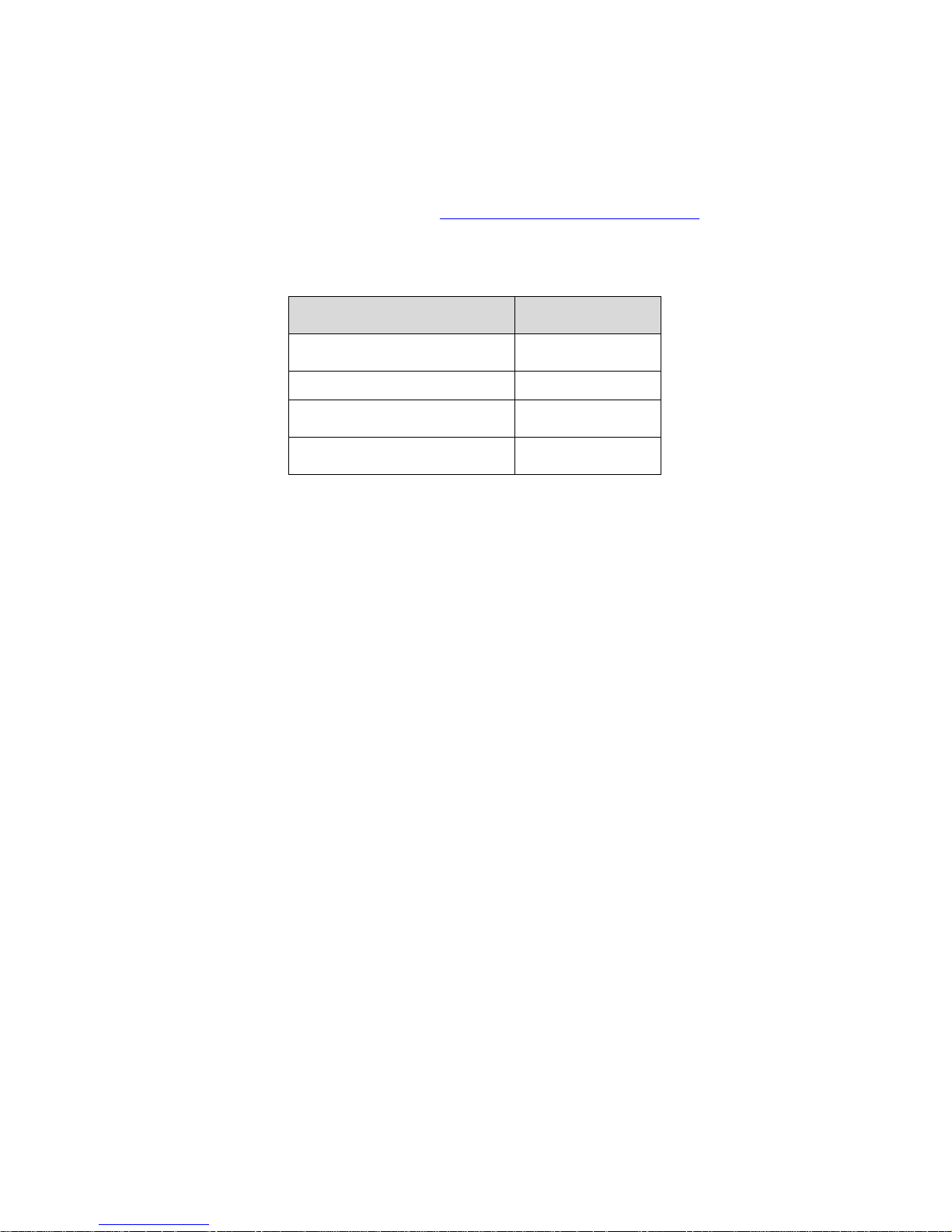
Before installation, plea se open the package and ensure all the components are included.
Contact your local retailer ASAP if something is broken in y our package.
Accessory Name Amount
Network Camera Unit
1
Installation Accessories bag
1
Quick Start Guide
1
CD
1
Page 5

5
Table of Contents
1
Framework......................................................................................................................... 5
1.1
Structure .............................................................................................................. 5
1.2
Dimensions .......................................................................................................... 6
2
Installation ......................................................................................................................... 8
2.1
Device Installation .............................................................................................. 8
2.2
Micro SD Card Installation ................................................................................ 9
3
Network Configuration ................................................................................................... 11
3.1
Modify IP Address ............................................................................................ 11
3.2
Login WEB Interface ........................................................................................ 12
Page 6

6
1
Physical Properties
1.1 Structure
Note:
The following diagram is for reference only, to illustrate the device component and cable port
functions.
Device component and cable port function may differ accor di ng to different models, please refer
to the actual device for details.
Figure 1-1
Please refer to the following she et for detailed structure information.
Component
Component name
1 X-Y-Z rotation module
2 Device lens
3 Dome camera enclosure
Please refer to the following she et for detailed port information.
Port Port name Function
4
Power input port
Connect to a 12VDC pow er s upply
Page 7

7
5
Network port
Network data input, output and
PoE.
Note:
Some devices do not support
PoE.
6 MIC hole Audio input
1.2 Dimensions
Please refer to the following figure for the dimension information. Dimensions are listed in
millimeters. See Figure 1-1 through Figure 1-3.
Figure 1-1 Dimension illustration 1
Figure 1-2 Dimension illustration 2
Page 8

8
Figure 1-3 Dimension illustration 3
Page 9

9
2
Installation
2.1 Device Installation
Figure 2-1 Device installation illustration 1
Important
Please make sure the inst al l at i on surface can support at least 3 times the weight of the
camera and the bracket.
Please refer to the steps listed below.
Step1
Use the inner hexagonal wr ench ( pr ovided) to loosen the three i nner hexagon screws in the
outer dome cover and then rem ove the cover.
Step 2
Locate the installation template in the accessories bag, and affix it to t he c eiling or wall
according to your monitor area requirements.
Step 3
Drill 3 holes, 3/16” diameter as indicated at the marks on the template. Remove the templat e
and insert the 3 included plastic expansion anchors in the holes.
Note:
If the cable must exit behind the installation surface (behind a wall or inside the ceiling),
Drill a ¾” cable exit hole in the mounting surface according to t he installation template.
If the cable must exit the camera on the surface of the wall or ceilin g, use a strong needle-
nose plier or similar tool to pr y out and remove the thin metal of the camera’s outer shell, as
shown in Figure 2-1 above; “Remove this for surface-cable use”.
Remove this for surface-cable use
Page 10

1
Step 4
Adjust the base of the camera to the proper position and t hen pull the cable t hr ough the cable
exit hole drilled earlier in the ceiling or wall. Line up the TOP d irect ion of the device to the
installation template and then line up the three screw holes in the camera’s base to the three
plastic anchors in the mounting surface. Install the thr ee self-tapping screws firmly into the
anchors.
Step 5
Use the ‘inner hexagonal w r ench’ to loosen the two screws which sec ure the lens rotation
structure NOTE: Do not remove these screws. Only loosen them enough for the camera
housing to move freely to the correct viewing position. Adjust the lens to the required
viewing angle, then secure the screws of the lens rotation structure. The lens adj ust angle
ranges are: flip (0°~+75°), video pan rotation (-15°~+15°) , video rotation angle (-15°~+15°).
Figure 2-2 Device installation illustration 2
Step 6
Line up the dome camera cover t o the cable exits and reinstall the cov er. Use the inner
hexagonal wrench to secur e the three inner hexagonal screws firmly.
Note:
If you want to restore the factory default settings of the camera, r em ove the outer cover and
press and hold the Reset button in Figure 2-2 with power on for 10s.
2.2 Micro SD Card Installation
Note:
This model of camera does not suppor t M icro SD card functions.
Step 1
Open the camera by referring to step 1 in chapter 2.1 device installation.
Step 2
Find the “Micro SD CARD” mark on the inner cover, adjust the direction of Micro SD card and
complete installation according to the l oc ation shown in the Figure 3-3.
Page 11

10
Step 3
Please complete the oper at ion by referring to step 6 in chapter 2. 1 device installation.
Figure 2-3
Page 12

11
3
Network Configuration
The IP address of each ca mera is the same when leaving t he SecurityTronix factory (default
IP192.168.1.108). For the sm oot hest project installation, please allocate a useable IP segment
of the entire network accor ding to t he actual network environment.
3.1 Modify IP Address
IP address can be acquired and modified through the quick configuration tool for the cameras
which is accessed via a wired network; Cameras m ust connect via a wired network to configure
wireless parameters before using wireless network cameras. This chapter will introduce the
approach of modifying IP addresses via the “Quick Configuration Tool”. You can also modify th e
IP address in the network parameters of the WEB interface. Please refer to the documen t in the
disk << WEB Operation Manua l> > for more details.
NOTE:
Currently the quick configuration tool only supports cameras which are addressed w it hin the
same network segment (subnet ) as t he computer’s IP address.
Step 1 Double click the “ConfigTools.exe” and open the quick configuration tool.
Step 2 Double click the device to be configured, and the “Login” dialog box will appear. Enter the
IP address, user name, passwor d and port number of the camera, and click “Confirm”.
Note:
The default user name and passw ord are admin and admin respectively. The default por t number
is 37777. See Figure 3-1 for more details.
Page 13

12
Figure 3-1
Step 3 Modify the camera I P address on the “Net” interface, click “Save” to finish modification.
See Figure 3-2 for more details.
Figure 3-2
3.2 Login WEB Interface
Note:
Different devices may have different WEB interfaces, the figures below are just for reference,
please refer to the document <<WEB Operation Manual>> in the disk and the actual interface for
more details
Step 1 Open IE and input the modi f ied camera IP address in the address bar.
Step 2 The login interface is show n below, please input your user na me an d password (Default
user name is admin and passwor d i s admin respectively), click “login”.
See Figure 3-3 for more details.
Page 14

13
Figure 3-3
Step 3 Install controls according to the system prompt; see Figure 3-4 for the WEB main
interface. Please modify the administrator password as soon as possible after you successfully
logged in.
Figure 3-4
Page 15

14
Note
• This quick start guide is for r ef erence only. Slight difference may be found in the
user interface.
• All the designs and softwar e here are subject to change without prior written
notice.
• Please visit our website or co ntact your local service engineer for more
information.
SecurityTronix offers live, human tech support for our products 24 hours a day, 7 days a week,
365 day a year.
Technical support contact info:
Phone: (610) 688-9282 Option #3, then #2
Email: support@securitytronix.com
Web: www.securitytronix.com/support
SecurityTronix
1085 Andrew Dr. Ste A
West Chester, PA 19380
 Loading...