

Page 1
Thank you for purchasing our Network camera. This Quick Start
Guide is designed as a tool to help you get started as quickly as
possible. Detailed operation instructions are included on the
enclosed CD. Please keep this guide for future reference. Please
check the contents of the camera box to ensure that all items are
present as listed in the “included items” list below. Contact
SecurityTronix immediately if anything is missing or if there is
damage to the camera
Introduction
1. Electrical safety
All installation and operation of this camera should conform to
your local and national electrical safety codes.
The power shall conform to the requirements in the SELV (Safety
Extra Low Voltage) and the limited power source is rated 12V DC or
24V AC in the IEC60950-1. (Refer to the general introduction).
Please Note: Do not connect two power supply sources to the
device at the same time; it may result in damage to the device.
SecurityTronix assumes no liability or responsibility for improper
handling or installation, or unauthorized modication or
attempted repair, which could result in re, electrical shock or
physical harm to persons involved.
2. Physical considerations
Keep the camera free of any harsh physical impact, before, during
and after installation. Do not allow water to penetrate the case
during installation and ensure that all weatherproof seals are
properly in place to keep water out during normal operation.
3. Installation
Do not apply power to the camera until installation has been
completed and all wires have been run and are protected from
physical damage. Ensure there is a means to quickly disengage
power from the camera in the event of a short circuit.
4. Qualied Operators
All examination, installation and operation of the camera should be
performed by persons qualied for such work. SecurityTronix in not
liable for any damage to persons or property caused by improper
installation, unauthorized modications or attempted repairs to
the camera.
5. Environment
This series of network camera is designed to be installed in an
Important Safeguards and Warnings
THE IMAGE OF QUALITY
TRONIX
SECURITY
®
HD Mini IR Waterproof Fixed Lens
720P (1.3MP) Network Camera
Quick Start Guide Version 1.0
D
A
T
A
T
R
O
N
I
X
C
A
B
L
E
T
R
O
N
I
X
S
E
C
U
R
I
T
Y
T
R
O
N
I
X
F
I
B
E
R
T
R
O
N
I
X
S
N
G
I
S
E
D
C
I
N
O
H
P
M
Y
S
NACE BRANDS
®
environment free of strong, local electromagsusceptible to direct
beams of laser light, such as retail scanners. Lightning surge
suppressors are highly recommended to further help protect the
camera from high voltage discharges.
6. Maintenance
Use only a soft, lint-free cloth and mild detergent to clean the exterior
of the camera. Dome cameras have a plastic-based optical dome;
special care should be taken to use only cleansers which will not
scratch or cloud the plastic.
7. Accessories
Be sure to use only accessories made for or approved for this model of
camera. If you have any questions, contact SecurityTronix at (610)
429-1821, press 3, then 2.
Important Safeguards and Warnings
Package Contents:
1 Network Camera
1Quick Start Guide
1 Installation Hardware
1 Software CD
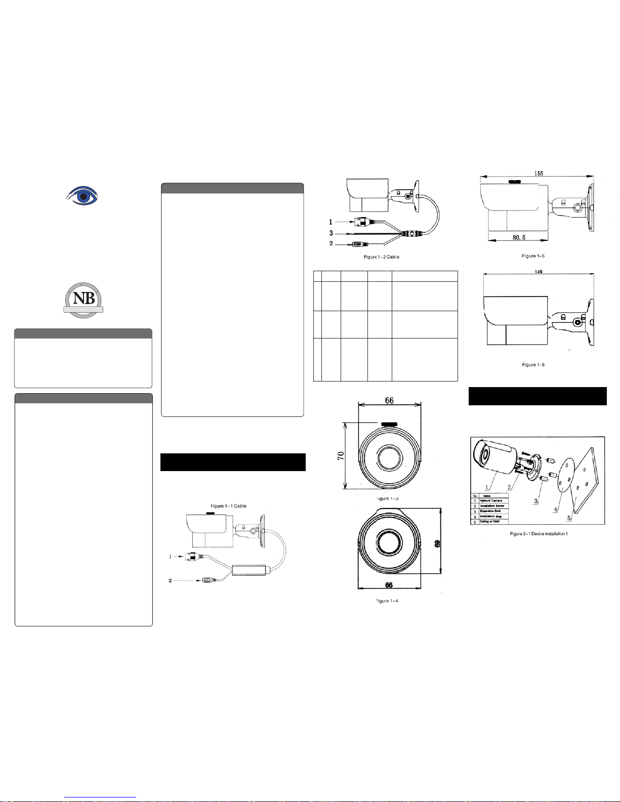
1.1 Cable
Please refer to the following diagrams for cable
identication of the camera
#
1
2
3
Port Function Type Note
LAN Network Ethernet Connect to standard
Port Port ethernet cable.
NOTE: Some devices
do not support PoE.
DC 12V
Power
input
5.5mm
barrel
Minimum current
required is 1A
(1,000mA). Connector
is center-positive.
Reset
WPS reset
Bare
wires
Used to initiate WPS
connections by connecting
the wires for 2 seconds.
Keeping the wires together
for 5 seconds or longer will
reset the defualt IP address
1
Mechanical Description
2
Device Installation
ST-IP-BT3.6-1
Page 2
Step 1.
Adhere the mounting template to the surface
on which the camera will be installed.
Step 2.
Drill 3 holes in the wall or ceiling, using
the template as a guide.
Step 3.
Remove the template and Insert the 3
included plastic anchors into the 3 holes.
Step 4.
Use the 3 included screws to mount the camera
into the anchors.
Step 5. Connect the cables to the camera.
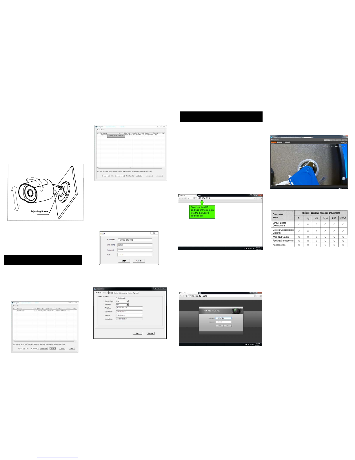
Step 6. Loosen the phillips-head adjusting
screw, aim the camera and retighten the
adjustment screw.
3.1 Overview
The Quick Conguration Tool can discover the cameras
on the network, display the IP addreses and allow the
user to modify the addresses.
3.2 Operation
Double-click the “congtools.exe” icon and the
interface shown below will be displayed.
Select an IP address, right-click the mouse and a
pop-up menu will be displayed as shown below.
Click “OPEN DEVICE WEB” to log in to the camera
using a web browser.
The camera can be readdressed without logging
in via a web browser. From the Conguration
tool’s main interface (see gure 3-2), click on the
camera to re-address and then click the “Login”
button. The Login screen will appear, as shown
below in gure 3-3.
Verify that the information correct for the camera
and click “Login”.
Once logged in, the Conguration Tool main
interface appears as shown below in gure 3-4
For detailed instruction of the Quick Conguration
Tool, please refer to the manual for it on the included
resource CD
This IP camera supports web access and management
via a PC.
The web interface includes several modules; monitor
channel preview, System conguration, Alarm, etc.
4.1 Network Connection
Follow the steps below for network connection.
* Ensure the camera is powered, physically connected to
the network and is assigned an IP address within the
range of the LAN’s subnet.
4.2 Login and Main Interface
Open Microsoft Internet explorer and input the camera’s
IP address in the browser’s address bar.
The login interface is shown below in gure 4-2. Enter
the user name and login password. The factory default
user is “admin” and the password is also “admin”. For
security, please change the password after logging in.
After successfully logging in, you will be prompted
to install the web plug-in for viewing the camera.
Please refer to the Web Operation Manual included
in the resource CD for detailed operation instructions.
3
Quick Conguration Tool
4
Web Operation
Figure 2-2 Device Installation
Figure 3-1 Search Interface
Figure 3-2 Search Interface 2
Figure 3-3 Login Prompt
Figure 3-4 Quick Conguration
Figure 4-1
Figure 4-2
Figure 4-3
APPENDIX - Toxic or Hazardous Materials or Elements
This Quick Start Guide is designed as
a tool to provide the essential info
information needed to quickly get
this IP camera online as easily as
possible.
Full documentation for the camera,
Quick Conguration Tool, and web
operation of the camera can be found
on the included CD.
For award-winning technical
assistance, please call SecurityTronix
at: (910) 429-1821
visit us at: securityTronix.com
or email us at:
support@securitytronix.com
 Loading...