

Page 1
ST-HVR8704
ST-HVR8708
ST-HVR8716
Professional Digital Video Recorders
QUICK START GUIDE
1
Page 2
16 ch HVR shown. Instructions also apply to 4ch and 8ch HVRs
Thank you for purchasing this SecurityTronix Hybrid Video Recorder!
The documentation for this HVR comes in 2 formats; this printed Quick
Start Guide and a full installation manual in PDF format on the included
DVD disc. The full manual is also available online at:
http://www.securitytronix.com/products/products.php?cat=HVR
This quick start guide covers the most essential information for getting
the HVR up and running:
Making connections and powering up.
Logging into the HVR menus.
Setting the time and Date.
Setting the HVR to record 24/7.
Making network connections and remote access.
MAKING CONNECTIONS
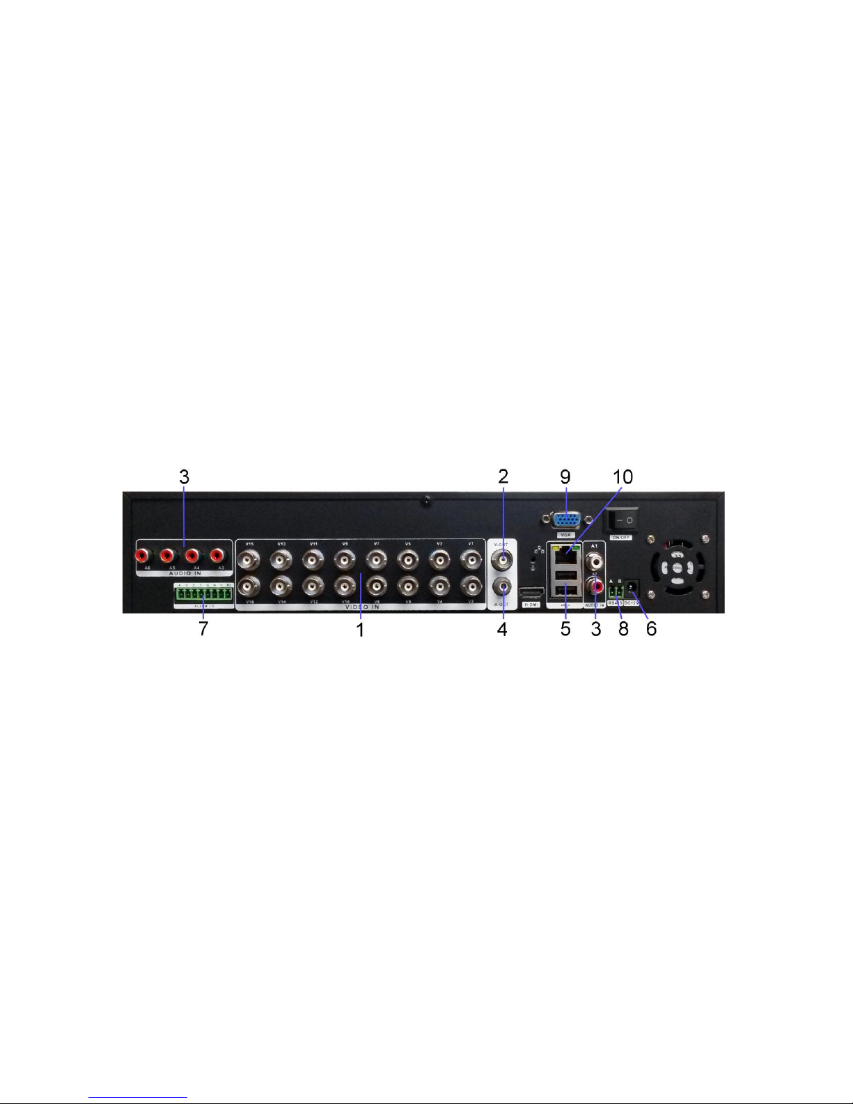
There are 3 connection types which MUST be made to use the HVR:
1) Up to 16 BNC video inputs from cameras (#1 in the image
above).
2) Power for the HVR. Use the supplied 12VDC power supply (#6
in the image above).
3) Monitor output. Either the BNC connection (composite video, # 2
above) or the VGA connection (RGB video #9 above). VGA is
the recommended output.
It is also strongly recommended to use the included USB mouse via the
rear panel USB connection (#5). An Ethernet connection (#10) will also
be needed for remote viewing of the HVR.
2
Page 3
POWERING ON and SHUTTING DOWN
Powering On
a. Plug the 12 volt DC connector of the included power
supply into the HVR’s power port. Then plug the AC
plug into an appropriate AC power outlet which supplies
between 110 and 127 volts AC.
b. Once there is power to the HVR the POWER indicator
light will be displayed on the HVR’s front panel. The
HVR will beep after startup.
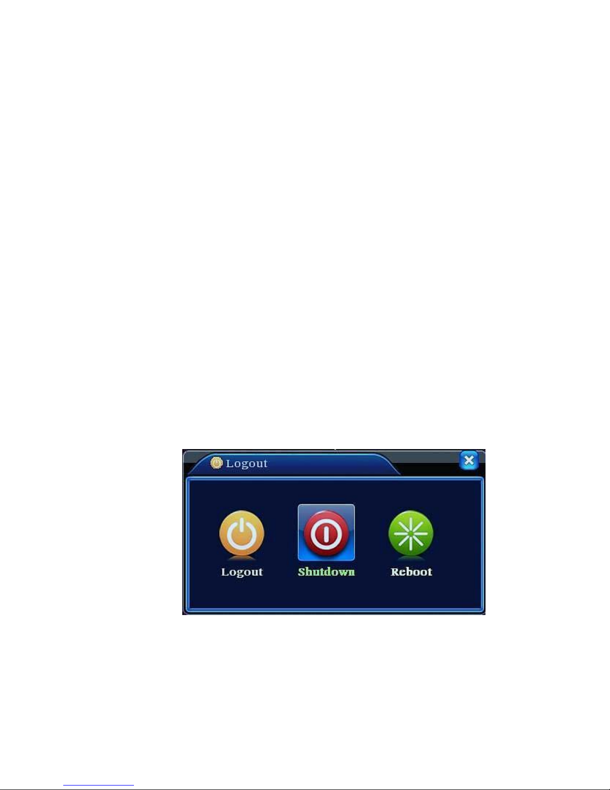
Shutting Down
There are two methods for shutting down the HVR:
a. Enter the MAIN MENU select LOGOUT then select
SHUTDOWN or right-click the mouse and from the
Short-cut Menu select LOGOUT followed by
SHUTDOWN. Note the user must be logged in to shut
down the HVR. A Logout/Shutdown screen similar to the
one below is displayed.
b. Remove power to the unit by disconnecting the power
supply. This, however, should be avoided as doing so
may corrupt and/or damage the hard drive. Only remove
power from the unit if the HVR will not respond to a
shutdown through the Main Menu as described above.
3
Page 4
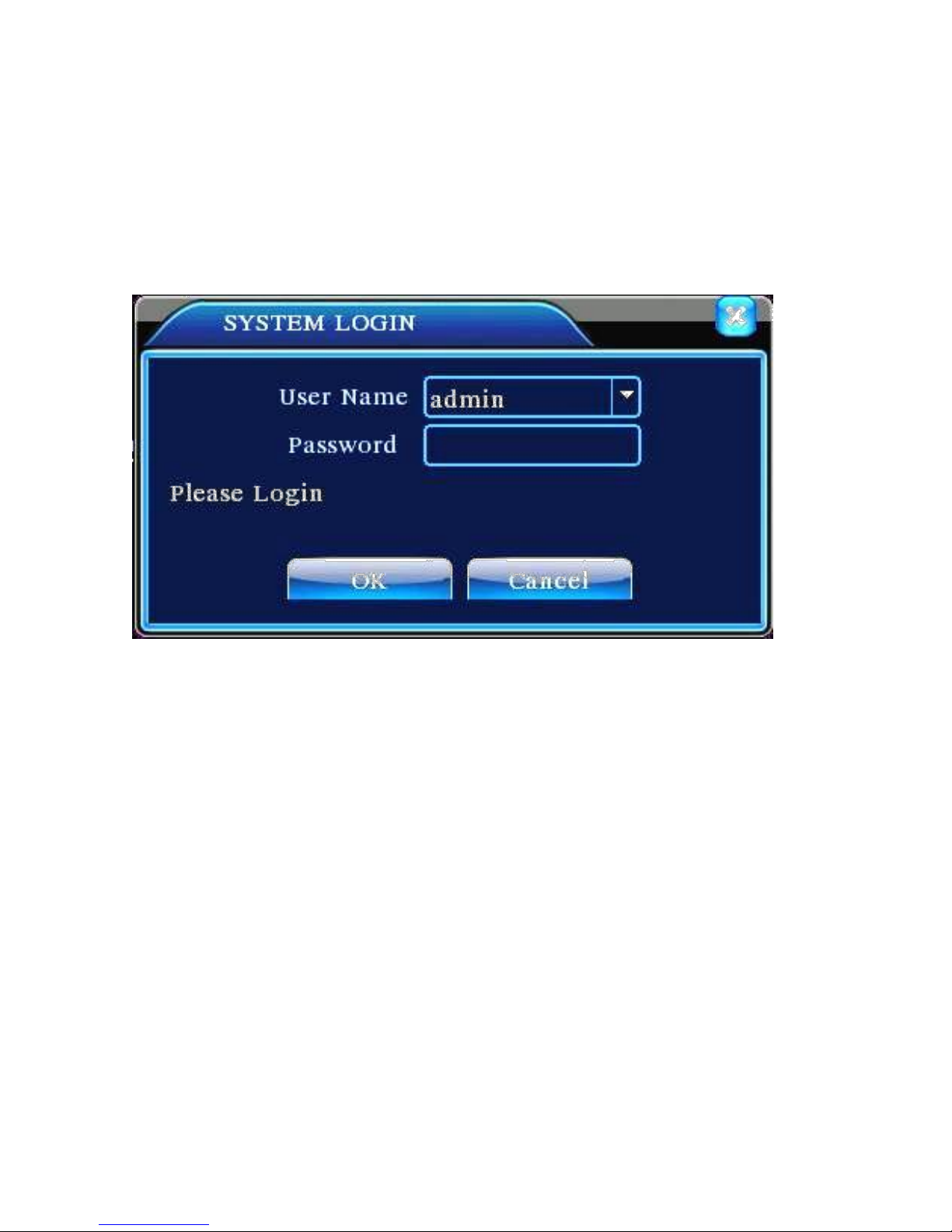
LOGGING INTO THE HVR MENU
Once the HVR is powered up, right-click the mouse and choose
“Main Menu” from the pop-up menu. A window will appear to
prompt you to log in. The default User Name is “admin”. The
password is left blank by default. Click “OK” and you will be
logged in.
NOTE:
If the password has been changed then forgotten or misplaced,
it will be impossible to log into the HVR. In this case please
call SecurityTronix at:
(800) 688-9282 Press “3” for Tech Support, then “2” for Securitytronix Tech
Support.
In order to use the password reset service you must provide
credentials to verify that you are the authorized installer of the
HVR.
4
Page 5
Once logged in, the login screen will close and return to the
main screen. Now, right-clicking the mouse and choosing
“Main Menu” will show the Main Menu screen:
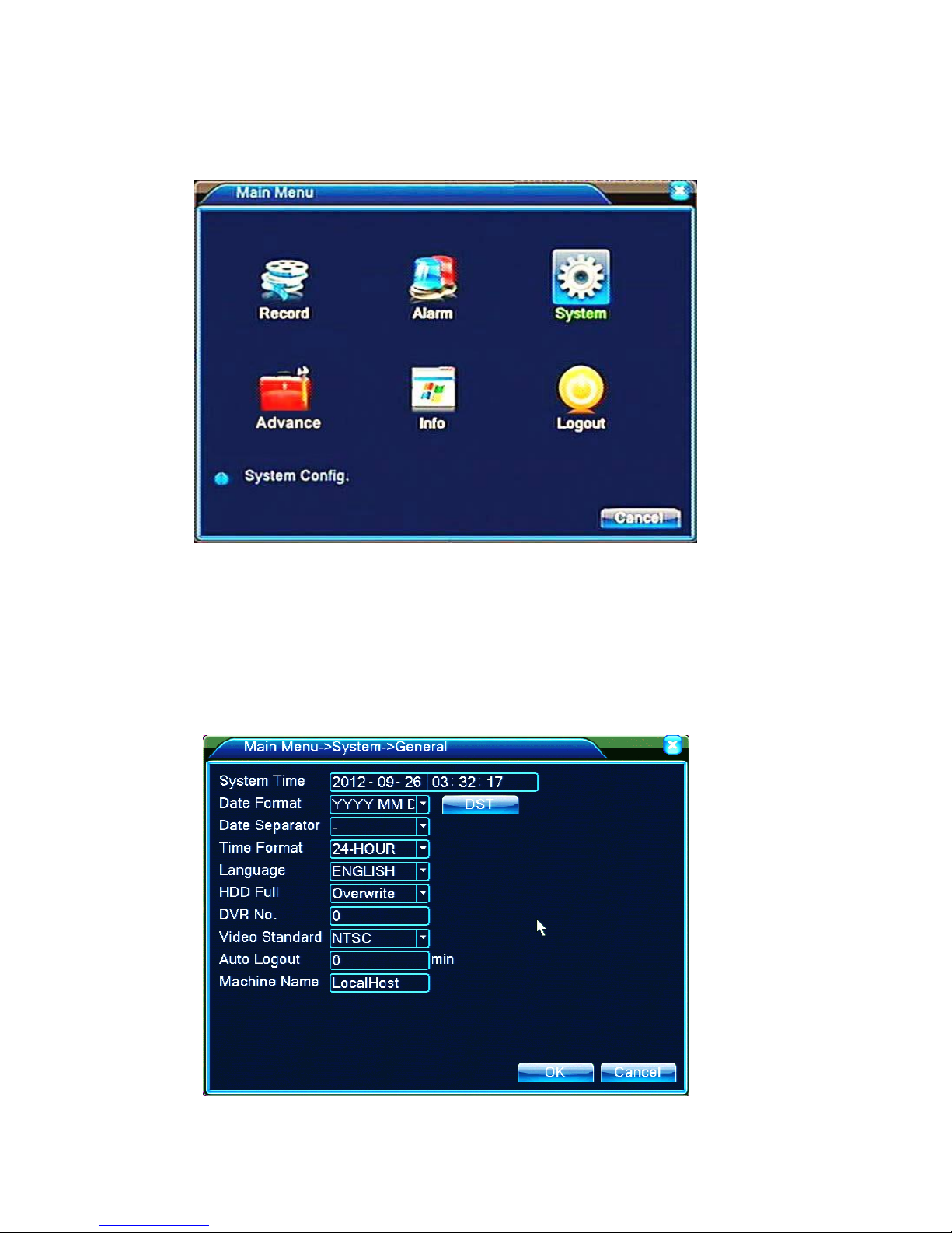
SETTING THE TIME AND DATE
To set the time and date, click the SYSTEM icon on the Main
Menu, then click the GENERAL icon. This will access the
GENERAL screen shown below.
5
Page 6

Next to SYSTEM TIME, click on the year and use the pop-up
number pad to set the current year. Repeat this to set the
current Month and Day. The same process is used to set the
hours, minutes and seconds in the next field, although setting
the time down to the second is not necessary.
If desired, the HVR can be set to automatically adjust the time
for daylight savings time if your locality uses it. Click the DST
button, click the ENABLE checkbox and set which days the
DST becomes active and inactive. Click OK to close the DST
settings box.
Be certain to click OK to lock in the time settings before
exiting the GENERAL SETTINGS menu.
SETTING THE HVR TO RECORD
From the Main Monitoring Screen, RIGHT-CLICK the
mouse and choose RECORD MODE from the pop-up menu.
The RECORD MODE screen will appear:
If it is desired for all 16 channels to record 24hrs / day every
day, click the center button in the left-most row, which
corresponds to ALL channels – MANUAL record. Click OK
to save the setting and all channels will begin recording
immediately. Conversely, to STOP all channels from
recording, click the bottom-left button which corresponds to
6
Page 7

ALL channels – STOP. Clicking OK will then stop all
16 ch HVR shown. Instructions apply to 4ch and 8ch HVRs
channels from recording and prevent them from recording
until further action is taken. If it is desired to use the
schedule for recording, please refer to the full installation
manual which shipped with the HVR. The full manual is
also available at www.securitytronix.com.
MAKING NETWORK CONNECTIONS
To network the HVR for remote viewing, connect a Cat5
network cable from the network port on the rear of the HVR
(#10 below) to any available LAN port on a wired network
switch which has connection to the internet. If the HVR only
needs to be viewed from computers, tablet or phones within
the same LAN, an internet connection is not necessary.
Once the network cable is in place, the HVR must have its
own IP ADDRESS, GATEWAY and SUBNET MASK
settings made to coincide with the existing LAN and router
so the HVR will be recognized on the network.
For the purposes of this Quick Start Guide we will use
DHCP to obtain the network information for the HVR.
Ensure that DHCP is ENABLED on your router, for it to be
able to provide a valid IP address to the HVR. Most
7
Page 8

common residential routers have DHCP enabled by default.
If you are unable to determine this, proceed under the
assumption that it is enabled and the next steps will confirm
if it is enabled or not.
Log in to the MAIN MENU and click the SYSTEM icon,
then the NETWORK icon. The NETWORK menu will be
shown as below:
Click in the checkbox next to DHCP ENABLE so the box
remains checked. Click OK to lock in this setting then restart
the HVR. Once the HVR has rebooted, return to this page.
The settings shown on this network page will be correct. If
the IP address is grayed-out, there may be a problem with
the network cable or connections or the DHCP setting on the
router may not be enabled. If this is the case please check all
cables and connections and consult the router’s user manual
to determine how to enable DHCP.
Forwarding Ports
8
Page 9

Write down the IP ADDRESS from the NETWORK screen
of the HVR. This is the IP address which will be used to
access the HVR “locally” from computers on the same
network (usually in the same building as the HVR). This is
also the address to be used for Port Forwarding.
The process for Port Forwarding will be different for each
router. Consult your router’s manual for specific instructions
regarding the process and follow these guidelines:
3 port numbers must be forwarded: port 80, port 34567
and port 34599.
All 3 port numbers above must be forwarded for both
“TCP” and “UDP” protocols.
All 3 port numbers must be forwarded to the IP address
of the HVR, which was obtained from the NETWORK
page of the HVR in the last step of page 8 of this
guide.
If the HVR is only to be accessed “locally”, it is not
necessary to forward the ports in the router. Port Forwarding
IS necessary to access the HVR from outside of the property
where the HVR is located.
NOTE: The website www.portforward.com has useful resources for
help with forwarding ports on a router.
ACCESSING THE HVR REMOTELY
From the LAN (on premises)
On a computer running Windows XP, Windows 7 or
Windows 8, install the CMS software which is included on
the DVD disk provided with this HVR. Depending on the
computer user’s access rights, the software may need to be
installed and/or run “as administrator”. To do this, right-click
on the software and choose “run as administrator” from the
9
Page 10

pop-up menu.
Once the software opens, the main screen will be presented as
shown below:
Click on the SYSTEM icon near the lower-right corner,
then the DEVICE MANAGER icon near the top-right and
the DEVICE MANAGER window will appear as shown
below:
10
Page 11

There must be at least one ZONE created so the DEVICE
(HVR) can be added to it.
To create a ZONE, click on the ADD AREA icon near the
upper-left corner and the ZONE window will appear as
shown below:
Designate a name for the ZONE and type it into the empty
“Zone” field then click OK to save the information and
create the zone.
Click on the name of the ZONE you just created to
highlight it then click the ADD DEVICE icon . The ADD
DEVICE window will appear as shown below:
11
Page 12

In the DEVICE NAME field enter a name for the HVR to
be added. In the IP ADDRESS field fill in the IP address
obtained from the HVR in the first paragraph on page 9 of
this guide.
The Port can remain at the factory default of “34567” and the
User Name can remain as “admin”. If a password has been
assigned to the HVR enter it in the PASSWORD field . By
default there is no password assigned to the HVR – if a
password has not been set then leave this empty.
Click OK and the DEVICE EDIT screen will close and return
12
Page 13

to the main monitoring screen. The ZONE and DEVICE
(HVR) which were just added will be shown near the upperleft corner of the screen:
DOUBLE-click on the name of the HVR (for this
example, it is named “Test”). The notification area of the
CMS software will display the message “Connect
Successful” and a list of the HVR’s cameras will appear in
the DEVICE column on the left, underneath the name of the
HVR . RIGHT-click on the name of the HVR and
from the pop-up menu choose the option “Connect all video
(Main Stream)”. After a few seconds, the video streams will
show in the preview panes in the center of the CMS software.
13
Page 14

ACCESSING THE HVR REMOTELY
From the WAN (Internet and smart-phone access)
The process for accessing the HVR from a remote location
via the internet is exactly the same as the instructions for ONSITE (LAN) access with one difference; Instead of using the
IP ADDRESS which is set in the HVR itself, the PUBLIC IP
ADDRESS of the property will be used.
One easy way to find the PUBLIC IP ADDRESS of the
property is to use a web browser on a computer connected to
the same router as the HVR and navigate to the website:
www.whatismyip.com
The home page will appear with your IP address as shown
below (outlined in red for clarity).
14
Page 15

Use this IP ADRESS in step (9) on page 12 of this guide.
Ensure that the HVR’s 3 ports are forwarded as described on
page 9 of this guide and follow instructions for accessing the
HVR via the SecurityTronix CMS application described on
pages 9 through 13 of this guide.
For additional support, please contact SecurityTronix Technical
Support:
support@securitytronix.com
(800) 688-9282 Press “3” for Tech Support, then “2” for CCTV Tech
Support.
15
 Loading...