

Page 1
ST-HDoC / ST-HDoC-MM
CVI/TVI/AHD & ANALOG TEST METER
WITH OPTIONAL SDI & DIGITAL MULTIMETER
(Optional Features: ST-HDoC-MM)
User Manual V 1.0
www.nacebrands.com www.securitytronix.com
Page 2

Thank you for purchasing the ST-HDoC Analog and HD camera test monitor!
To use the ST-HDoC safely, please read the Safety Information Carefully.
The manual should be kept with the ST-HDoC for reference.
Keep the serial number label for after-sale service within the warranty period. Please see the last page of the
manual for warranty information.
Batteries come disconnected to ensure they do not drain during shipment. Please connect the battery prior to
powering on the ST-HDoC
If there is any question or problem while using the ST-HDoC HD tester, please contact our SecurityTronix
technical support department at 1-800-688-9282, option 3, and then option 2.
Visit our website http://www.securitytronix.com for additional information.
Page 3

Table of Contents
1.Safety information ............................................................................... Error! Bookmark not defined.
2.Introduction.......................................................................................................................................... 1
2.1 General ................................................................................................................................... 1
2.2 Features .................................................................................................................................. 2
2.3 Function .................................................................................................................................. 3
2.4 Packing List ................................ ............................................................................................ 7
2.5 Front Panel ............................................................................................................................. 8
3.Operation ........................................................................................... Error! Bookmark not defined.3
3.1 Installing the Battery............................................................................................................. 12
3.2 Instrument connection .......................................................................................................... 13
3.3 OSD Menu ............................................................................................................................ 13
3.3.1 PTZ controller ......................................................................................................... 14
3.3.2 Color bar generator .................................................................................................. 17
3.3.3 Video level meter (Optional) * ................................................................................ 18
3.3.4 Video setting ........................................................................................................... 18
3.3.5 PTZ address search .................................................................................................. 19
3.3.6 CVI camera test (Optional) * ................................................................................ 20
3.3.7 TVI camera test (Optional) * ................................................................................. 21
3.3.8 AHD camera test (Optional) * ............................................................................... 21
3.3.9 SDI camera test (Optional) *.....................................................................................25
3.3.10 Cable tracer(Optional)*........................................................................................22
3.3.11 Cable test(Optional)*.............................................................................................22
3.3.12 Digital multimeter (Optional)* ................................................................ ........ 23
3.3.13 Optical power meter(Optional)* ....................................................................... 31
3.3.14 Visual fault locator(Optional)* ......................................................................... 31
3.3.15 TDR tester(Optional)*...................................................................................... 31
3.3.16 Data monitor.......................................................................................................... 31
3.3.17Time setting ............................................................................................................ 31
3.3.18 Device setting ........................................................................................................ 32
3.4 DC12V 1A power output ...................................................................................................... 33
3.5 Audio input test .................................................................................................................... 34
Page 4

3.6 LED lamp ............................................................................................................................. 34
4.Specifications ..................................................................................................................................... 34
4.1 General Specifications .......................................................................................................... 34
4.2 Multimeter specifications ..................................................................................................... 37
Page 5

ST-HDoC / ST-HDoC-MM
1. Safety information
◆ The ST-HDoC/ ST-HDoC-MM is intended for use in compliance with applicable codes and
laws.
◆ Do not expose to moisture.
◆ Do not drop.
◆ The tester should not be charged over 8 hours.
◆ The tester should not be used in an environment with any flammable gas or chemicals.
◆ Do not disassemble the tester except to change the battery.
◆ Don’t use any chemical cleaning products to clean the test meter. Use a dry cloth.
1.1 Digital Multi-meter Safety
◆ Prior to taking any measurements, be sure you are using the correct range, function and input
jack. Red is positive, black is negative.
◆ Never exceed the protection limit value for each range of measurement.
◆ While measuring a live circuit, do not touch any unused terminals.
◆ If the value to be measured is unknown while using the manual range, set the range selector to
the highest position.
◆ Always be careful when working with AC or DC voltages since you could be injured or killed
by voltage going through your body. Keep your fingers behind the probe barriers while
measuring. Do not touch the metal probes while taking any measurements.
◆ Never perform any capacitance measurements unless the capacitor has been fully discharged.
2. Introduction
2.1 General
The 3.5 inch touch screen HD camera monitor and tester, is designed for maintenance and installation
of HD over Coax and analog cameras as well as other security equipment. The 480X320 resolution
enables it to display HD cameras and analog cameras in high resolution. The unit supports many HD
over Coax technologies including HDCVI, TVI, and AHD.
1
Page 6

ST-HDoC / ST-HDoC-MM
The tester is a great compact tool for performing routine maintenance as well as new HD installations.
Test LAN cables for proper connection termination. Other functions include, LED Flashlight, 12VDC
2A power output and much more. Its portability, user-friendly design and many other functions make
the ST-HDoC an essential tool for all installers or technicians.
2.2 Features
Easy to operate 3.5” 480X320 TFT-LCD.
LED Flashlight.
User-defined shortcut keys(F1 and F2)
LCD screen with adjustable brightness/contrast/color saturation.
Automatically adapting NTSC/PAL input.
Enhanced color bar generator, new added gray-scale image test. PAL/NTSC multi-system
color bar video generator (Eight-system switchable, transmit/receive eight-system color
bar).
HD CVI camera image display, coaxial PTZ control and call up the camera OSD menu.
HD TVI camera image display, coaxial PTZ control and call up the camera OSD menu.
AHD camera image display, coaxial PTZ control and call up the camera OSD menu.
TDR cable test, test cable’s open circuit (breakpoint) and short circuit location.
PTZ address scanning for locating PTZ camera Address, Baud and Protocol.
Network cable tester: Tests LAN cable sequence of wires.
Support RS485, Baud Rate adjustable from 600 ~ 115200bps.
Supports more than thirty PTZ protocols, Such as PELCO-P, PELCO-D, SAMSUNG.
PTZ protocol analysis: Control commands are displayed to check RS485 Transmission.
2
Page 7

ST-HDoC / ST-HDoC-MM
PTZ control: Pan, tilt & zoom, focus adjustment, IRIS Open/Close and set preset
positions.
12VDC 1A output power for cameras.
Audio input and output tests. Outputs an audio signal.
Digital multimeter (ST-HDoC-MM)
Lithium Ion Polymer Battery. Remaining battery charge indicator, Lithium Ion Polymer
battery can last up to 11 hours of normal use after charging for 4 -5 hours.
2.3 Function
2.3.1 Video signal test
The new ST-HDoC tester with 3.5 inch LCD-TFT, 480(RGB)x320 resolution, allows the user to view
the images from sufficient angles. The display is suitable for outdoor installation and maintenance
work.
2.3.2 Video level meter (CVBS)
Performs NTSC and PAL video amplitude signal measurements for PEAK to PEAK, SYNC level,
COLOR BURST, and CHROMA level
Video signal PEAK to PEAK level:
For NTSC format, the video signal level is 140±15IRE
For PAL format, the video signal level is 1000±200mV
If the level is too low, it will cause the image to lose quality and limit the distance it will travel over a
coaxial cable. If the level is too high, it will lead to a washed out image.
SYNC level: Testing the amplitude of the video sync pulse to verify if the video level is correct.
For NTSC format, the SYNC level is 40 ± 5IRE
For PAL format, the SYNC level is 300 ± 35mV
If the level is too low, it will cause the image to not frame out properly. If the level is too high, it will
lead to poor video quality.
3
Page 8

ST-HDoC / ST-HDoC-MM
COLOR BURST level: Testing the color burst level will determine if the burst signal is sufficient to
trigger the displays color producing circuit. Burst will diminish in amplitude over longer cable runs and
can fall below the threshold for the video display to show a color image.
For NTSC format, the chroma standard level is 40 IRE
For PAL format, the chroma standard level is 280mV
If the chroma level is too low, the color will not be as deep, and some details of the image will get
washed out. If the chroma level is too high, there may be spots on the image. If the coaxial cable is too
long, it will reduce the chroma level.
2.3.3 PTZ controller
Displays and allows for analysis of analog video and controls pan/tilt/zoom functions of an analog PTZ
camera. For PTZ testing, setup the controlling parameters from the meter to match those of the camera:
e.g. PTZ protocol (PELCO-D, etc.), communication port (RS-485, etc.), baud rate, PTZ camera ID and
pan/tilt speed.
2.3.4 Enhanced Color bar generator
The newly added gray-scale image test, allows the tester to test the monitor for optimal gray-scale
performance. The tester sends out color bars via its BNC output to the monitor. This is used to test for a
problem in the cable going from the camera back to the monitoring area
2.3.5 DC12V 1A output power
The unit can power a camera with 12V DC (1A) power output from the tester. It is helpful for
determining powerline issues or if power supply box is malfunctioning.
2.3.6 Audio testing
Test the audio input from pickup devices. Connect the tester and pickup device with the audio cable.
Consult your local laws and regulations on recording audio and using audio devices. In the
United States of America and all individual states thereof, there are federal and state laws that
limit your ability to monitor and / or record audio. These laws expose you to the risk of criminal
prosecution and potentially give an injured party a civil claim for money damages against you.
2.3.7 Cable tester
Connect a LAN cable from the ST-HDoC/MM unit to the included blue remote cable tester. The unit
will test for connection status, cable type and the status of each wires conductivity will be displayed.
4
Page 9

ST-HDoC / ST-HDoC-MM
2.3.8 PTZ controller
Test the PTZ control command data to diagnose any errors or to ensure there is a sufficient
RS485/RS232 data transmission. The unit receives the control protocol code (PELCO-D, etc.) from a
PTZ keyboard or a DVR with a RS485/RS232 interface.
The unit will display 16 hexadecimal codes such as:
PELCO-P:A0 00(Add) xx xxxxxx AF xx
PELCO-D:FF 01(Add)xx xxxxxxxx
2.3.9 PTZ address scanning
Search the ID/ Protocol/ Baudrate of a PTZ camera being tested.
2.3.10 CVI camera test
This displays an HD CVI camera image. It supports 720p @ 25/30/50/60fps & 1080p @ 25/30fps. The
features are live video and coaxial PTZ control including calling up the camera’s OSD menu.
2.3.11 TVI camera test
This displays an HD TVI camera image. It supports 720p @ 25/30/50/60fps & 1080p @ 25/30fps. The
features are live video and coaxial PTZ control including calling up the camera’s OSD menu.
2.3.12 AHD camera test
This displays an HD TVI camera image. It supports 720p @ 25/30fps & 1080p @ 25/30fps. The
features are live video and coaxial PTZ control including calling up the camera’s OSD menu.
2.3.13 SDI camera test (ST-HDoC-MM only)
This displays an HD SDI camera image. It supports 720p @ 25/30fps & 1080p @ 25/30fps. The
features are live video and coaxial PTZ control including calling up the camera’s OSD menu.
5
Page 10

ST-HDoC / ST-HDoC-MM
2.3.14 Cable tracer
Cable Tracing is not available with the ST-HDoC series testers.
2.3.15 Digital multimeter (ST-HDoC-MM only)
The ST-HDOC-MM has a highly accurate 33/4 digit (6600) built in digital multi-meter. It is used to
measure AC and DC voltages, current, resistance, continuity, capacitance and diode testing. It can
switch between auto and manual measuring ranges.
2.3.16 Optical Power Meter
Optical power testing is not available with the ST-HDoC series testers.
2.3.17 TDR open circuit
TDR testing is not available with the ST-HDoC series testers.
2.3.18 Visual fault locator
Visual Fault Locator is not available with the ST-HDoC series testers.
2.3.19 LED lamp
Press the LED On/Off button to use the LED flashlight.
2.3.20 F1, F2 User-defined shortcut keys
The user-defined shortcut key is designed for improving operator efficiency. Once configured, the F
keys can be used to quickly call up functions that are most commonly used.
6
Page 11

ST-HDoC / ST-HDoC-MM
2.4 Packing List
1) ST-HDoC video monitor
2) 5VDC 1.5A power adapter(with USB cable)
3) No.255 cable tester
4) Lithium Ion Polymer Battery(3.7V DC 3000mAh )(typically not plugged in)
5) 3 foot BNC test cable
6) 18 inch RS485 test cable with alligator clips
7) Multi meter test leads (red and black) (only for the ST-HDoC-MM model)
8) 3 foot camera powering cable
9) 18 inch 3.5mm audio microphone or speaker cable with alligator clips
10) Carrying case and hanging strap with front accessory pouch
11) User’s manual
7
Page 12
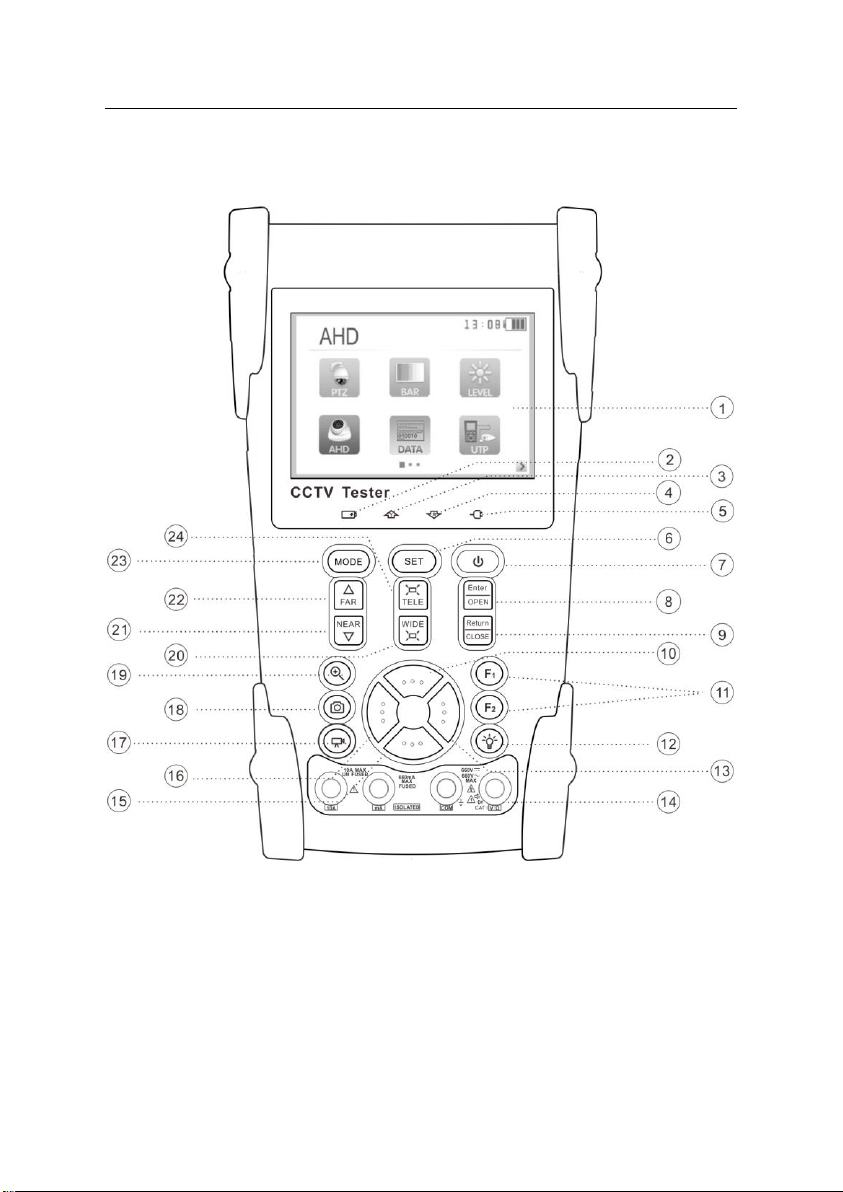
2.5 Front Panel
ST-HDoC / ST-HDoC-MM
8
Page 13
ST-HDoC / ST-HDoC-MM
1 OSD menu
2
The charge indicator: it glows red while the battery is being charged. As the
charging is complete, the indicator turns off automatically
3 The data-transmission indicator: it glows red while data is being transmitted
4 The data-reception indicator: it glows red while data is being received
5 The power indicator: it glows green while the tester is powered on
6 Set key, press to enter sub-menu
7
Press for more than 2 seconds to turn off the device ,quick press to turn on or off the
menu display
8 Confirm/Open : Confirm the setting of a parameter; open or enlarge the aperture
9
Return/Close : Return or cancel while setting parameters, close or decrease the
aperture
10
Upward: Select the item which will be set or add the value of the parameter. Tilt the
PTZ upward
11 User-defined key(can be customized for quick access functions)
12 LED Lamp
13
Rightward, Enter the sub-menu or select the parameter whose value will be changed.
Add the value of the parameter. Pan the PTZ right
14
Digital multimeter: voltage, current, resistance and capacitance measuring,
continuity testing, diode testing (ST-HDoC-MM only)
15
Downward: Select the item which will be set or reduce the value of the parameter.
Tilt the PTZ downward
16
Leftward: Enter the sub-menu or select the parameter whose value will be changed.
Reduce the value of the parameter. Pan the PTZ left
17 Color bar generator shortcut key
18 PTZ control shortcut key
19
AHD,CVI or TVI shortcut key (Customizable) *
9
Page 14
ST-HDoC / ST-HDoC-MM
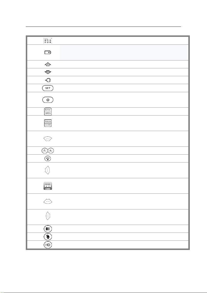
20 WIDE: zoom out the image
21 Near focus: Focus the image near
22 Far focus: Focus the image far
23 Menu key
24 TELE: zoom in the image
10
Page 15

ST-HDoC / ST-HDoC-MM
25
Analog / HD TVI/CVI/AHD signal input (BNC interface)
26
Video output (BNC output interface): CVBS output
27
Optical power meter interface (Optional) */ Visual fault locator interface (Optional) *
28
TDR cable open circuit and short circuit test (Optional) *
29
12V DC 1A output
30
SDI test port (BNC interface) ( Optional) *
31
LED lamp
32
RS485Interface: RS485 communication for PTZ
33
Network cable /Telephone cable test port
34
Device charging port (Mini USB)
35
No function
36
No function
37
Audio input: for testing audio pickup equipment
38
Reset the device to factory original settings
11
Page 16

ST-HDoC / ST-HDoC-MM
3. Operation
3.1 Installing the Battery
The tester has a built-in lithium ion polymer rechargeable battery. Prior to the use of the unit, the
battery cable connection behind the battery door needs to be connected and the unit fully
charged for no more than 8 hours prior to use.
Pressing key for 2 seconds can power on or off the tester.
Notice:Please use the original power adapter for the device!
At the first time of use, the batteries should be completely exhausted and then recharged for 4 or
5 hours.
The Charge Indicator lights red when charging the battery, and turns off automatically
when charging is complete.
Notice: When the Charge Indicator turns off, the battery is approximately 90%
charged. Do not charge for more than one hour after the indicator has turned off.
Press the RESET key at the left of the meter to restore the default settings if the tester
works abnormally.
Multi meter: the red and black multi meter pins must be inserted in the correct port.
12
Page 17

ST-HDoC / ST-HDoC-MM
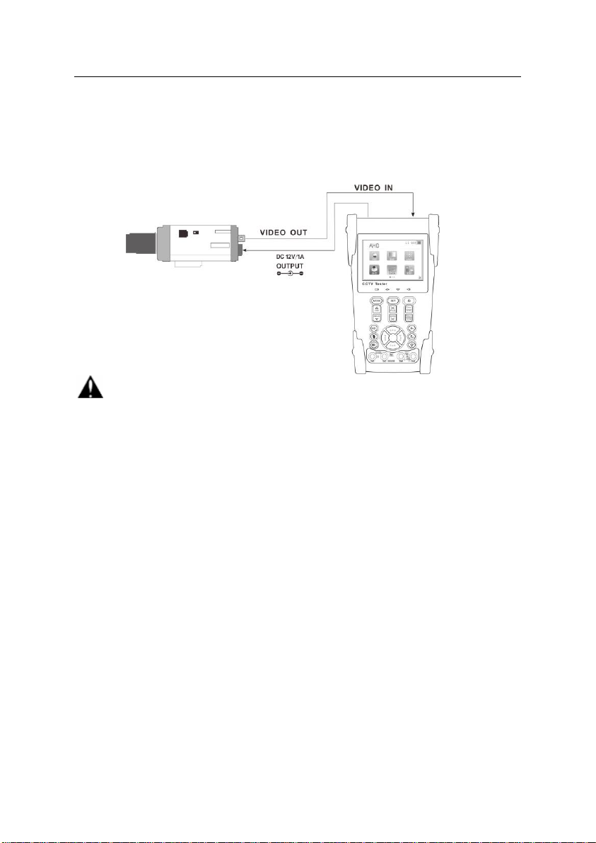
3.2 Instrument connection
⑴. The camera or speed dome to be tested should be connected to the “VIDEO IN” port.
⑵. The ST-HDoC “VIDEO OUT” interface is for connecting to an auxiliary BNC monitor.
⑶. Connect the camera or the speed dome’s RS485 controller cable to the tester’s RS485 interface
(Note positive and negative connection of the cable).
3.3 OSD Menu
Press the key to turn the tester on.
Press the key again to turn off, you can also set
the meter to automatically power off.
Enter the menu ,choose one function to enter , then short
press the key,
While in the main menu, pressing quickly switches to the different menu lists.
While in the main menu, continuously press the key to select different function. Once a
selection is made, press the key to enter.
13
Page 18

ST-HDoC / ST-HDoC-MM
Press the key to switch between menu pages, the square icon at the bottom
of the screen indicates the different pages of apps available.
Press the key to select the different function icon, then press the key to enter
First page menu Second page menu
3.3.1 PTZ controller
Connect an analog PTZ camera to the tester, and open the PTZ controller app. From this menu, you
can view the video stream as well as control PTZ movements. From within the PTZ app, you can also
configure parameters such as: Protocol, Baud Rate, Address,
Pan/Tilt speed, Preset call and recall.
PTZ controller parameter settings
In the “PTZ CONTROLLER ” app(as shown in above photo), press the key to enter the
parameter settings .
Press the key , to move the yellow cursor to select a parameter.
Press the key or , to change the parameter values. Then press the key to save and
return.
14
Page 19

ST-HDoC / ST-HDoC-MM
A. Protocol
Use the up and down arrow keys to move the yellow cursor to
the “protocol ” function, from here, you can set the
corresponding Protocol. The tester supports more than 30
different protocols, including Pelco, Samsung, Bosch, etc.
B. Port
The default port for the ST-HDoC is set to RS485 for analog PTZ cameras, with UTC protocols being
embedded in the corresponding HDoC app.
C. Baud
Move the yellow cursor to “Baud” function, select the baud rate according to baud rate of the PTZ
camera.(600/1200/2400/4800/9600/19200/57600/115200bps)
D. Address
Set the ID according the ID of PTZ camera (0~254), the address settings must be consistent with that of
the PTZ camera being tested.
E. Pan speed: Set the pan speed of the PTZ camera (0~63)
F. Tilt speed: Set the tilt speed of PTZ the camera (0~63)
G. Set preset position (Set PS)
Move the yellow cursor to “SET PS”, to save the preset position number (1~128), Press the key
To accelerate the value change, then press the key to save.
H. Call the preset position (Go PS)
Move the yellow cursor to “Set PS”, then enter the desired preset position (1~128),
Press the key or to accelerate the value changing.
Press the key to complete preset position settings.
*Some PTZ cameras require special preset numbers to call specific menus/ functions.
Check and set the protocol, address, interface and baud rate, that they are the same as the dome camera,
then you can test and control the PTZ camera.
15
Page 20

ST-HDoC / ST-HDoC-MM
Press the key to control the PTZ direction of rotation
Press the key or to switch on or turn off the aperture.
Press the key or , adjust the focus manually
Press the key or , manually adjust the zoom
1) Set and go PS
Set PS:
A. Use the PTZ controls to move the camera to the desired position.
B. Press the key to enter the PTZ controller submenu. Press the key to move the
yellow cursor to “Set PS”, Press the key to select the desired preset position number.
Then Press the key to save the preset position.
Go PS:
Call the preset position. (1~128) The PTZ camera will go to the desired preset position.
In “PTZ Controller”, Press the key to enter the PTZ controller submenu. Press the
key, to move the yellow cursor to “GO PS”. Press the key to select the desired preset number.
Then press the key to call the preset position.
The camera moves to the preset position immediately, Lens zoom, focus and iris is will automatically
change to the preset parameters provided the camera is equipped with these features.
Tips:Preset position setting is saved in the PTZ camera’s built in memory.
2) Menu of dome
The PTZ camera manufacturers may have different procedures for accessing the PTZ camera menu.
Please refer to the camera manual for specific instructions to access the PTZ menu. For example if the
camera menu is accessed by CALLING PRESET 64, use the steps below.
a. Press the key to enter PTZ controller submenu
b. Press the key , select preset position 64
c. Press the key to enter the main menu of the PTZ camera’s OSD.
16
Page 21

ST-HDoC / ST-HDoC-MM
OSD Menu of Dome (For
Reference only)
After calling the PTZ camera menu, Users can select different functions using the arrow keys. Please
refer to the PTZ camera’s manual for help with navigating/ configuring the PTZ OSD menu.
3.3.2 Color bar generator
Press the key to enter the tester’s main menu
Press the key to select the and then press the key to enter
The tester’s color bar generator supports both PAL and NTSC format color bars.
Press the key or , to move the cursor to “Format”、“LCD”、or “Type ”. Format can be
switched between NTSC or PAL. LCD video output can be changed from Video output mode ( Color
bar out to a test monitor), or Input mode to test analog (CVBS) incoming signals through the BNC port.
Short press the to turn off the menu, and full screen the color bar output;short press it again to
display the color bar generator menu.
In the “ color bar generator” mode, both PAL / NTSC format’s color bar can output by the tester’s
17
Page 22

ST-HDoC / ST-HDoC-MM
“Video OUT ” port, and received by the tester’s “Video IN ” port.
This feature is used for testing the video transmission system, such as optical video transmitter and
receiver, video cables, etc. The tester’s “Video OUT ” port connects to the sending port of the optical
video transmitter , the “Video IN ” port connects to the receiving port of the optical video transmitter .
Application:
A. When servicing a camera, send the image to the monitoring center, if the monitoring center can
receive the image, it means that the Video transmission channel is normal, in addition, the monitor
center can judge the image quality through the received color bar.
B You can send one of several different color pallets to determine if the display monitor is calibrated
properly.
C .Send gray scale test bar, to debug a monitor’s grayscale performance.
3.3.3 Video level meter
The ST-HDoC/ ST-HDoC-MM is not equipped with the Video level meter.
3.3.4 Video setting
Press to access the menu, press to enter.
LCD brightness, contrast, color saturation can be adjusted.
The ST-HDoC auto displays the format (PAL/NTSC) of the video input, and analyzes the input
video signal level.
If the coaxial cable is too long, it will reduce the video signal level. If the level is too low, the image
will not be as deep and its dynamic range will be reduced. If the level is too high, the image will
get washed out. There will be prompts that appear on screen if the level out of range.
18
Page 23

ST-HDoC / ST-HDoC-MM
Depending on the type of camera connected to the ST-HDoC, the Video “Format ” will automatically
switch between NTSC and PAL, and the Video Level will automatically switch between IRE (Institute
of Radio Engineers) and mV. NTSC signals measured in IRE units, PAL signals are measured in mV.
3.3.5 PTZ address search
Press to select then press to enter.
Note:Please isolate the PTZ camera from other PTZ cameras before searching. Otherwise all
the PTZ cameras in the same system will be programmed at the same time.
Press to select , and then press to enter device settings. Select “Address search”,
press to select ON or OFF, then Press to save. The PTZ address search function
will now display on the main menu.
(Note:When the ST-HDoC is turned off, the Address search is defaulted to OFF)
Press the key to set: protocol and baud rate (be sure to match the PTZ camera settings)
Press the button, and the tester will search for the ID quickly and continuously. When the ID is
found, the PTZ camera will pan right. At this time, please press to stop searching.
19
Page 24

ST-HDoC / ST-HDoC-MM
Press the key with single clicks, to search for PTZ ID one address at a time. When the ID is
discovered, the PTZ camera will stop panning.
Manual address search: Press or to search the address gradually, the image will flash
when the address is found. Press the direction control button to adjust the Speed Dome
Camera. Press the button to quit.
3.3.6 CVI camera test
Connect a CVI camera to the ST-HDoC’s “AHD, CVI, TVI” interface.
Press the key to enter the tester’s main menu, then press the keys to select CVI. Press
the key to enter CVI test.
PTZ control (over coaxial cable, if the camera is equipped):
Press key to open the menu, then press key to switch the control between coaxial
control (UTC) and RS485 control.
PTZ control instructions, please refer to “3.3.1 PTZ control”
20
Page 25

ST-HDoC / ST-HDoC-MM
3.3.7 TVI camera test
Connect a TVI camera to the ST-HDoC’s “AHD / TVI / CVI ” interface.
Press key to enter the tester’s main menu, then press key to select “TVI” ,
press the key to enter TVI test.
For PTZ control and camera OSD menu operation instructions, please refer to 3.3.6 CVI camera test.
3.3.8 AHD camera test
Connect an AHD camera to the ST-HDoC’s “AHD / TVI / CVI” interface.
Press key to enter the tester’s main menu, then press key to select “AHD” ,
Press key to enter AHD test.
For PTZ control and camera OSD menu operation instructions, please refer to 3.3.6 CVI camera test.
21
Page 26

ST-HDoC / ST-HDoC-MM
3.3.9 SDI camera test (ST-HDoC-MM)
Connect an SDI camera to the ST-HDoC’s “SDI” interface.
Press the key to enter the tester’s main menu, then press the key to select
“SDI” , Press key to enter SDI test.
PTZ control instructions, please refer to 3.3.1 PTZ controller
3.3.10 Cable Tracer
The ST-HDoC/ ST-HDoC-MM is not equipped with the Cable Tester Function.
3.3.11 Cable tester
Press the key to enter the tester’s main menu, then press the key to select
then press to enter.
Testing a LAN or telephone cable.
Connect a LAN or telephone cable to the ST-HDoC tester, and the other end into the cable tester
marked ( No.255) . Once connected, the cable type and sequence of wires will be displayed, including
the model number of the Cable tester kit.
22
Page 27

ST-HDoC / ST-HDoC-MM
Note: The number of the cable tester is 255.
3.3.12 Digital Multi-Meter(ST-HDoC-MM ONLY)
Press the key to enter the tester’s main menu, then press the key to select
then press to enter.
1) Function Button:
:Auto range :Data hold :Relative measuring
:Function select :Manual range
2) SYMBOLS:
U:DC Voltage Measuring U~:AC Voltage Measuring
A:DC Current Measuring A~:AC Current Measuring
Ω:Resistance Measuring :Continuity Testing
:Diode Testing :Capacitance Measuring
23
Page 28

ST-HDoC / ST-HDoC-MM
AC/DC
Voltage and current measurement display
Auto- range
Automatically adjust the display range based off the device tested
Data hold
When pressed, the current measurement display will hold for reference
Relative
measurement
Display the relative measurement value, press the key again to change the
display state
10A socket
For use when measuring current up to 10Amps
Over range
The current measurement is over the rated value, switch to auto-range to
obtain the proper measurement.
WARNING!
Input voltage not to exceed 660V DC!
Use extreme caution when measuring high voltage.
3) OPERATING INSTRUCTION
A. DC Voltage Measuring
a. Connect the black test lead to the “COM ” jack and the red test lead to
the “V/Ω” jack.
b. Press to select U, to enter the DC voltage measurement.
c.Auto range by pressing the key, and manual range by press pressing the keys
d.Manual range: 0.000V 6.600V range
00.00V 66.00V range
000.0V 660.0V range
000.0mV 660.0mV range
24
Page 29

ST-HDoC / ST-HDoC-MM
WARNING!
You can’t input the voltage which more than 660V AC, it’s possible to show higher voltage, but it
may destroy the inner circuit.
Pay attention not to get an electric shock when measuring high voltage.
CAUTION!
Shut down the power of the tested circuit before making connections to the digital multi-meter!
WARNING!
Input voltage not to exceed 660V DC!
Use extreme caution when measuring high voltage.
B. AC Voltage Measuring
a. Connect the black test lead to the “COM” jack and the red test lead to the “V/Ω” jack.
b. Press and select U ~ , to enter the AC voltage measurement. Auto range by pressing the
key, and manual range by pressing the keys
Manual range: 0.000V 6.600V range
00.00V 66.00V range
000.0V 660.0V range
000.0mV 660.0mV range
C. DC Current Measuring (Manual Range ONLY!)
a. Connect the black test lead to the “COM ” jack and the red test lead
to the “mA” jack for a maximum of 660mA current. For a maximum
of 10A, move the red lead to the 10A jack.
b. Press to select A, to enter the DC current measurement.
Manually adjust the range by pressing the buttons.
Manual range: 0.000mA 6.6mA range
00.00mA 66.00mA range
000.0mA 660.0mA range
25
Page 30

ST-HDoC / ST-HDoC-MM
WARNING!
Shut down the power of the tested circuit before making connections to the digital multi-meter!
00.00A 10.00A range(use 10A unfused socket)
c. Connect the test leads in series with the load under measurement.
d. Once power is applied to the circuit, the current load reading will display on screen.
NOTE:
When the figure “OL” is displayed, it indicates an over range situation, and the higher range has to
be selected.
When the value scale to be measured is unknown beforehand, set the range selector at the highest
position.
The maximum current of mA socket is 660mA, over-current will destroy the fuse, and will damage
the meter.
The maximum current of 10A socket is 10A, over-current will destroy the meter, and potentially
cause bodily-harm.
D. AC Current Measuring (Only Manual range)
a. Connect the black test lead to the “COM” jack and the red test lead to
the“mA” jack for a maximum of 660mA current. For a maximum of
10A, move the red lead to the 10A jack.
b. Press to select A~ , to enter the AC current measurement.
Manually select the range by pressing the buttons.
Manual range: 0.000mA 6.600mA range
00.00mA 66.00mA range
000.0mA 660.0mA range
26
Page 31

ST-HDoC / ST-HDoC-MM
WARNING!
When measuring in-circuit resistance, be sure the circuit under test has all power removed and that all
capacitors have been fully discharged.
00.00A 10.00A range(use 10A socket)
c. Connect test leads in series with the load under measurement.
d. Once power is applied to the circuit, the current load reading will display on screen.
NOTE:
When only the figure “OL” is displayed, it indicates over range situation and the higher range has to
be selected.
When the value scale to be measured is unknown beforehand, set the range selector at the highest
position.
The maximum current of mA socket is 660mA; over-current will destroy the fuse, and will damage
the meter.
The maximum current of 10A socket is 10A, over-current will destroy the meter, and potentially
cause bodily harm.
Applying DC voltage while in “AC” mode, will damage the test meter.
E. Resistance Measuring
a. Connect the black test lead to the “COM ” jack and the red test lead to the“V/Ω” jack.
b. Press to select Ω, to enter the Ω measurement. Auto range by pressing the key, and
manual range by pressing the buttons. .
Manual range:(Connect the red lead to the black lead, to display the measurement range)
000.0Ω 660Ω range
0.000 KΩ 6.600KΩ range
00.00 KΩ 66.00KΩ range
000.0 KΩ 660.0KΩ range
0.000 MΩ 6.600MΩ range
27
Page 32

ST-HDoC / ST-HDoC-MM
WARNING!
When testing the circuit continuity, be sure that the power of the circuit has been shut down and all
capacitors have been fully discharged.
00.00 MΩ 66.00MΩ range
c. Connect the test leads to the device being measured.
d. Once connected the resistance will be displayed on screen.
NOTE:
When only the figure “OL” is displayed, it indicates over range situation and the higher range has to be
selected.
F. Continuity Testing
a. Connect the black test lead to the “COM” jack and the red test lead to the “V/Ω” jack.
b. Press to select , to enter the continuity test.
c. Connect test leads across two point of the circuit being tested.
d. If continuity exists (i.e., resistance less than about 50Ω), the
built-in buzzer will generate an audible tone.
e. You can also get reading from the LCD indicating continuity.
G. Diode Testing
a. Connect the black test lead to the “COM” jack and the red test lead to the “V/Ω” jack.
b. Press to select , to enter the diode test.
c. Connect test red lead to the anode of the diode under test.
d. Connect the black lead to the cathode of the diode under test.
E .If the tested Diode has forward voltage of 3V or more, an audible tone will sound, indicating proper
diode operation.
F.The capacitance of a capacitor should be tested separately.
28
Page 33

ST-HDoC / ST-HDoC-MM
WARNING!
To avoid electric shock, be sure the capacitors have been fully discharged before measuring the
capacitance of a capacitor.
H. Capacitance Measuring
a. Connect the black test lead to the“ COM ” jack and the red test lead to the “V/Ω ” jack.
b. Press to select ,to enter the capacitance measurement.
Auto range by pressing ,and manual range by pressing .
Manual range:0.000nF 6.600nF range
00.00nF 66.00nF range
000.0nF 660.0nF range
0.000uF 6.600μF range
00.00uF 66.00μF range
000.0uF 660.0μF range
0.000mF 6.600mF range
00.00mF 66.00mF range
c. Before connecting the test leads across the two sides of the capacitor under measurement, be sure that
the capacitor has been fully discharged.
d. The capacitance will be displayed on the LCD.
Note:
a. The capacitance of a capacitor should be tested separately, do not test a capacitor while it is
connected to a circuit.
b. To avoid electric shock, be sure the capacitors have been fully
discharged before measuring the capacitance of a capacitor.
c. While testing the capacitance of a capacitor up to 660uF, the Maximum
testing time is 6.6 seconds. If the capacitor is leaking or otherwise damaged, no data will be
displayed. The tester will resume normal operation after disconnecting the capacitor.
29
Page 34

ST-HDoC / ST-HDoC-MM
Manual range and Auto range
Press the key to change the value, press the
Key for auto measurement
Data hold
Press the key to hold the data, the color will change to
Green, when the data is held. Press it again to quit and resume
normal operation.
Relative value measurement
Press the key to enter relative value measurement.
The tester will display the relative value in red. Press it
again to quit and resume normal use.
The hold function and the relative value can be combined,
the display value will be yellow.
Voltage protection
Input voltage not to exceed 660V AC/DC, applying
overvoltage to the tester will damage it, and may cause
bodily harm.
Resistance、Continuity、Diode、PTC component Protection
Incorrect input voltage will trigger the protection mode which is only suitable for a short time.
If the input voltage is over 600V, it will damage the tester and may cause bodily harm.
mA current fuse range :250V 1A
When using the 660mA fused socket, if over 250v is applied, the glass fuse will melt to protect the
meter. Please be sure to change the fuse with an identical type (fuse located behind battery).
Note: 10A socket does NOT have fuse protection, if over current is applied it will damage the
tester, and may cause bodily harm.
30
Page 35

ST-HDoC / ST-HDoC-MM
3.3.13 Optical Power Meter
The optical power meter feature is not available with the ST-HDoC
3.3.14 Visual Fault Locator
The visual fault locator is not available with the ST-HDoC
3.3.15 TDR Tester
The TDR tester is not available with the ST-HDoC
3.3.16 Data monitor
Press to select , then press to enter.
Press to choose the baud rate of the RS485 interface; baud rate must match the device
being monitored ( DVR/ PTZ controller/ etc.)
The DVR or Control keyboard sends the code to the tester, if it can be read, the protocol will display on
the upper right.
Press to clear the display while the tester is receiving command information.
3.3.17 Time setting
Press to enter the menu, then press to enter.
Note:Press to set the parameter of the time, press to save.
31
Page 36
ST-HDoC / ST-HDoC-MM
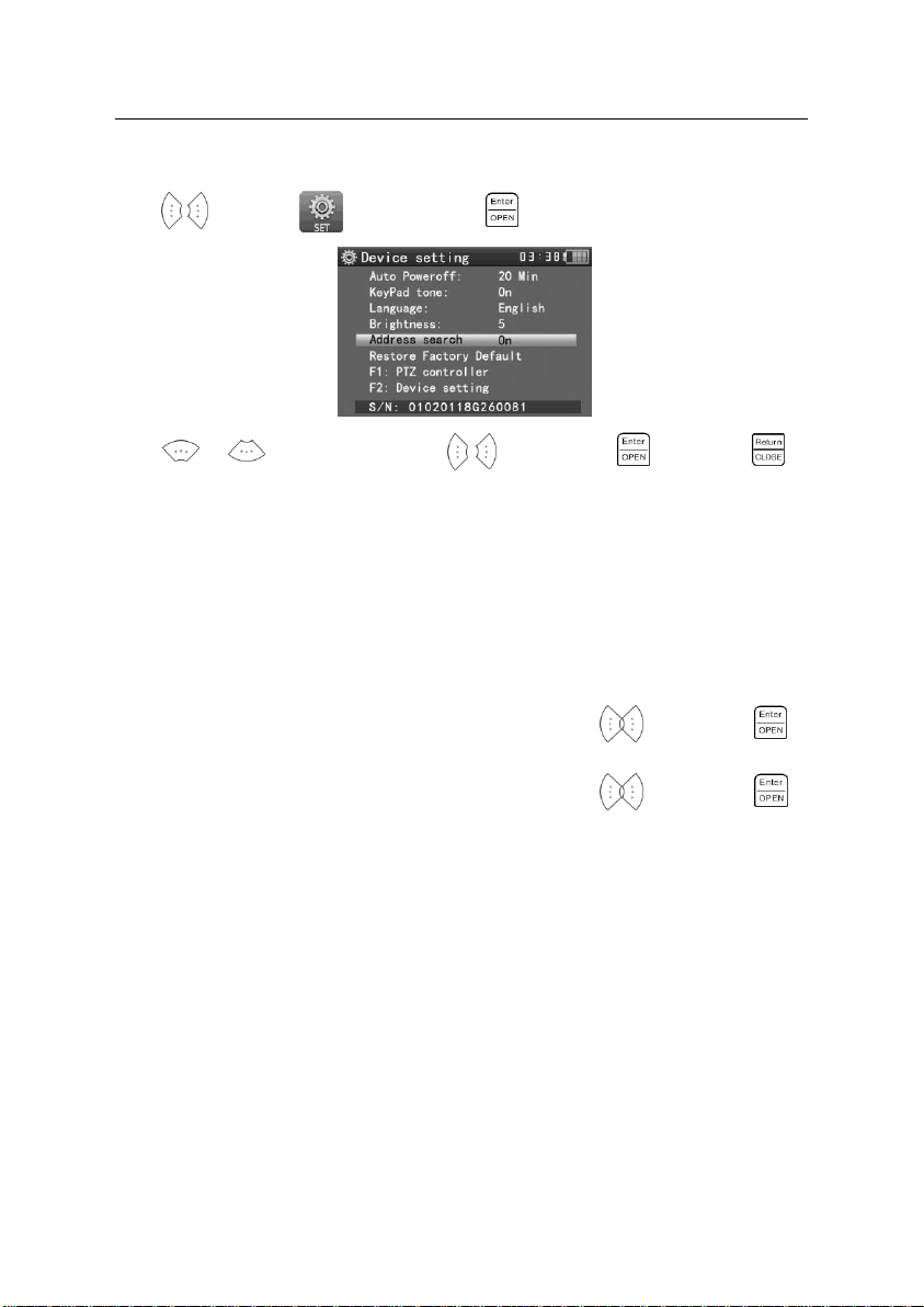
3.3.18 Device setting
Press to enter the menu, the press the key to enter.
Press or to choose the item, press to adjust, press to save, press
to quit.
Auto power off: You can set the meter to auto power off in 5, 10, or 60 minute intervals.
Keypad tone: You can enable or disable the audible beep when pressing keys.
Language: Select your desired language: English, Chinese, etc.
Brightness: Set the brightness of OSD menu and background. (0~7)
PTZ address search: Select off / on to add or remove the PTZ address search function.
Restore default data: Restore the device to factory defaults.
F1 user-defined shortcut key : You can set the function as you like, press to select, press
to save. The default F1 key is the “ PTZ controller”.
F2 user-defined shortcut key : You can set the function as you like, press to select, press
to save. The default is F2 key is the “Device setting”.
32
Page 37
ST-HDoC / ST-HDoC-MM
3.4 DC12V 1A power output
Power a compatible camera with the 12V DC (1A) power output from the tester. The DC power output
can be useful when troubleshooting power line issues.
Notice
a. Do not apply input power to the power output port of the ST-HDoC as this can damage the tester.
b. Do not apply the output power of the ST-HDoC to the input port as this can damage the tester.
c. If a camera that draws more than 1A of power is connected to the output port of the ST-HDoC, it
will enter self-protection mode. Under this condition, disconnect the output power of the meter to
the camera, and use an external compatible power supply to power the camera.
d. For extended use of the power out feature of the ST-HDoC, please be sure that the battery has at
least a 50% charge.
33
Page 38

ST-HDoC / ST-HDoC-MM
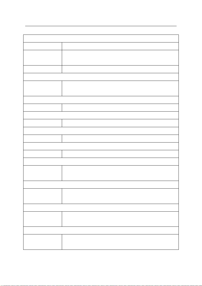
Model
ST-HDoC / ST-HDoC-MM
Video Test
Signal mode
NTSC/PAL (Auto adaptive)
Display
3.5 inch HVGA TFT-LCD, 480(RGB)x 320 resolution
LCD adjustment
Brightness, Contrast, Saturation adjustable
Video IN/OUT
1 channel BNC Input & 1 channel BNC Output
Video Output Mode
1.0 Vp-p
Video Signal Test
Video signal test
Video signals measured in IRE or mV
3.5 Audio input test
Test the audio input from pickup devices. Connect the tester and audio source using the supplied cable.
NOTE: Please check your local laws governing the use of audio recording/monitoring equipment.
3.6 LED lamp
The ST-HDoC is equipped with an on board LED flashlight located on the top of the unit.
Turn on the tester, press for several seconds, and the LED lamp will turn on, press again
to turn off the lamp.
4、Specifications
4.1 General Specifications
34
Page 39
ST-HDoC / ST-HDoC-MM
PTZ Controller
Communication
RS485 / UTC
PTZ Protocol
Compatible with more than 30 protocols such as PELCO-D/P, Samsung,
Panasonic, Lilin, Yaan, etc.
Baud Rate
600,1200, 2400, 4800, 9600, 19200, 57600, 115200bps
Video Signal Generation
Color bar generator
Supports both PAL / NTSC format’s standard color bar output (Red, Green,
Blue, White, Black, Grey)
UTP Cable Tester
UTP cable test
Displays UTP cable connection status , cable type and sequence of wires
12V DC (1A) Power Output
12VDC power output
12V DC (1A) Output for powering cameras
Audio Input Test
Audio input test
1 channel audio signal input, support audio recording
RS485 data analysis
Data Monitor
Captures and analyzes the command data from a controlling device
CVI Test
CVI video signal test
1 channel CVI input(BNC interface), supports 720p 25 / 30 / 50 / 60fps,
1080p 25 / 30fps, coxial PTZ controller, UTC control
TVI Test
TVI video signal test
1 channel TVI input(BNC interface), supports 720p 25 / 30 / 50 / 60fps,
1080p 25 / 30fps, coxial PTZ controller, UTC control
AHD Test
AHD video signal test
1 channel AHD input (BNC interface), supports AHD 2.0, 720p 25 / 30fps,
1080p 25 / 30fps, coxial PTZ controller, UTC control
SDI Test(ST-HDoC-MM)
SDI video signal test
1 channel SDI input (BNC interface), support 720p 50 / 60fps, 1080p 50 /
60fps, PTZ controller
35
Page 40

ST-HDoC / ST-HDoC-MM
Digital Multimeter ( ST-HDoC-MM)
AC/DC Voltage
0-660V auto/manual range, minimum resolution of 0.1mV
AC/DC current
660.0uA , 6.600mA, 66.00mA , 660.0mA, 10.00A
Resistance
660.0Ω, 6.600kΩ, 66.00kΩ, 660.0kΩ, 6.600MΩ, 66.00MΩ
Capacitance
6.6nf~66000uF, minimum resolution of 1pf
Diode
0~2V forward voltage, minimum resolution of 1mV
Data hold
Hold and display the measured value
Relative measurement
Display the relative power value
Continuity testing
Built-in buzzer will sound, if resistance is lower than 50 Ω
Testing speed
3 samples per second
Data range
-6600~+6600
POWER
Power Adapter
5V DC(1.5A)Mini USB interface
Battery
Built-in 3.7V Lithium polymer battery ,3000mAh
Rechargeable
After charging 3-4 hour, 11 hour average work time
Low Consumption
Energy saving , battery capacity indicator
Parameter
Operation setting
OSD menu, select your desired language: English, Chinese, etc
Auto off
5-60 (mins)
Keytone
On/Off
General
Working Temperature
14°F~122°F
Working Humidity
30%~ 90% relative humidity
Dimension/Weight
7.6” x 4.4” x 1.8” / 1.1lbs.
36
Page 41

ST-HDoC / ST-HDoC-MM
Range
Accuracy
Resolution
660mV (Manual range)
±(0.3%+4)
0.1mV
6.600V
1mV
66.00V
10mV
660.0V
100mV
Range
Accuracy
Resolution
660.0mV (Manual range)
±(1.5%+6)
0.1mV
6.600V
±(0.8%+6)
1mV
66.00V
10mV
660.0V
100mV
Range
Accuracy
Resolution
6.600mA
±(0.5%+3)
1uA
66.00mA
10uA
660.0mA
100uA
10.00A
±(1%+5)
10mA
Range
Accuracy
Resolution
6.600mA
±(0.5%+3)
1uA
66.00mA
10uA
660.0mA
100uA
4.2 Multimeter specifications:
DC Voltage
AC Voltage
DC Current
AC Current
37
Page 42

10.00A
±(1%+5)
10mA
Range
Accuracy
Resolution
660.0Ω
±(0.8%+5)
0.1Ω
6.600KΩ
±(0.8%+2)
1Ω
66.00KΩ
10Ω
660.0KΩ
100Ω
6.600MΩ
1KΩ
66MΩ
±(1.2%+5)
10KΩ
Range
Resolution
Function
660.0Ω
0.1Ω
The measurement value less 30Ω±3Ω,the tester will
sound
Range
Resolution
Function
2.0V 1mV
Schottky diode:0.15~0.25V
rectifier diode:0.6~1.0V
triode PN junction:0.5~0.8V
Resistance
Continuity
Diode
ST-HDoC / ST-HDoC-MM
38
Page 43

ST-HDoC / ST-HDoC-MM
Range
Accuracy
Resolution
6.600nF
±(0.5%+20)
1pF
66.00nF
±(3.5%+8)
10pF
660.0nF
100pF
6.600μF
1nF
66.00μF
10nF
660.0μF
±(5%+8)
100nF
6.600mF
1μF
66.00mF
10μF
Capacitance
The data above is only for reference and any change of them will not be informed in advance. For
more detailed technical inquiries or assistance with using the meter, please contact our support
line at 1-800-688-9282.
39
Page 44

ST-HDoC / ST-HDoC-MM
SECURITYTRONIX 2-Year Limited Warranty
ST-HDoC/ST-HDoC-MM
Securitytronix. (The "Company") warrants to the Original Purchaser that the
ST-HDoC/ST-HDoC-MM meters are free from defects in workmanship or material under
normal use. This warranty starts on the date of shipment of the hardware to the Original
Purchaser. During the warranty period, the Company agrees to repair or replace, at its sole
option, without charge to Original Purchaser, any defective component in the ST-HDOC
/ST-HDOC-MM series meters. To obtain service, the Original Purchaser must return the
ST-HDOC /ST-HDOC-MM meter to the Company properly packaged for shipping. All
defective products must be returned to the Company within thirty (30) days of failure.
Products must be returned with a description of the failure and Return Merchandise
Authorization (RMA) number supplied by the Company. To receive a RMA number and a
return shipping address on where to deliver the hardware, call (610) 429-1821. The
shipping, and insurance charges incurred in shipping to the Company will be paid by
Original Purchaser, and all risk for the hardware shall remain with the Original Purchaser
until such time as Company takes receipt of the hardware. Upon receipt, the Company will
promptly repair or replace the defective unit, and then return said unit to Original
Purchaser, shipping prepaid. The Company may use reconditioned or like-new parts or
units, at its sole option, when repairing any hardware. Repaired products shall carry the
same amount of outstanding warranty as from original purchase. Any claim under the
warranty must include dated proof of purchase or invoice. In any event, the Company's
liability for defective hardware is limited to repairing or replacing the hardware.
This warranty is contingent upon proper use of the hardware by Original Purchaser and
does not cover: if damage is due to Acts of God (including fire, flood, earthquake, storm,
hurricane or other natural disaster), accident, unusual physical, electrical, or
electromechanical stress, modifications, neglect; misuse, operation with media not
approved by the Company, tampering with or altering of the hardware, war, invasion, act of
foreign enemies, hostilities (regardless of whether war is declared), civil war, rebellion,
40
Page 45

ST-HDoC / ST-HDoC-MM
revolution, insurrection, military or usurped power or confiscation, terrorist activities,
nationalization, government sanction, blockage, embargo, labor dispute, strike, lockout or
interruption or failure of electricity, air conditioning, or humidity control, internet, network,
or telephone service
The warranties given herein, together with any implied warranties covering the hardware,
including any warranties of merchantability or fitness for a particular purpose, are limited
in duration to two years from the date of shipment to the Original Purchaser. Jurisdictions
vary with regard to the enforceability of warranty limitations, and you should check the
laws of your local jurisdiction to find out whether the above limitation applies to you.
The Company shall not be liable to your loss of data, loss of profits, lost savings, special,
incidental, consequential, indirect, or other similar damages arising from breach of
warranty, breach of contract, negligence, or other legal action even if the Company or its
agent has been advised of the possibility of such damages, or for any claim brought against
your by another party. Jurisdictions vary with regard to the enforceability of provisions
excluding or limiting liability for incidental or consequential damages. You should check the
laws of your local jurisdiction to find out whether the above exclusion applies to you.
This warranty allocates risks of product failure between Original Purchaser and the
Company. The Company's hardware pricing reflects this allocation of risk and the
limitations of liability contained in this warranty. The warranty set forth above is in lieu of
all other express warranties, whether oral or written. The agents, employees, distributors,
and dealers of the Company are not authorized to make modification to this warranty, or
additional warranties binding on the Company. Accordingly, additional statements such as
dealer advertising or presentations, whether oral or written, do not constitute warranties
by the Company and should not be relied upon.
This warranty gives you specific legal rights. You may also have other rights which vary
from one jurisdiction to another.
© 2015 SecurityTronix
41
 Loading...