

Page 1
User Manual
This manual includes instructions for using and
managing the product. Pictures, charts, images and all
other information hereinafter are for description and
explanation purposes only. The information contained
in the manual is subject to change, without notice.
Please find the latest version on the company
website. Please use this user manual under the
guidance of professionals.
WARNING: THIS PRODUCT CAN EXPOSE YOU
TO POLYBROMINATED BIPHENYLS, WHICH IS
KNOWN TO THE STATE OF CALIFORNIA TO
CAUSE CANCER AND BIRTH DEFECTS OR
OTHER REPRODUCTIVE HARM. FOR MORE
INFORMATION GO TO
WWW.PROP65WARNINGA.CA.GOV
Legal Disclaimer
SURVEILLANCE LAWS VARY BY JURISDICTION. PLEASE
CHECK ALL RELEVANT LAWS IN YOUR JURISDICTION
BEFORE USING THIS PRODUCT IN ORDER TO ENSURE
THAT YOUR USE CONFORMS TO THE APPLICABLE
LAWS. OUR COMPANY SHALL NOT BE LIABLE IN THE
EVENT THAT THIS PRODUCT IS USED FOR
ILLEGITIMATE PURPOSES.
IN THE EVENT OF ANY CONFLICTS BETWEEN THIS
MANUAL AND THE
APPLICABLE LAW, THE LATER PREVAILS.
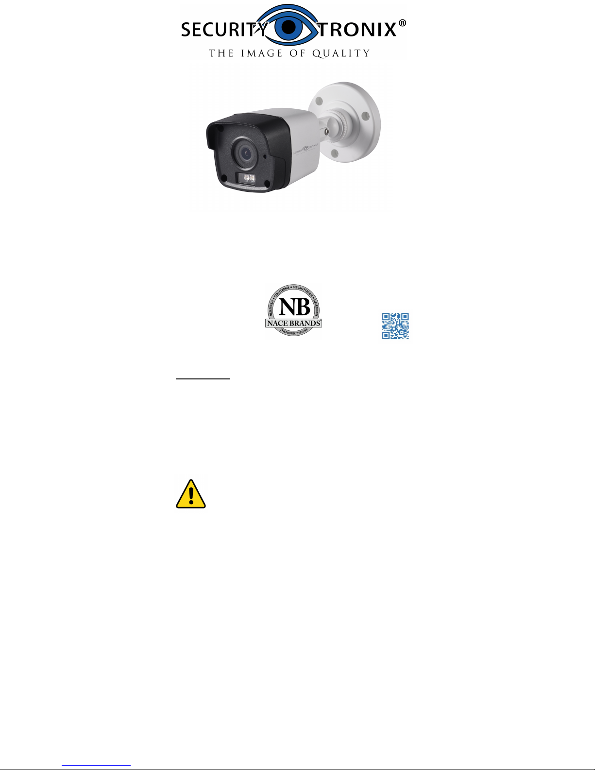
ST-HDC2FB
ST-HDC2FB-2.8
QUICK START GUIDE
www.securitytronix.comwww.nacebrands.com
Page 2
Regulatory Information
FCC Information
Please take attention that changes or modification not
expressly approved by the party responsible for
compliance could void the user’s authority to operate
the equipment.
FCC compliance: This equipment has been tested and
found to comply with the limits for a Class A digital
device, pursuant to part 15 of the FCC Rules. These
limits are designed to provide reasonable protection
against harmful interference when the equipment is
operated in a commercial environment. This equipment
generates, uses, and can radiate radio frequency energy
and, if not installed and used in accordance with the
instruction manual, may cause harmful interference to
radio communications. Operation of this equipment in a
residential area is likely to cause harmful interference in
which case the user will be required to correct the
interference at his own expense.
FCC Conditions
This device complies with part 15 of the FCC Rules.
Operation is subject to the following two conditions:
1. This device may not cause harmful interference.
2. This device must accept any interference received,
including interference that may cause undesired
operation.
EU Conformity Statement
This product and - if applicable - the
supplied accessories too are marked with
"CE" and comply therefore with the
applicable harmonized European
standards listed under the Low Voltage Directive
2014/35/EU, the EMC Directive 2014/30/EU.
2012/19/EU (WEEE directive): Products
marked with this symbol cannot be
disposed of as unsorted municipal waste in
the European Union. For proper recycling,
return this product to your local supplier
upon the purchase of equivalent new
equipment, or dispose of it at designated collection
points. For more information see: www.recyclethis.info.
2006/66/EC (battery directive): This product contains a
battery that cannot be disposed of as
unsorted municipal waste in the European
Union. See the product documentation for
specific battery information. The battery is
marked with this symbol, which may
include lettering to indicate cadmium (Cd), lead (Pb), or
mercury (Hg). For proper recycling, return the battery
to your supplier or to a designated collection point. For
more information see: www.recyclethis.info.
Industry Canada ICES-003 Compliance
This device meets the CAN ICES-3 (A)/NMB-3(A)
standards requirements.
Page 3
Safety Instruction
These instructions are intended to ensure that user can
use the product correctly to avoid danger or property
loss.
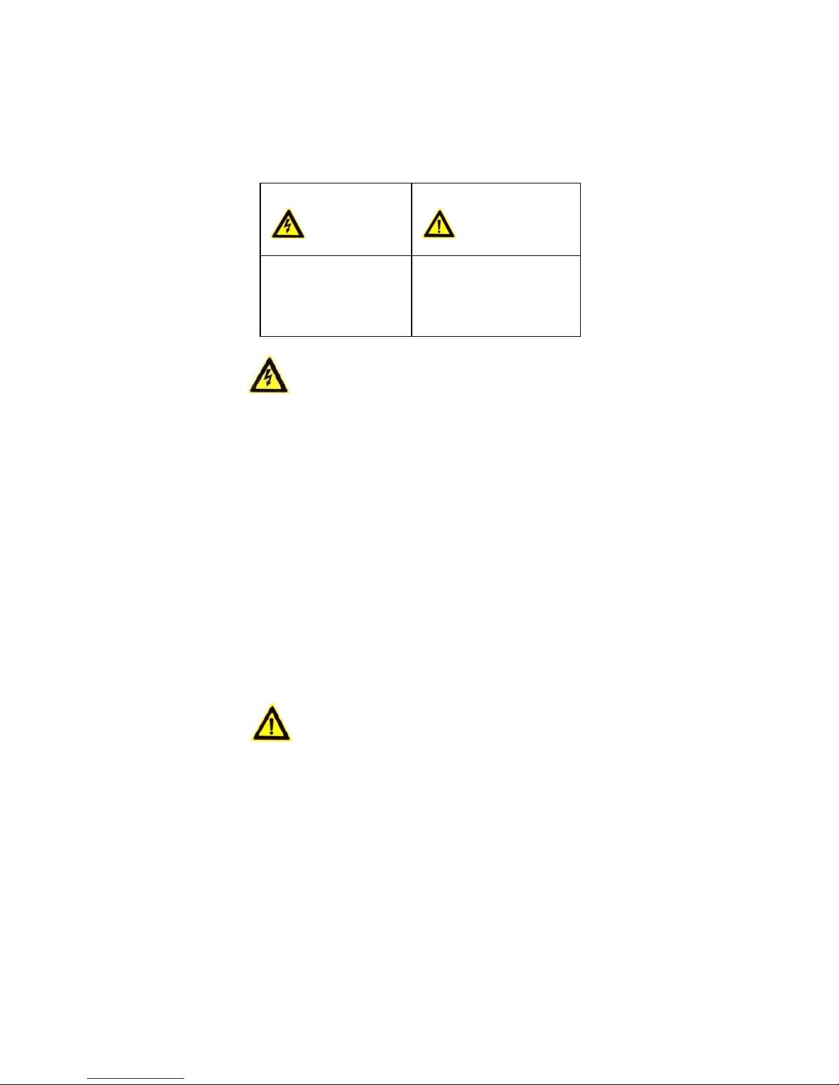
The precaution measure is divided into “Warnings” and
“Cautions”.
Warnings: Serious injury or death may occur if any of
the warnings are neglected.
Cautions: Injury or equipment damage may occur if any
of the cautions are neglected.
Warnings
When using this product, you must be in strict
compliance with the electrical safety regulations of
the nation and region. Please refer to technical
specifications for detailed information.
Input voltage should meet both the SELV (Safety
Extra Low Voltage) and the Limited Power Source
with 12 VDC according to the IEC60950-1 standard.
Please refer to technical specifications for detailed
information.
Do not connect several devices to one power adapter
as adapter overload may cause over-heating or a fire
hazard.
Please make sure that the plug is firmly connected to
the power socket. When the product is mounted on
wall or ceiling, the device should be firmly fixed.
If smoke, odor or noise rise from the device, turn off
the power at once and unplug the power cable, and
then please contact the service center.
Cautions
Make sure the power supply voltage is correct
before using the camera.
Do not drop the camera or subject it to physical
shock.
Do not touch sensor modules with fingers. If
cleaning is necessary, use a clean cloth with a bit of
ethanol and wipe it gently. If the camera will not be
used for an extended period, please cap the lens to
protect the sensor from dirt.
Do not aim the camera at the sun or extra bright
places. Blooming or smearing may occur otherwise
(which is not a malfunction), and affect the
endurance of the sensor at the same time.
The sensor may be damaged by a laser beam, so
when any laser equipment is in use, make sure that
the surface of the sensor will not be exposed to the
laser beam.
Warnings Follow
these safeguards to
prevent serious injury
or death.
Cautions Follow these
precautions to prevent
potential injury or
material damage.
Page 4

Do not place the camera in extremely hot, cold (the
operating temperature should be -22°F to +140°C),
dusty or damp locations, and do not expose it to
high electromagnetic radiation.
To avoid heat accumulation, good ventilation is
required in the operating environment.
Keep the camera away from liquid while in use.
During transport, the camera should be packed in its
original packing, or packing of the same type.
Improper use or replacement of the battery may
result in explosion hazard. Replace with the same or
equivalent type only. Dispose of used batteries
according to the instructions provided by the battery
manufacturer.
If the product does not work properly, please
contact your dealer or the nearest service center.
Never attempt to disassemble the camera yourself.
(We do not assume any responsibility for problems
caused by unauthorized repair or maintenance.)
Page 5

1 Introduction
1.1 Product Features
The camera is applicable for both indoor and outdoor
conditions, and the application scenarios include road,
warehouse, underground parking lot, bar, etc..
The main features are as follows:
High performance CMOS sensor
Low illumination, 0.005 Lux @ (F2.0, AGC ON), 0 Lux
with IR
IR cut filter with auto switch
OSD menu with configurable parameters
Auto white balance
internal synchronization
SMART IR mode
PoC (with -E)
3-axis adjustment
1.2 Overview
Main Body
Photoresistor
Lens
Bracket
Video Cable
Power Cord
12 VDC
Figure 1-1 Overview
2 Installation
Before you start:
Make sure the device in the package is in good
condition and all the assembly parts are included.
The standard power supply is 12 VDC or PoE (802.3
af), please make sure your power supply matches the
camera's.
Make sure all the attached equipment is powered off
during installation.
Make sure that the wall is strong enough to
withstand four times the weight of the camera and
the bracket (if applicable).
If the wall is cement, insert plastic anchors before
installing the camera. If the wall is wooden, use
self-tapping screws to secure the camera.
If the product does not function properly, contact
your dealer or the nearest service center. Do NOT
disassemble the camera for repair or maintenance.
2.1 Ceiling/Wall Mounting without Junction Box
Steps:
1. Stick the drill template (supplied) to the place
where you want to install the camera.
2. Drill the screw holes and the cable hole (optional)
in the ceiling/wall according to the drill template.
Page 6

Template
Cable
Hole
Screw
Hole
Side Opening
Figure 2-1 Drill Template
Note:
Drill the cable hole if planning to route the cable
through the ceiling/wall.
3. Attach the bracket to the ceiling/wall and secure the
camera with the supplied screws.
Fixing Screw
Adjusting Screws
Figure 2-2 Fix the Camera to the Ceiling
Note:
The supplied screw package contains self-tapping
screws, and plastic anchors.
For cement wall/ceiling, plastic anchors are
required to fix the camera. For wooden
wall/ceiling, self-tapping screws are required.
4. Route the cables through the cable hole, or the side
opening.
5. Connect the corresponding power cord, and video
cable.
6. Power on the camera to adjust the viewing angle
(aim). Adjust the camera as needed according to the
figure below to get an optimum angle.
P Screw
T Screw
R Screw
Tilt Position
[0° to 180°]
Pan Position
[0° to 360°]
Rotation Position
[0° to 360°]
Figure 2-3 3-axis Adjustment
1). Loosen the P screw to adjust the pan position [0°
to 360°]. Tighten the screw after completing the
adjustment.
2). Loosen the T screw to adjust the tilt position [0°
to 180°]. Tighten the screw after completing the
adjustment.
3). Loosen the R screw and rotate the camera [0° to
360°]. Tighten the screw after completing the
adjustm
ent.
Page 7

2.2 Ceiling/Wall Mounting with Junction Box
The Junction box is not included in the
package.
Steps:
1. Stick the drill template (supplied) to the
place where you want to install the camera.
2. Drill screw holes and the cable hole in the
ceiling/wall according to the holes of the
drill template.
Figure 2-4 Drill Template of Junction Box
3. Take apart the junction box, and align the screw
holes of the bullet camera with those on the
junction box’ cover.
4. Fix the camera to the junction box’s cover with
the supplied screws.
Junction
Box Cover
Figure 2
-5 Fix the Camera on the Junction Box’s Cover
5. Attach the junction box body to the ceiling/wall by
aligning with the screw holes made using the
template.
6. Secure the junction box’s body to the ceiling/wall
with the supplied screws.
Junction Box
Body
Figure 2-6 Fix the Junction Box to the Wall/Ceiling
7. Route the cables through the bottom cable hole,
or the side cable hole of the junction box.
8. Connect the corresponding power cord, and video
cable.
Page 8

Figure 2-7 Fix junction box cover to body
9. Reattach the junction box cover with
camera to the junction box's body.
10. Adjust the viewing angle (aim).
Refer to step 6 in section 2.1.
3 Menu Description
button in PTZ Control,
Purpose:
Call the menu by clicking the
or call preset No.95.
Steps:
1. Connect the camera with the TVI DVR, and the
monitor, as shown in figure 3-1.
Camera
TVI DVR
Monitor
Figure 3-1 Connection
2. Power on the camera, TVI DVR, and the monitor
3.
4.
5. Click the directional arrows to control the
camera's OSD.
(1) Click up/down direction arrows to navigate
up and down in the menu lists.
(2) Click Iris + to confirm selection.
(3) Click left/right direction button to adjust the
value of selected items.
to view the image on the monitor.
Right-click to access the quick menu, then click PTZ
Control to enter the PTZ Control interface.
Call the camera menu by clicking button, or call
preset No. 95.
Page 9

AE
WB
BRIGHTNESS
MAIN MENU
FORMAT
LANGUAGE
DAY NIGHT
VIDEO
SETTINGS
FUNC
RESET
SAVE & EXIT
PRIVACY
EXPOSURE MODE
AGC
SENSE UP
MODE
RETURN
MODE
RETURN
CONTRAST
SHARPNESS
COLOR GAIN
3D DNR
MIRROR
RETURN
MOTION
CAM ID
RETURN
Figure 3-2 Main Menu Overview
3.1 FORMAT
PAL (Phase Alternating Lines)
PAL is a color encoding system for analog television
used in broadcast television systems in most countries.
NTSC: (National Television System Committee)
NTSC is the analog television system that is used in
most of North America, parts of South America,
Myanmar, South Korea, etc.
3.2 LANGUAGE
Available options are English, and Chinese.
3.3 MAIN MENU
3.3.1 AE (AUTO EXPOSURE)
Auto Exposure describes brightness-related
parameters, which can be adjusted in BRIGHTNESS,
EXPOSURE MODE, AGC, and SENSE UP.
EXPOSURE
BRIGHTNESS 5
EXPOSURE MODE
AGC
SENSE UP 0
RETURN
G L
OBAL
MIDDLE
Figure 3-3 AE
Page 10

BRIGHTNESS
Brightness refers to the brightness of the image.
You can set the brightness value from 1 to 10 to darken
or brighten the image. The higher the value, the
brighter the image is.
EXPOSURE MODE
You can set the EXPOSURE MODE to GLOBAL, BLC, or
WDR.
GLOBAL
GLOBAL refers to the normal exposure mode which
adjusts lighting distribution, variations, and
non-standard processing.
BLC (Backlight Compensation)
BLC (Backlight Compensation) compensates for bright
lights in backgrounds by automatically adjusting
exposure for darker foreground areas and objects.
This may cause over-exposure of the areas where light
is strong. When BLC is selected as the exposure mode,
the BLC level can be adjusted from 0 to 8.
WDR (Wide Dynamic Range)
Wide dynamic range helps the camera provide clear
images even under backlit circumstances. WDR
balances the brightness level of the whole image and
provides clear images with details.
AGC (Auto Gain Control)
AGC optimizes the clarity of the image in poor light
conditions. The GAIN level can be set as HIGH, MIDDLE,
or LOW. Select OFF to disable the GAIN function.
Note:
Image noise will be amplified when the GAIN is on.
SENSE UP
Sense up increases the exposure on a signal frame,
which makes a camera more sensitive to light so it can
produce images even in low lux conditions. You can set
the SENS-UP as OFF or AUTO as desired for different
lighting conditions.
The SENS-UP function will automatically adjust itself to
x2, x4, x6, x8, x10, x12, x14, and x16 according to
different lighting conditions when on AUTO.
3.3.2 WB (White Balance)
White balance is used to to adjust the color
temperature (tints of blues and reds) of the image.,
and can remove unrealistic color casts in the image.
You can set WB mode as ATW, or MWB.
ATW (Auto Tracking White Balance)
Under ATW mode, white balance is adjusted
automatically according to the color temperature of
the image lighting.
MWB (Manual White Balance)
You can set the R GAIN/B GAIN value from 1 to 255 to
adjust the shades of red/blue color of the image.
WB
MODE
R GAIN
B GAIN
RETURN
MWB
5
5
Figure 3-4 MWB MODE
Page 11

3.3.3 DAY NIGHT
Color, BW (Black White), and AUTO are selectable for
DAY NIGHT modes.
COLOR
The image is in color (day mode) at all times.
B/W
The image is black and white (night mode) at all
times, and the IR LED turns on in low-light conditions.
AUTO
You can turn on/off the INFRARED and set the value
of SMART IR in this menu.
DAY NIGHT
MODE
INFRARED
SMART IR
RETURN
AUTO
ON
4
Figure 3-5 DAY NIGHT
INFRARED
You can turn on/off the IR LED(s) to meet the
requirements of different illumination needs.
SMART IR
The Smart IR function is used to adjust the light to its
most suitable intensity, and prevent the image from
over exposure. The SMART IR value can be adjusted
from 1 to 8. The higher the value, the stronger the
effects will be.
3.3.4 VIDEO SETTING
Move the cursor to VIDEO SETTING and click Iris+ to
enter the submenu. CONTRAST, SHARPNESS,
COLOR GAIN, 3D DNR, and MIRROR are adjustable.
VIDEO SETTING
CONTRAST
SHARPNESS
COLOR GAIN
3D DNR
MIRROR
RETURN
5
5
5
5
DEFAULT
Figure 3-6 VIDEO SETTING
CONTRAST
This feature enhances the difference in color and light
between parts of an image. You can set the CONTRAST
value from 1 to 10.
SHARPNESS
Sharpness determines the amount of detail an imaging
system can reproduce. You can set the SHARPNESS
value from 1 to 10.
COLOR GAIN
Adjust this feature to change the saturation of color in
the image. The value ranges from 1 to 10.
3D DNR (Digital Noise Reduction)
The 3D DNR function can decrease image noise
artifacts, especially when capturing moving images in
low light conditions and delivering more accurate and
sharp image quality. You can set the DNR value from 1
to 10.
Page 12

MIRROR
DEFAULT, H, V, and HV are selectable for mirror.
DEFAULT: The mirror function is disabled.
H: The image flips 180° horizontally.
V: The image flips 180° vertically.
HV: The image flips 180° both horizontally and
vertically.
3.3.5 FUNC (Functions)
In the FUNC sub-menu, you can set privacy mask,
motion defection, and camera ID settings.
PRIVACY
The privacy mask allows you to cover certain areas
which you don’t want to be viewed or recorded. Up to
4 privacy areas are configurable.
PRIVACY
MODE
AREA 0
AREA 1
AREA 2
AREA 3
COLOR
TRANSPARENCY
RETURN
ON
RED
OFF
Figure 3-7 PRIVACY
Select a PRIVACY area. Set the DISPLAY status to ON.
Click up/down/left/down buttons to define the
position and size of the area.
MOTION
In user-defined motion detection areas, moving
objects can be detected and recording will be
triggered. Up to 4 motion detection areas can be
configured.
MOTION
MODE
AREA 0
AREA 1
AREA 2
AREA 3
SENSITIVITY
COLOR
TRANSPARENCY
RETURN
OFF
50
RED
OFF
Figure 3-8 MOTION
Select a MOTION area. Set the DISPLAY status to ON.
Click up/down/left/right buttons to define the
position and size of the area. Set the SENSITIVITY from
0 to 100.
CAMERA ID
This setting allows a camera ID number to be
displayed on the screen.
CAM ID SETTING
MODE
CAM ID
X POSITION
Y POSITION
RETURN
ON
75
36
16
Figure 3-9 CAM ID SETTING
Page 13

Set the MODE as on. Click up/down/left/right buttons to
choose the camera ID and the position.
3.3.6 RESET
Resets all settings to their default values.
3.3.7 SAVE & EXIT
Move the cursor to SAVE & EXIT, then click Iris+ to
save settings and exit the menu.
If you have any questions, or requests, please
contact our support department at
1-800-688-9282, Option 3, Option 2.
SECURITYTRONIX 2-Year Limited Fixed Camera Warranty
Securitytronix. (the "Company") warrants to the Original Purchaser that the Fixed
Camera is free from defects in workmanship or material under normal use. This
warranty starts on the date of shipment of the hardware to the Original Purchaser.
During the warranty period, the Company agrees to repair or replace, at its sole
option, without charge to Original Purchaser, any defective component in the Fixed
Camera. To obtain service, the Original Purchaser must return the Fixed Camera to the
Company properly packaged for shipping. All defective products must be returned to
the Company within thirty (30) days of failure. Products must be returned with a
description of the failure and Return Merchandise Authorization (RMA) number
supplied by the Company. To receive a RMA number and a return shipping address on
where to deliver the hardware, call 610-429-1821. The shipping, and insurance charges
incurred in shipping to the Company will be paid by Original Purchaser, and all risk for
the hardware shall remain with the Original Purchaser until such time as Company
takes receipt of the hardware. Upon receipt, the Company will promptly repair or
replace the defective unit, and then return said unit to Original Purchaser, shipping
prepaid. The Company may use reconditioned or like-new parts or units, at its sole
option, when repairing any hardware. Repaired products shall carry the same amount
of outstanding warranty as from original purchase. Any claim under the warranty must
include dated proof of purchase or invoice. In any event, the Company's liability for
defective hardware is limited to repairing or replacing the hardware.
This warranty is contingent upon proper use of the hardware by Original Purchaser
and does not cover: if damage is due to Acts of God (including fire, flood, earthquake,
storm, hurricane or other natural disaster), accident, unusual physical, electrical, or
electromechanical stress, modifications, neglect; misuse, operation with media not
approved by the Company, tampering with or altering of the hardware, war, invasion,
act of foreign enemies, hostilities (regardless of whether war is declared), civil war,
rebellion, revolution, insurrection, military or usurped power or confiscation, terrorist
activities, nationalization, government sanction, blockage, embargo, labor dispute,
strike, lockout or interruption or failure of electricity, air conditioning, or humidity
control, internet, network, or telephone service
The warranties given herein, together with any implied warranties covering the
hardware, including any warranties of merchantability or fitness for a particular
purpose, are limited in duration to two years from the date of shipment to the Original
Purchaser. Jurisdictions vary with regard to the enforceability of warranty limitations,
and you should check the laws of your local jurisdiction to find out whether the above
limitation applies to you.
The Company shall not be liable to your for loss of data, loss of profits, lost savings,
special, incidental, consequential, indirect, or other similar damages arising from
breach of warranty, breach of contract, negligence, or other legal action even if the
Company or its agent has been advised of the possibility of such damages, or for any
claim brought against your by another party. Jurisdictions vary with regard to the
enforceability of provisions excluding or limiting liability for incidental or consequential
damages. You should check the laws of your local jurisdiction to find out whether the
above exclusion applies to you.
This warranty allocates risks of product failure between Original Purchaser and the
Company. The Company's hardware pricing reflects this allocation of risk and the
limitations of liability contained in this warranty. The warranty set forth above is in lieu
of all other express warranties, whether oral or written. The agents, employees,
distributors, and dealers of the Company are not authorized to make modification to
this warranty, or additional warranties binding on the Company. Accordingly,
additional statements such as dealer advertising or presentations, whether oral or
written, do not constitute warranties by the Company and should not be relied upon.
This warranty gives you specific legal rights. You may also have other rights which vary
from one jurisdiction to another.
 Loading...