

Page 1
INSTALLATION MANUAL
www.nacebrands.com www.securitytronix.com
Professional Motorized Varifocal Camera
ST-HD-BT2812M-2MP
Page 2
1
Description:
The ST-HD-BT2812M-2MP is a professional-grade bullet color camera
with IR and motorized zoom capabilities, and 1080p resolution. A
2.8mm to 12mm motorized lens makes zooming and focusing during
installation fast and simple, and its ability to send HD video over
coaxial cable makes the ST-HD-BT2812M-2MP a cost effective highdefinition surveillance solution for any budget.
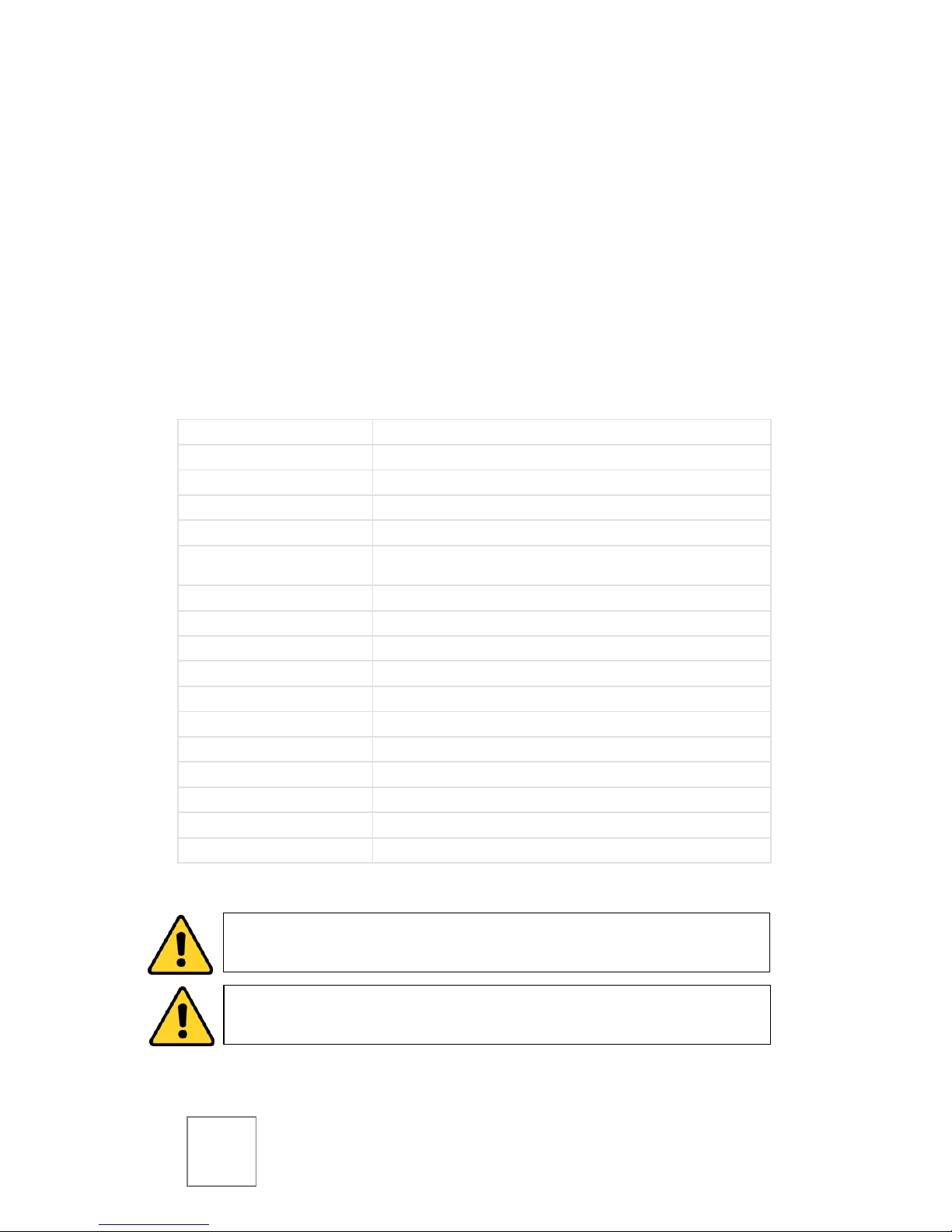
Specifications:
Image Sensor
1/2.8” CMOS
Resolution
1920(H) x 1080(V) @25fps
Scanning System
Progressive
Auto Electronic Shutter
1/3s ~ 1/100,000s
Minimum Illumination
0.05Lux@F1.2; 0Lux (IR on)
Video Output
1-channel BNC HD-CVI high definition video output / CVBS standard definition
video output (Can switch)
Day/Night
Auto(ICR) / Color / B/W
Noise Reduction
2D/3D
Lens
2.8mm - 12mm, Motorized
IR LED
φ5x24PCS
IR Distance
Up to 98 feet
Power Supply
DC12V 1A
Power Consumption
7.5W (IR on)
Working Environment
-20°f ~ 133°f / Less than 95% RH
Ingress Protection
IP66
Dimensions
8.4”x3.2”x2.9”
Weight
1.25lbs
CAUTION: To reduce the risk of electrical shock do not open this unit.
No user serviceable parts are inside.
CAUTION: To prevent electric shocks and risk of fire hazards, do not
use other than specified power source.
Page 3

2
Unpacking
Package Contents:
(1) ST-HD-BT2812M-2MP Motorized Varifocal IR Camera
(1) Installation Manual
Note: The ST-HD-BT2812M-2MP requires a 12VDC 1A power supply such
as the ST-PS12VDC1A.
Ensure that all accessories and documentation are removed from the
container before discarding packing material.
Inspect the front, sides, and rear of the equipment for shipping
damage. Make sure the equipment is clean, and no connectors are
broken, damaged, or loose. If equipment appears to be damaged or
defective please contact your distributor or SecurityTronix at:
(800) 688-9282, press 3 for tech support, then press 2 for CCTV.
Setup & Installation
!! ATTENTION !!
The installer must comply with electrical safety standards.
There must be sufficient space between the camera’s power
supply and video line and any high voltage equipment and/or
cables.
To help ensure the camera’s life and proper operation do not
point the camera towards the sun or strong light.
Do not install the camera in an environment where the
temperature is above 130°f.
Do not install the camera near a magnetic field or a high-
power motor.
Do not mount the camera near a radiator or heater.
The installation site and material must fully support the
weight of the product.
Page 4

3
Only use a dry cloth to clean the camera. If there is dirt that is
difficult to remove wipe gently with a mild detergent. Never
use strong or abrasive detergents.
A 12VDC power supply must be used. Using an AC or other
incorrect power supply will damage the camera.
Only qualified installers are allowed to install and test the
camera.
The camera is a low voltage product. If installed outdoors
proper safety and lightning grounding are required.
Be sure the grounding, wiring, input power, and voltage are
correctly set prior to powering up and using.
Making Connections
1. Connect the DC power supply cable to the camera’s power
connector.
2. Connect the camera to the CVR with a 75Ω coaxial video
cable.
3. Connect power supply’s AC plug to a suitable AC power
outlet.
Page 5

4
Zoom & Focus
The ST-HD-BT2812M-2MP features motorized zoom and focus, and is
controlled from the CVR via COC (control over coax).
Using the on-screen PTZ controller of the CVR, press the ZOOM -/+
buttons to reach the desired level of zoom. The camera will then autofocus. If fine-tuning of focus is necessary, press the FOCUS -/+ buttons
until the desired focus is achieved.
Switching to Analog Output
If SD (standard definition) analog output is desired, disconnect power
from the camera, then connect the labeled brown and white wires on
the camera to each other before powering the camera back on.
To switch back to HD-CVI output, disconnect power from the camera,
and disconnect the labeled brown and white wires on the camera
from each other before powering the camera back on.
On-Screen Display
To enter the OSD, click the MENU OPEN button on the CVR’s on-
screen PTZ controller, then click ENTER. Navigate the OSD using the
PTZ controller’s up, down, left, and right arrows. Confirm selections by
pressing ENTER.
Page 6

5
Troubleshooting
Issue
Solution
No picture after applying
power.
(1) Check that all plugs and cables are securely connected
to the proper connectors.
(2) Ensure that the power supply is providing the correct
voltage and current.
Picture is consistently
tinted or distorted.
(1) Check that the coaxial video cable from the camera to
the CVR is securely connected at both ends.
(2) Connect the camera to an alternate working coaxial
video cable between the camera and CVR.
(3) Re-terminate the coaxial video cable between the
camera and CVR with new BNC connectors.
Picture has ripples or
rolling lines.
(1) Check to see if the power supply is experiencing AC
ripple; if so, a filter may be required. (2) Determine if the
monitor is faulty. (3) Determine if other peripheral
equipment is causing ripple, and if so, make the necessary
adjustments.
The picture is tinted /
continuously changing
Colors.
Fluorescent lights’ magnetic field may cause color roll. (1)
Check that the coaxial video cable between the camera
and CVR is not too close to fluorescent lights; increase
distance as needed. (2) Reduce the number of fluorescent
lights near the camera.
For further assistance and troubleshooting, please contact
SecurityTronix tech support at:
(800) 688-9282, press 3 for Tech Support, then press 2 for CCTV.
Page 7

6
Page 8

7
Version 1.1 (4/10/15)
© 2015 North American Cable Equipment.
 Loading...