

Page 1
INSTALLATION MANUAL
www.nacebrands.com www.securitytronix.com
Professional Pan Tilt Zoom Camera
ST-HD-IRPTZ-2MP
Page 2
1
Description:
The ST-HD-IRPTZ-2MP is a professional-grade intelligent dome color
camera with IR and Pan/Tilt/Zoom (PTZ) capabilities, and 1080p
resolution. The camera is designed to function with HD-COAXINATOR™
recorders to utilize Control Over Coax (COC) without the need for an
additional RS485 connection.
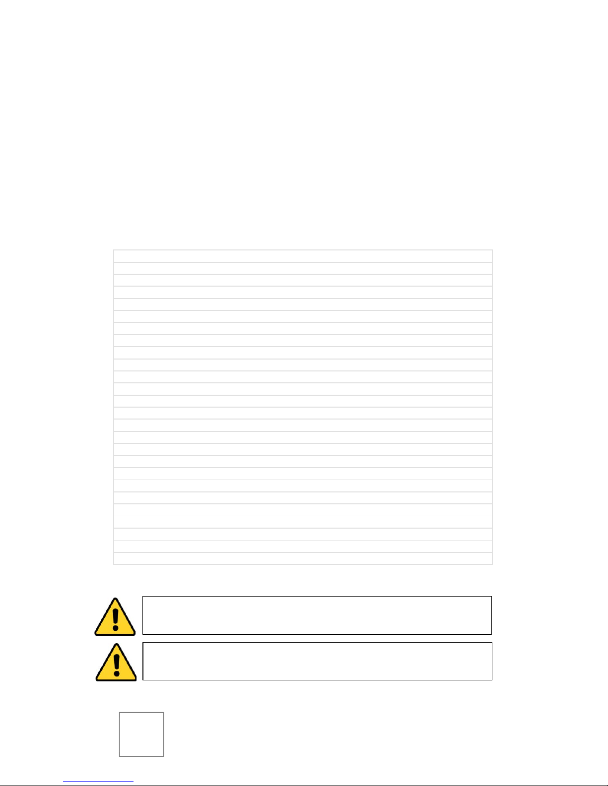
Specifications:
Image Sens or 1/2.8” Exmor CMOS
Resolution
1920(H) x 1080(V) @25fps
Scanning Sys tem Progressive
Auto Electr onic Shutter
1/1 ~ 1/30,000s
Minimum Ill umination Color: 0.05Lux@F1.6; B/W: 0.005Lux@F1.6; 0Lux (IR on)
Signal to Noise Ratio
> 50dB
Video Outp ut
1-channel BN C HDCVI high definition video output / CVBS standar d definition video output (Can switc h)
Day/Night Auto(ICR) / Color / B/ W
Backlight Compensation
BLC / HLC / DWDR (Dig ital WDR)
White Balanc e Auto, ATW, Indo or, Outdoor, Manual
Gain Control
Auto / Manual
Noise Reduction 2D/3D
Lens
4.3mm - 129mm
Pan/Tilt Range Pan: 0° ~ 360° endless / Tilt: -15° ~ 90°, auto flip 180°
Pan Speed
160° /sec
Protocol DH-SD, Pelc o-P/D (Auto recognition)
IR Distance
100m (2 near IR LED+ 4 far IR LED)
Alarm 2/1 channel In/O ut
Power Supply AC 24V/3A
Power Cons umption
10.5W, 26W (IR on, Heater on)
Working Envir onment -30°f ~ 130°f / Less than 90% RH
Ingress Protection
IP66
Dimensions Φ8” x 14.25”
Weight
16.5lbs
Default Addr ess 1
Default Baud Rate
9600
CAUTION:
To reduce the risk of electrical shock do not remove the
cover or back of this unit. No user serviceable parts are inside.
CAUTION: To prevent electric shocks and risk of fire hazards, do not
use other than specified power source.
Page 3

2
Unpacking
Package Contents:
(1) ST-HD-IRPTZ-2MP High-Speed IR Color Camera
(1) Wall Mounting Bracket
(1) Safety Hook
(1) 24V AC Power Supply
(1) Installation Manual
Ensure that all accessories and documentation are removed from the
container before discarding packing material.
Inspect the front, sides, and rear of the equipment for shipping
damage. Make sure the equipment is clean, and no connectors are
broken, damaged, or loose. If equipment appears to be damaged or
defective please contact your distributor or SecurityTronix at:
(800) 688-9282, press 3 for tech support, then press 2 for CCTV.
Setup & Installation
!! ATTENTION !!
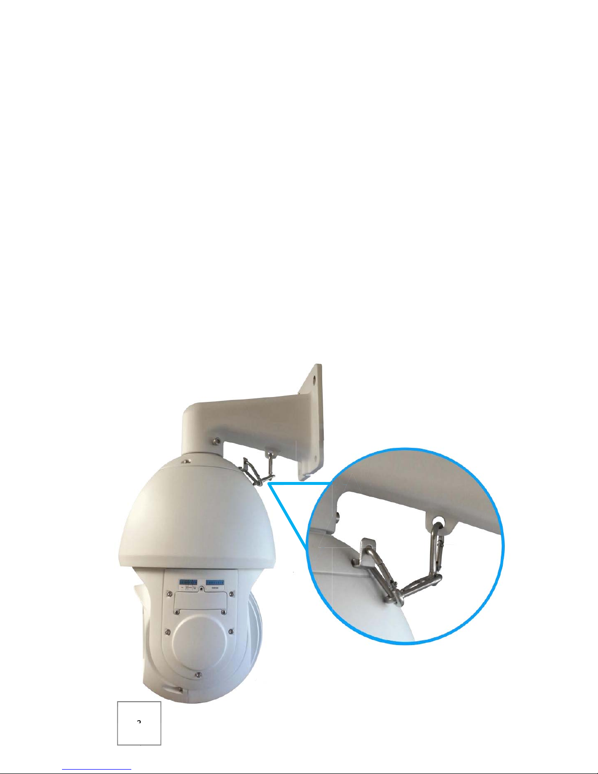
Be sure that all three screws that attach the camera to the
mounting bracket are tightened securely.
Be sure that the safety hook is securely connected to the
attachment points on both the camera body and mounting
bracket.
(see image on following page)
The installer must comply with electrical safety standards.
There must be sufficient space between the camera’s power
supply and video line and any high voltage equipment and/or
cables.
To help ensure the camera’s life and proper operation do not
point the camera towards the sun or strong light.
Do not install the camera in an environment where the
temperature is above 130°f.
Page 4
3
Do not install the camera near a magnetic field or a high-
power motor.
Do not mount the camera near a radiator or heater.
The installation site and material must fully support the
weight of the product.
Only use a dry cloth to clean the camera. If there is dirt that is
difficult to remove wipe gently with a mild detergent. Never
use strong or abrasive detergents.
The included 24VAC power supply must be used. Using a DC
or other incorrect power supply will damage the camera.
Only qualified installers are allowed to install and test the
camera.
The camera is a low voltage product. If installed outdoors
proper safety and lightning grounding are required.
Be sure the grounding, wiring, input power, and voltage are
correctly set prior to powering up and using.
Page 5

4
Making Connections
1. Connect the AC power supply cable to the camera’s power
leads.
2. Connect the camera to the CVR with a 75Ω coaxial video
cable.
3. (Optional) Connect unshielded twisted pair (UTP) control
cable between the camera’s labeled RS485 leads and the PTZ
controller. Be sure wire polarities (+/-) are the same at each
connection.
4. Connect power supply’s AC plug to a suitable AC power
outlet.
Operation
Default Address: 1
Default Baud Rate: 9600
Setting Address
On your PTZ controller, CALL preset 95 to enter the OSD MENU. The
symbol will indicate your current selection. Using the joystick or
up/down arrows, navigate to SYSTEM SETTING and press OPEN to
enter.
Page 6

5
Navigate to ADDR INFORMATION and press OPEN to enter.
Change ADDR TYPE to SOFT by moving left or right using your PTZ
controller. Next, navigate to ADDR-SOFT and set your desired address
by moving right to increase, or left to decrease.
Once the desired address has been set, navigate to SAVE and press
OPEN to save the address settings. Finally, navigate to EXIT and press
OPEN on your PTZ controller to exit the OSD MENU.
Basic Operation
The table below is a quick guide to the camera’s basic operations using
a PTZ controller.
Function Operation
Pan/Tilt Move joystick or press arrows left, right, up, or down.
Zoom Out Press WIDE or rotate the joystick counter-clockwise for the
desired image.
Zoom In Press TELE or rotate the joystick clockwise for the desired
image.
Focus Near Press NEAR until there is a clear image.
Focus Far Press FAR until there is a clear image.
Note: the camera will attempt auto-focus after being panned, tilted, or zoomed.
Enter OSD Menu CALL Preset 95
Confirm Menu Selection Press OPEN
Set Left Point WRITE Preset 92
Set Right Point WRITE Preset 93
Begin Left/Right Scan CALL Preset 99
End Left/Right Scan Move joystick or press arrows left, right, up, or down.
Page 7

6
Setting a Tour
After PRESET locations have been set, enter the OSD MENU, then use
the joystick or up/down arrows to navigate to FUNCTION SETTING and
press OPEN to enter. Next, navigate to TOUR and press OPEN.
Using the controller’s joystick or arrow buttons, move left or right at
TOUR NO to select the desired tour to edit, then navigate to SETTING
and press OPEN.
Use the joystick or arrow buttons to navigate tour positions. Up and
down will cycle through the positions currently displayed on screen,
and left and right will cycle through pages of positions.
Once a tour position is selected (indicated by the symbol), press
OPEN to edit the tour position’s parameters. Move the joystick left
and right to choose which parameter to edit, or up and down to
change parameter values.
Page 8

7
PRESET indicates which preset number will be called for the
tour position.
DWELL indicates the amount of time the camera will spend at
the tour position.
SPEED indicates the speed that the camera will move to the
next tour position.
Press OPEN to return to position selection.
Enter the parameters for desired tour positions in order starting at 1.
Up to 32 tour positions may be assigned per tour. Any positions left
with PRESET 000 will not be included in the tour.
Once all desired tour positions have been configured. Navigate to
BACK and press OPEN to return to the TOUR menu.
To begin the tour: make sure that the desired TOUR NO is
selected, then navigate to CALL, and press OPEN. The tour
will begin, and no further steps are needed. The OSD menu
will disappear from the screen after a few moments.
To end a running tour: simply move the controller’s joystick
or directional buttons left, right, up, or down.
Troubleshooting
Issue Solution
No picture after applying
power.
(1) Check that all plugs and cables are securely connected
to the proper connectors.
(2) Ensure that the power supply is providing the correct
voltage and current.
Picture is consistently
tinted or distorted.
(1) Check that the coaxial video cable from the camera to
the CVR is securely connected at both ends.
(2) Connect the camera to an alternate working coaxial
video cable between the camera and CVR.
(3) Re-terminate the coaxial video cable between the
camera and CVR with new BNC connectors.
Picture has ripples or
rolling lines.
(1) Check to see if the power supply is experiencing AC
ripple; if so, a filter may be required. (2) Determine if the
monitor is faulty. (3) Determine if other peripheral
equipment is causing ripple, and if so, make the necessary
adjustments.
The picture is tinted / Fluorescent lights’ magnetic field may cause color roll. (1)
Page 9

8
continuously changing
Colors.
Check that the coaxial video cable between the camera
and CVR is not too close to fluorescent lights; increase
distance as needed. (2) Reduce the number of fluorescent
lights near the camera.
Power and video are on,
but the controller does
not move the camera.
(1) Check to ensure that the controller is set to the baud
rate, address, and protocol of the camera. (2) Check to
ensure that the RS485 connections at the camera and the
PTZ controller have the same polarity. (3) Check the
integrity and continuity of the unshielded twisted pair
(UTP) control cable.
For further assistance and troubleshooting, please contact
SecurityTronix tech support at:
(800) 688-9282, press 3 for Tech Support, then press 2 for CCTV.
Page 10

9
Page 11

10
Page 12

11
Version 1.0 (3/25/15)
© 2015 North American Cable Equipment.
 Loading...