

Page 1
INSTALLATION MANUAL
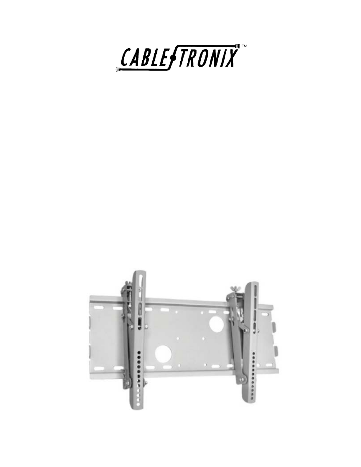
CT-PLB-18
Wall Mount for 23” to 36” Plasma or LCD
Television/Monitor
1
Page 2
PACKAGE CONTENTS
This package contains:
One CT-PLB-18 Wall Mount
Installation accessories (see back page for list of all parts)
Installation Manual
PRODUCT DESCRIPTION
The CT-PLB-18 is a wall mount designed to support 23” to 36” LCD or Plasma televisions/monitors
with a maximum weight of 165 lbs. Made of steel and in a silver finish the CT-PLB-18 has a 0° to
15° adjustable tilt. Measurements are approximately 20.1” wide and 2.96” to 13” high (adju stable).
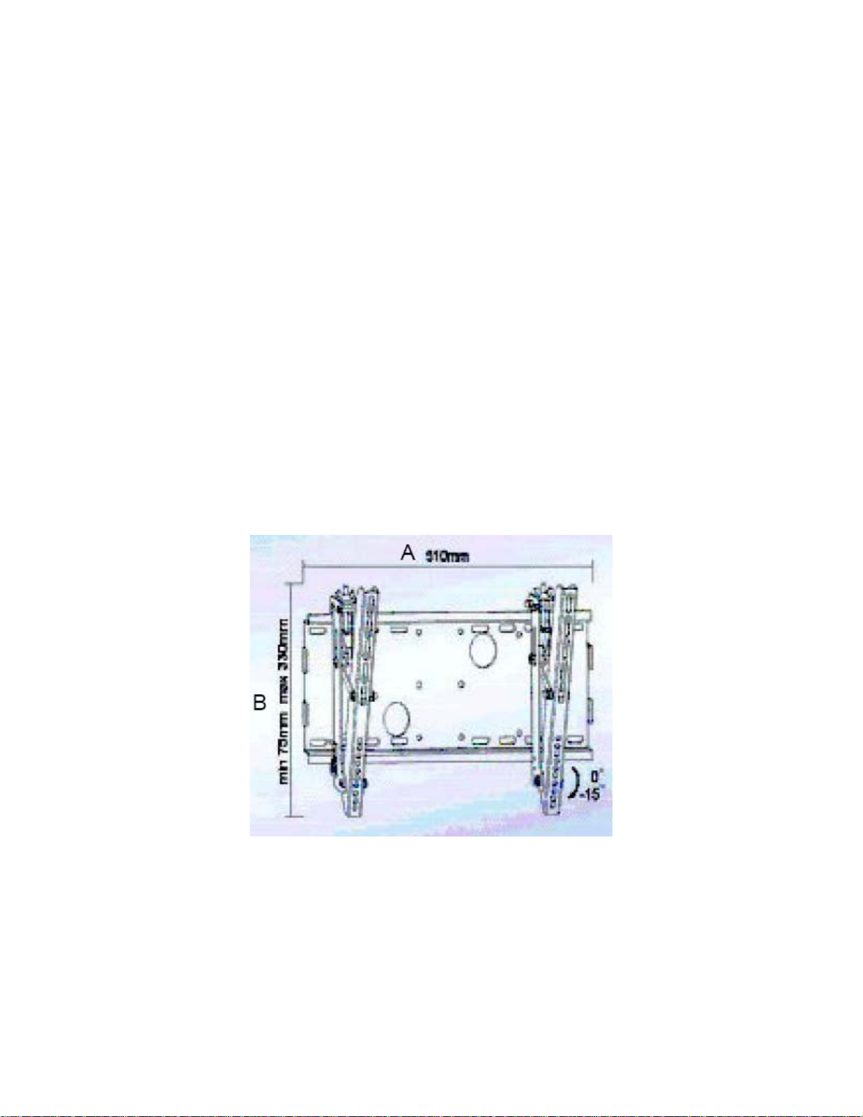
SPECIFICATIONS
The diagram below represents dimensions and articulating range of the CT-PLB-18.
2
Page 3

INSTALLATION
NOTE TO INSTALLER
Warning: The installer of this product must verify that
the mounting surface will safely support the combined
weight of all attached equipment and hardware.
Improper installation may cause damage or serious
injury. The included hardware is for mounting on walls
with wood stud, concrete, or concrete block
construction for a secure, stable, and reliable
mounting. If you are uncertain about the nature of
your wall, consult an expert. Please consult your
hardware or installation professional for proper
mounting to other types of walls. The supplied
hardware is not for steel. North American Cable
Equipment, Inc. will not be held liable for the improper
use or installation of this product.
1. UNPACKING and HANDLING
Each unit is shipped with all necessary mounting hardware.
Ensure that all accessories are removed from the container before discarding packing material
2. MECHANICAL INSPECTION
Inspect the product for shipping damage. Make sure the equipment is clean and damag e free.
If equipment appears to be damaged or defective please contact us at 1-610-429-1511 for
assistance. Never use defective parts.
3. INSTALLATION
Brick, Solid Concrete and Concrete Block Mounting
Use the Wall Plate (A) as a template to mark 6 hole locations on the wall. The outer holes must
fall to left and right of the two large holes in the middle of the plate. Three in the top row slots
and three more in the bottom row. Make sure these holes are level and there is at least 200mm
(7.87 inches) between any two holes. Pre-drill these holes with a 10mm masonry bit to at least
60mm (2.4 inches) in depth. Insert a Concrete Anchor (F) into each of these holes. Pre-drill
these holes with a 5mm (0.20 inch) flush with the concrete surface even if there is a layer of
drywall or other material in front. Attach the Wall Plate using 6 Lag Bolts (E) and 6 M4/M5
Washers (D).
3
Page 4

Dry Wall With Wood Studs
The Wall Plate (A) MUST be mounted to two wood studs. Use a high quality stud sensor to
locate two adjacent studs. It is a good idea to verify where the studs are located with an awl or
thin nail shown in diagram 1-A below. Pre-drill a 3mm (0.12 inch) deep hole at the desired
height in each stud using a 4mm drill bit. Make sure these holes are level. Use the Wall Plate as
a template to mark the location of the second hole in each stud. Pre-drill two holes using the
4mm drill bit as well. Attach the Wall Plate to the wall using 4 Lag Bolts (E). Make sure the Wall
Plate is oriented so the flat surface in the center of the plate is against the wall shown in
diagram 1-B.
Diagram 1-A
Diagram 1-B
4
Page 5

Mount TV Rails To The Back of Your Flat Panel TV/Monitor
Make sure the TV Rails (B and C) are mounted at an equal distance from the top of the
TV/monitor, and close to the center as possible as shown in diagram 2-A below. Knobs should
face the outside of the television. M4, M5, M6, and M8 bolts are provided. Other sizes are
available at your local hardware store. Plastic Spacers (I) are p rovided for use with M4, M5, M6,
and M8 bolts. TV mount bolts on TVs with curved or recessed back panels as shown in diagram
2-B. If you are mounting to a television/monitor with a flat back you will not need a plastic
spacer as shown in diagram 2-C. Make sure these bolts are right! Some televisions and
monitors have shallow threaded inserts. We have provided 4 extra washers you may use to
offset this if the provided bolts are too long.
Diagram 2-A Diagram 2-B Diagram 2-C
Hang the TV Onto The Wall Plate
Hook the TV Rails (B and C) over the top of the Wall Plate (A) as shown in diagram 3-A. Then
tighten the safety screws. Finally loosen the wing nuts and you are free to adjust your flat panel
TV/monitor as shown in diagram 3-B.
Diagram 3-A Diagram 3-B
5
Page 6

Diagram 4-A: Front View of assembled mount Diagram 4-B: Safety Screws tightened
For assistance contact Cabletronix sales engineers at 1-610 -429-1511.
SUPPLIED PARTS
6
 Loading...