

Page 1

Thank you for purchasing our product.
Please read this User’s Manual before
using the product. Change without Notice
8/16 Channel MPEG4 Digital Video Recorder
User’s Manual for model numbers:
DVR8MP4
DVR16MP4
Page 2
-
2
SPECIFICATION
CAUTION
RISK OF ELECTRICAL
SHOCK. DO NOT OPEN !
CAUTION: TO REDUCE THE RISK OF ELECTRICAL SHOCK,
DO NOT REMO VE COV ER (OR BA CK) , NO USER
SERVIC EABL E PARTS REFER SE RVIC ING TO
QUALIFIED S ERVI CE PER SONN EL.
Safety Precautions
The lightning flash with arrowhead symbol, within an equilateral
triangle, is intended to alert the user to the presence of insulated
dangerous Voltage within the product’s enclosure that may be
sufficient magnitude to constitute risk of electrical shock to persons.
The exclamation point within an equilateral triangle is intended to alert
the user to the presence of important operation and maintenance
(servicing) instructions in the literature accompanying the appliance.
WARNING: TO PREVENT FIRE OR SHOCK HAZARD, DO NOT EXPOSE UNITS NOT
SPECIFICALLY DESIGNED FOR OUTDOOR USE TO RAIN OR MOISTURE.
Attention: installation should be performed by qualified service
Personnel only in accordance with the National Electrical Code or
applicable local codes.
Power Disconnect. Units with or without ON-OFF switches have
power supplied to the unit whenever the power cord is inserted into
the power source; however, the unit is operational only when the ON-
OFF switch is the ON position. The power cord is the main power
disconnect for all unites.
There are no serviceable parts for this unit, call for your agent for
details.
Warranty and
Service
Page 3

-
3
SPECIFICATION
Before installing stand alone DVR, be sure to thoroughly review and follow the instructions in this Users Manual.
Pay particular attention to the parts that are marked NOTICE.
Also, when connecting with external application, first turn the power OFF and follow manual
instruction for appropriate installation.
1. This document is intended for both the administrator and users of stand alone DVR Model.
2. This manual contains information for configuring, managing and using stand alone DVR Model.
3. To prevent fire or electrical shock, do not expose the product to heat or moisture
4. Be sure to read this manual before using stand alone DVR Model.
5. For questions and technical assistance of this product, contact your local dealer.
►Strong recommendation on installation of the DVR unit
1. Check electricity at the place you want to install the DVR unit is stable and meets our electricity requirements.
Unstable electricity will cause malfunction of the unit or give critical damage to the unit.
2. Several chips on the main board of the DVR unit and hard disk drive inside the unit generate heat, and it must
be properly discharged.
Do not put any objects just beside exhaust port(fan) on the left side of the unit and do not close up an
opening (fresh air in-take) on the right side of the unit..
3. Put the DVR unit at well-ventilated place and do not put heat-generating objects on the unit.
When it is installed inside 19 inch mounting rack together with other devices, please check built-in ventilation
fan of the rack is properly running.
About this document
Before reading this document
Page 4

-
4
SPECIFICATION
FCC Statement:
WARNING
This device complies with Part 15 FCC Rules. Operation is subject to the following two conditions: (1) This
device may not cause harmful interference. (2) This device must accept any interference received including
interference that may cause undesired operation."
* Federal Communications Commission (FCC) Statement
WARNING
This Equipment has been tested and found to comply with the limits for a Class B digital device, pursuant to
Part 15 of the FCC rules. These limits are designed to provide reasonable protection against harmful
interference in a residential installation. This equipment generates, uses and can radiate radio frequency
energy and, if not installed and used in accordance with the instructions, may cause harmful interference to
radio communications. However, there is no guarantee that interference will not occur in a particular
installation. If this equipment does cause harmful interference to radio or television reception, which can be
determined by turning the equipment off and on, the user is encouraged to try to correct the interference by
one or more of the following measures:
- Reorient or relocate the receiving antenna.
- Increase the separation between the equipment and receiver.
- Connect the equipment into an outlet on a circuit different from
that to which the receiver is connected.
- Consult the dealer or an experienced radio/TV technician for help.
* You are cautioned that changes or modifications not expressly
approved by the party responsible for compliance could void your
authority to operate the equipment.
Page 5
-
5
SPECIFICATION
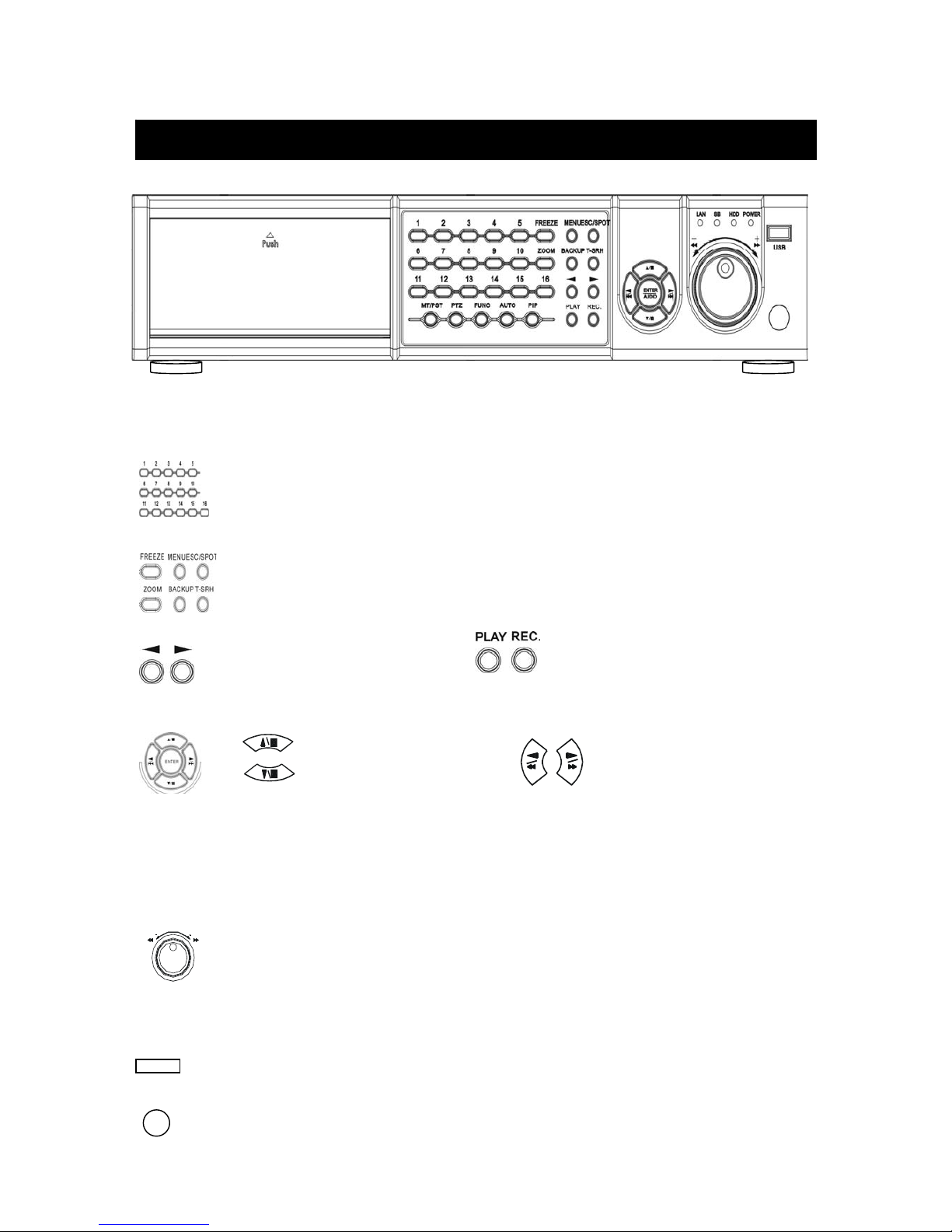
MT / PST: Multi screen select / PTZ preset function. PTZ: PTZ control mode.
FUNC: System information. AUTO : Channel auto sequence. PIP: main and sub screen mode
FUNC + 1 = Audio 1 ON Æ MT split screen button / 1 ~ 16 numeric button = Audio OFF
FUNC + 2 = Audio 2 ON Æ MT split screen button / 1 ~ 16 numeric button = Audio OFF
FUNC + 3 = Audio 3 ON Æ MT split screen button / 1 ~ 16 numeric button = Audio OFF
FUNC + 4 = Audio 4 ON Æ MT split screen button / 1 ~ 16 numeric button = Audio OFF
LED Status : Networking / DVR stand by / HDD operating / DVR power on
USB :Data backup or firmware update
Remote controller IR
1 ~ 16 full screen
FREEZE / MENU / ESC/SPOT
ZOOM / BACKUP / T-SRH
Value change button
Playback / Record
Direction UP / Down,
Record and play stop,
Playback pause / steps.
Direction Left / Right
Playback forward or reverse.
Playback forward / reverse
Function item chan
g
e shuttle.
Unit Description of Front Panel
Page 6
-
6
SPECIFICATION
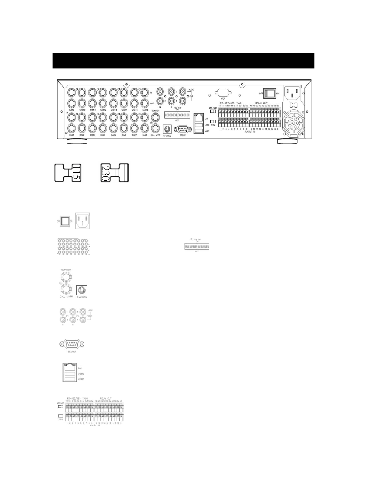
REAL PANEL COMMENTARY ABOUT A.C. POWER SWITCH
Before operation, please verify the working voltage to be 110 or 220 VAC. Adjust the power switcher at the
rear panel to the correct location. Activate the power switch to on and you are ready for operation.
Camera 1 ~ 16 in and
looping out
Main / Call monitor
S-Video (Y/C) monitor
Audio in x 4 / out x 2
RS-232
75 Ohm ON/OFF
(High/low adjust)
LAN port
USB port
Power cord in 12V/5A, power switcher (ON / OFF)
Unit Description of Rear Panel
RS 422 / 485 switcher, interface
Terminator
Alarm in / Relay
Page 7
-
7
SPECIFICATION
DEVICE CONTROLS
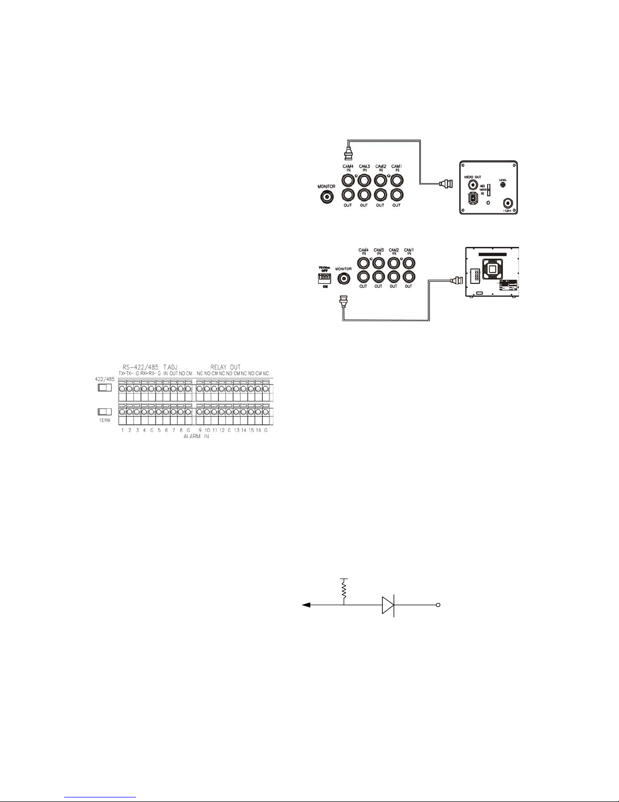
1) Camera Connection
Connect camera to the CAMERA INPUT
located at rear side of the DVR.
2) Monitor Connection
(Composite Connection Method)
Connect monitor to the MONITOR output
located at rear side of the DVR.
3) Alarm in and Relay out
Relay output : COM+NC, COM+NO
Alarm input : Short-circuit between Alarm1 ~ 16 and GND is recognized as alarm by default.
Alarm 1 ~ 16 will be corresponding to Camera 1 ~ 16.
NC = Normal Close. NO = Normal Open.
NOTICE: Sensor input is RECOGNIZED as LOW when alarm signal is on a level with GND, and it is recognized
as HIGH when alarm signal is FLOATING or 5V. Following is internal circuit.
Thus, there is a danger of damage, when the sensor input goes to a Negative level or voltage higher than 5V.
Internal Circuit
D1
5
V
Page 8
-
8
SPECIFICATION
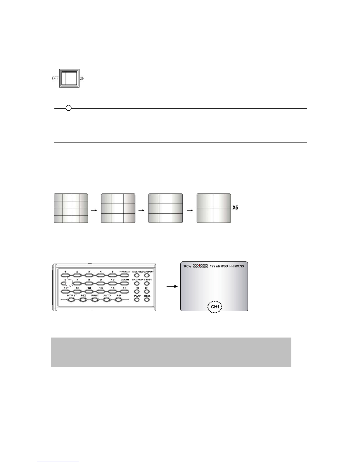
POWER ON /OFF
After the connection of power cord and other devices with this DVR, turn the power on.
a. The video signal system (NTSC or PAL) is automatically detected.
b. Power Failure Recovery. This DVR automatically reverts back to programmed record
parameters upon power restoration.
c. If the power key is protected by password, the power on/off cannot be executed before input the
correct password.
(Refer to the PASSWORD in the SYSTEM menu)
CHANNEL DISPLAY
Full screen or split screen display
a. Multi display
16 9A 9B 4A~4E
To change a single camera display to the multi camera, press the MULTI button.
b. Full screen display
Press the desired camera number button to display on the monitor.
• Before the power of this DVR is on, check the input power currency in advance and select the indication of power
input (230V=180V~265V, 115V=90V~135VAC)at the rear side of DVR
• If there is no video signal, the video signal system is set to NTSC. Do not input the PAL type video signal or it may
cause the DVR’s malfunction. In this case, turn off and on again.
Use the +10 Button when you select two digit camera numbers.
EX) Camera Number 12 = Press the +10 Button, and then press the No. 2 Button.
CAMERA/NUMBER INPUT buttons are used to input the password in the password lock function.
Page 9
-
9
SPECIFICATION
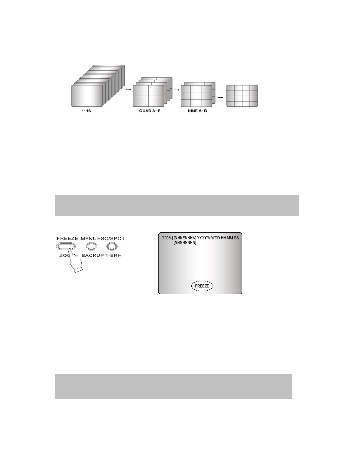
Auto Sequence Display
<ADD AUTO SINGLE: ON>
- Press the AUTO button, each screen display will be automatically switching according to the AUTO
SEQUENCE setup.
- If you set up “ADD AUTO SINGLE: OFF” in the AUTO SEQUENCE setup menu, the single display will be
skipped.
- To view the single display, set up “ADD AUTO SINGLE: ON” in the AUTO SEQUENCE setup menu and the
single display will be included in the auto sequence display.
- Press the AUTO button again to exit the AUTO mode.
Freeze
MULTI SCREEN MODE
At the Multi display mode, press the FREEZE button and then select the desired camera number.
Press the FREEZE button again to release the FREEZE mode.
SINGLE SCREEN MODE
Press the FREEZE button after the desired channel is selected.
Press the FREEZE button again to release the FREEZE mode.
- If you press the MULTI button after pressing the FREEZE button, all the channels will
display still images.
- FREEZE function is not available, when auto mode is selected.
If an event takes place, the AUTO SEQUENCE mode will be cancelled.
Please refer to the AUTO SEQUENCE of MENU setup for more information.
Page 10
-
10
SPECIFICATION
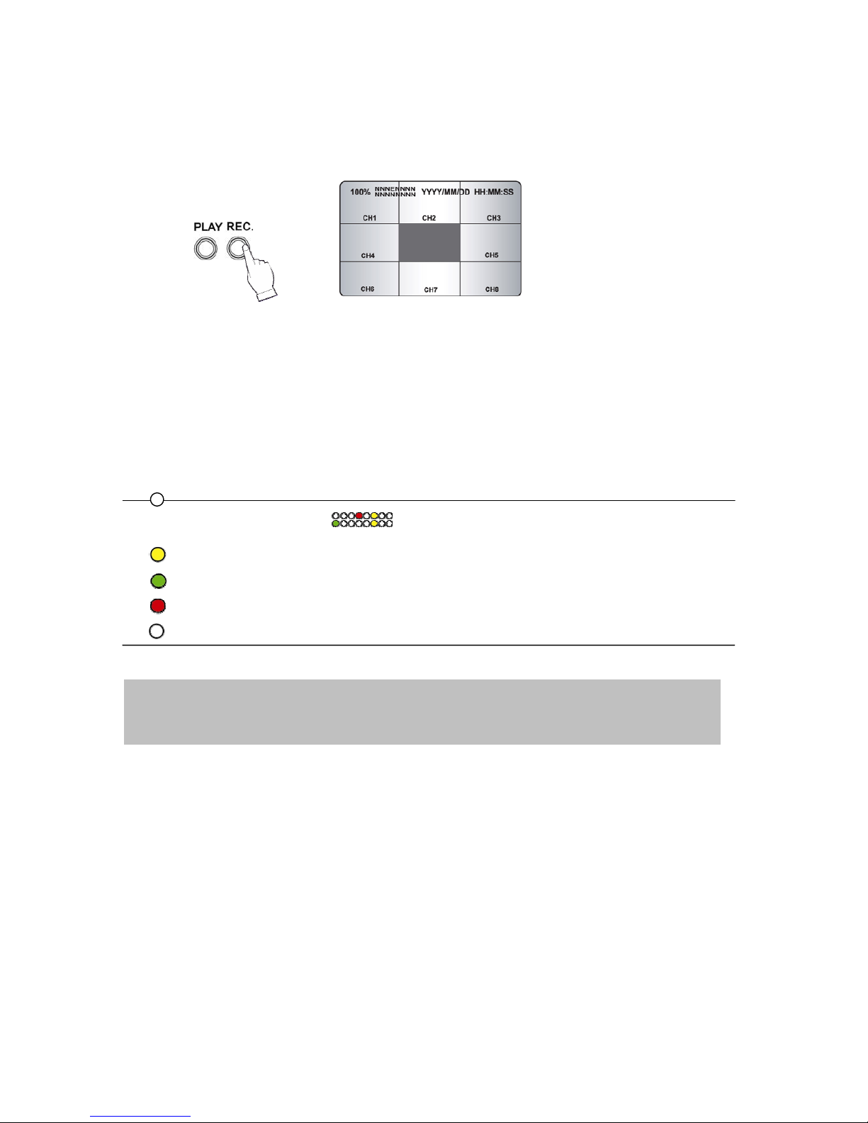
RECORD TYPE SELECTION
Press the REC button and the following message will be displayed as below;
MANUAL MODE
Press the REC button to begin recording.
To stop recording, press the STOP button again.
SCHEDULE MODE
When Schedule mode is selected, the recording will be automatically executed according to the recording
schedule.
The color of record indication ( ) on the screen will be changed according to the type of
recording and refer to the following.
- “ (Yellow) ” : Manual recording status.
- “ (Green) ” : Schedule recording status.
- “ (Red) ” : Event recording status. (Motion detection/ Video loss/ Sensor)
- “ (White) ” : Not recording.
All channels will be displayed by red lights even if an event happened just on one channel.
Red light will be displayed because this unit enters the event record mode when event happened.
If a channel has an event, all channels will be recorded by event recording frame rate to be set in
RECORD PROGRAM menu.
Page 11
-
11
SPECIFICATION
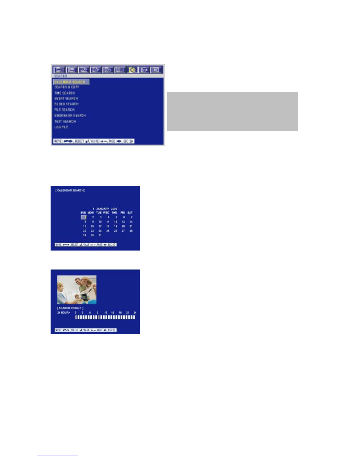
DATA SEARCH & PLAYBACK
Press the T-SRH (Time - search) button, the SEARCH menu screen appears.
TIME SEARCH
CALENDAR SEARCH
At the SEARCH menu;
Press the ENTER button and the CALENDAR SEARCH screen appears.
Select the desired HDD, channel and date using the (-), (+) buttons.
And then press the ENTER button, and the following screen appears.
Move the cursor to the desired position using the , buttons and then press the ENTER button to play the
selected images.
If you press the PLAY button in the real time screen mode,
playback will be executed from the end of the previous
time search and press the desired channel select button.
To exit the playback mode and see the live screen again,
press LV/PB button.
Page 12
-
12
SPECIFICATION
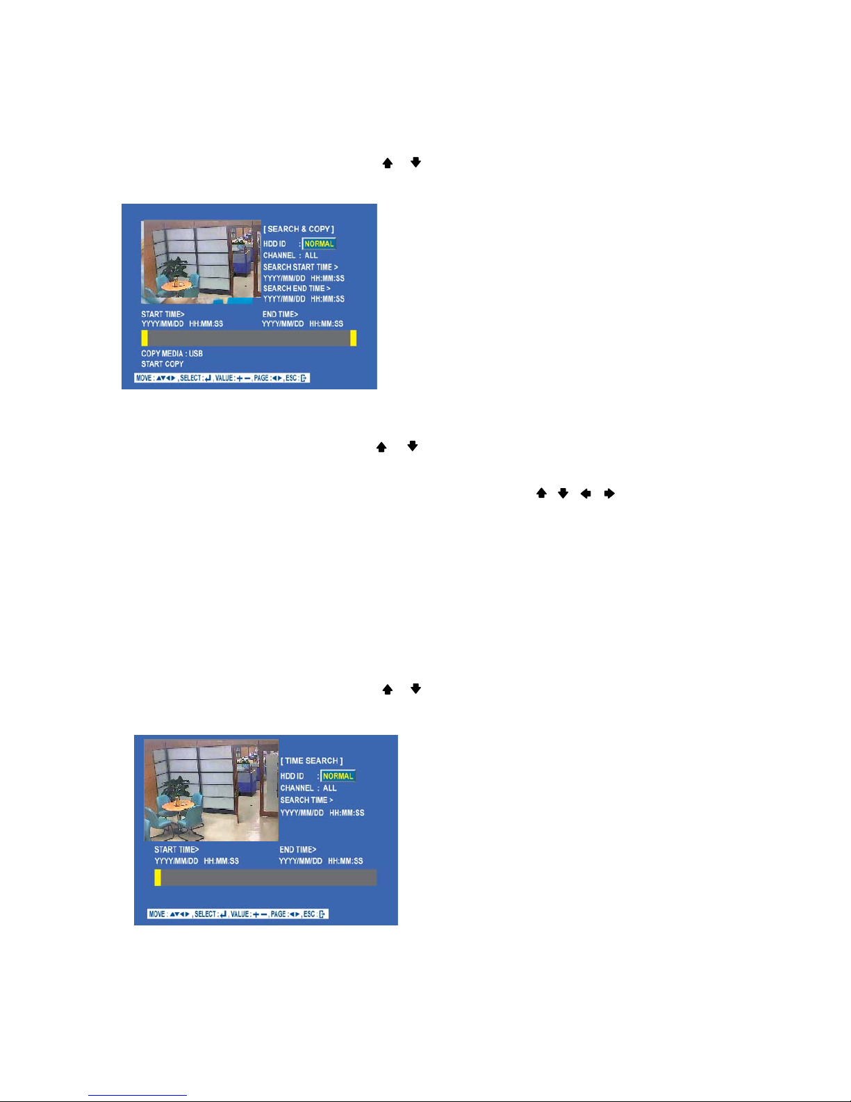
SEARCH & COPY
At the SEARCH menu;
Move the cursor to TIME SEARCH using or button.
Press the ENTER button and TIME SEARCH screen appears.
Select the desired HDD ID using the (-) or (+) button.
Move the cursor to CHANNEL using the or button and select the desired channel using the (-) or (+)
button.
Move the cursor to the desired position of SEARCH TIME using the , , , buttons, and then set up
the desired time using the(-), (+) buttons or turn the JOG DIAL to set the search time.
Press the ENTER button and you can playback.
Move the cursor to START COPY and then press the ENTER button to copy.
Press the ESC button to exit this menu.
TIME SEARCH
At the SEARCH menu;
Move the cursor to TIME SEARCH using or button.
Press the ENTER button and TIME SEARCH screen appears.
Page 13
-
13
SPECIFICATION
Select the desired HDD ID using the (-) or (+) button.
Move the cursor to CHANNEL using the or button and select the desired channel using the (-) or (+)
button.
Move the cursor to the desired position of SEARCH TIME using the , , , buttons, and then set up
the desired time using the(-), (+) buttons or turn the JOG DIAL to set the search time.
Press the ENTER button and you can playback.
Press the ESC button to exit this menu.
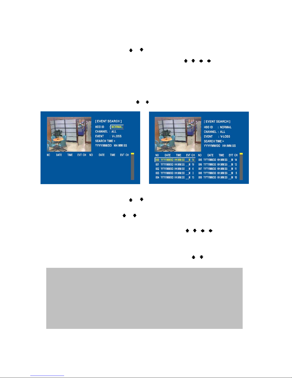
EVENT SEARCH
At the SEARCH menu;
Move the cursor to EVENT SEARCH using or button.
Press the ENTER button and the EVENT SEARCH menu screen appears.
Select the desired HDD ID using the (-) or (+) button.
Move the cursor to CHANNEL using the or button and select the desired channel using the (-) or (+)
button.
Move the cursor to EVENT using the or button and select the event type to search using the (-) or (+)
button.
Move the cursor to the desired position of SEARCH TIME using the , , , buttons, and then set
up the desired time using the(-), (+) buttons.
Press the ENTER button or turn the JOG DIAL, and the event list searched appears.
When the event list appears on the screen, select the desired list using , buttons or JOG DIAL and
press the ENTER button for the playback.
- When video loss is detected, up to five seconds of pre-recording data is stored on the HDD and the details
will be listed in the EVENT LIST. The beep sounds and the LED of the ALARM RESET button will flicker.
Press the ALARM RESET button to remove this signal.
- When the unit receives a signal from the sensor input, DVR begins to record the input data according
to the PRE/POST TIME in the RECORD setup and the details will be listed in the EVENT LIST.
CAUTION
If the internal HDD(s) is initialized, all of the event images will be deleted.
When the unit is in normal recording status, the pre-recording will not be executed.
Page 14
-
14
SPECIFICATION
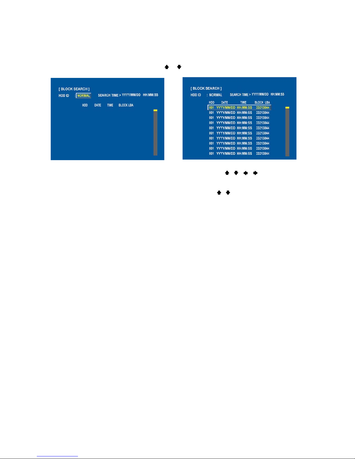
BLOCK SEARCH
At the SEARCH menu;
Move the cursor to BLOCK SEARCH using or button.
Press the ENTER button and the BLOCK SEARCH menu screen appears.
Select the desired HDD ID using the (-) or (+) button.
Move the cursor to the desired position of SEARCH TIME using the , , , buttons, and then set
up the desired time using the(-), (+) buttons. (Or turn the JOG DIAL to search the block list.)
Press the ENTER or turn the JOG DIAL, and the list searched appears.
When the list appears on the screen, select the desired list using , buttons or JOG DIAL and press the
ENTER button for the playback.
Page 15
-
15
SPECIFICATION
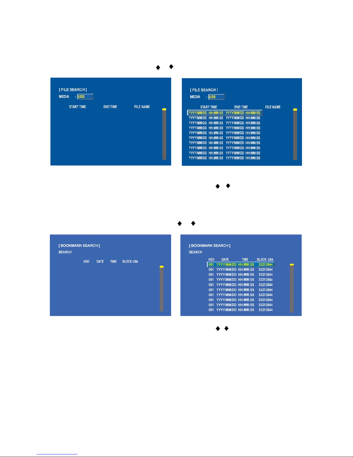
FILE SEARCH
At the SEARCH menu;
Move the cursor to FILE SEARCH using or button.
Press the ENTER button and the FILE SEARCH screen appears.
Select the desired type of MEDIA using the (-) or (+) button.
Press the ENTER button or turn the JOG DIAL, and the list searched appears.
When the list appears on the screen, select the desired list using , buttons or JOG DIAL.
Press the ENTER button for the playback.
BOOKMARK SEARCH
At the SEARCH menu;
Move the cursor to BOOKMARK SEARCH using or button.
Press the ENTER button and the BOOKMARK SEARCH screen appears.
Press the ENTER button, and the list searched appears.
When the list appears on the screen, select the desired list using , buttons or JOG DIAL
Press the ENTER button for the playback.
<How to make Bookmark list>
Press the “PB/PAUSE” button to playback.
Find the desired image using shuttle ring.
Press the “PB/PAUSE” button to see the still picture of the desired image.
Press the “PTZ” button to add the BOOKMARK list.
Page 16
-
16
SPECIFICATION
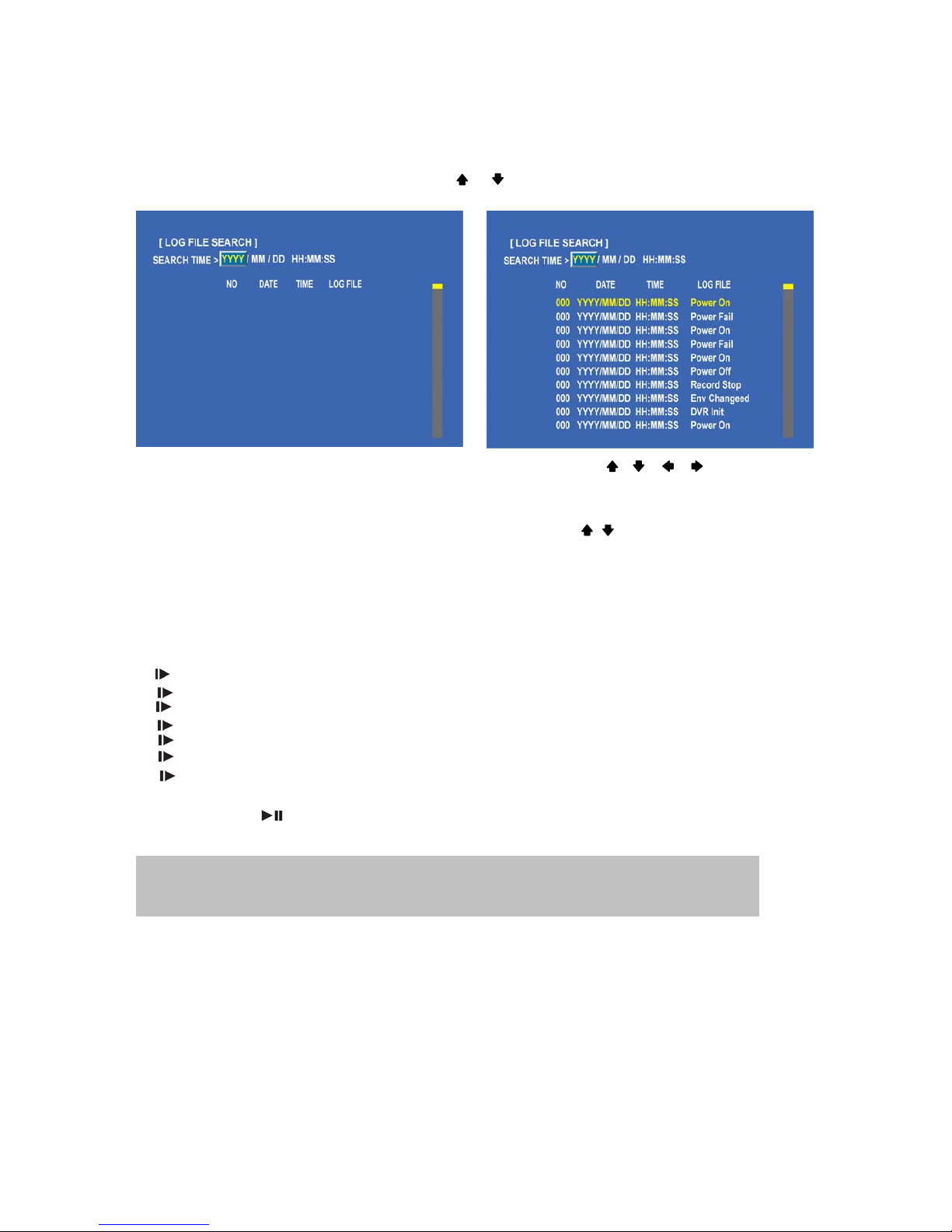
LOG FILE SEARCH
At the SEARCH menu;
Move the cursor to LOG FILE SEARCH using or button.
Press the ENTER button and the LOG FILE SEARCH screen appears.
Move the cursor to the desired position of SEARCH TIME using the , , , buttons, and then set
up the desired time using the(-), (+) buttons.
(Or turn the JOG DIAL to search the desired list.)
Press the ENTER button or turn the JOG DIAL, and the list searched appears.
When the list appears on the screen, select the desired list using , buttons or the JOG DIAL.
SEARCH BUTTON INFORMATION
SLOW ( ( )
Press this button to make the speed level which is slower than normal speed (X1) and displayed it at the upper
left side of screen as below;
(If you press this button again, the playback speed will be changed in the order of the below seven speed level)
i. 1/2 - 2 times slower than normal playback speed
ii. 1/4 - 4 times slower than normal playback speed
iii. 1/8 - 8 times slower than normal playback speed
iv. 1/16 - 16 times slower than normal playback speed
v. 1/32 - 32 times slower than normal playback speed
vi. 1/64 - 64 times slower than normal playback speed
vii. 1/128 - 128 times slower than normal playback speed
PB / PAUSE ( )
Press this button again to pause the playback.
<How to playback a section repeatedly>
Press the “PAUSE” button at the position to start to playback.
And then press the “AUTO” button to set up the A position(starting position).
Press the “PB” button and playback to find the ending position.
Press the “PAUSE” button at the position to end to playback.
And then press the “FREEZE” button to set up the B position(ending position).
Press the “PB” button to playback between A to B repeatedly.
NOTE
If you press the “PB” button to playback, it will playback from the end of played final image.
Page 17

-
17
SPECIFICATION
<How to release the section repetition playback>
Press the “PAUSE” button.
Press the “AUTO” button and then press the “FREEZE” button to exit the section repetition playback mode.
FAST ( X )
Press this button to make faster the speed level which is higher than normal speed (X1) and displayed at the
upper left side of screen as below:
i. 2 - 2 times faster than normal playback speed
ii. 4 - 4 times faster than normal playback speed
iii. 8 - 8 times faster than normal playback speed
iv. 16 - 16 times faster than normal playback speed
v. 32 - 32 times faster than normal playback speed
vi. 64 - 64 times faster than normal playback speed
vii. 128 - 128 times faster than normal playback speed
(However much data may be recorded can be searched in 3 seconds)
DIRECTION (/ / )
Press this button to change direction to forward ( / )or backward ( / ) in playback mode.
Normal Playback Mode
Turn the SHUTTLE ring to the desired playback direction and speed level according to the above drawing
during the playback.
The DVR will go back to the normal playback mode when the SHUTTLE ring is returned to
the center position.
Frame by Frame Playback Mode
Press the PB/PAUSE button to get a still image while the DVR is in the playback mode.
Turn the JOG DIAL in either direction continuously for playback of consecutive frames.
Press the PB/PAUSE button again to return to the previous mode.
Digital Zoom of PTZ camera
Select a pre-set single camera, and then press the PTZ button.
Turn the SHUTTLE RING to zoom in or out.
Using the JOG DIAL in the MENU setup
Turn the JOG DIAL to modify the displayed setup value in MENU setup.
Turn the shuttle ring to set up the “SCHEDULE” in RECORD SETUP of the MENU setup.
NOTE
Press DIR button to make a reversed playback from the end of recorded or
played images during the real time display mode.
NOTE
In the MENU setup, below buttons can be used instead of the JOG DIAL.
: Press this button to modify the setup value.
Page 18
-
18
SPECIFICATION
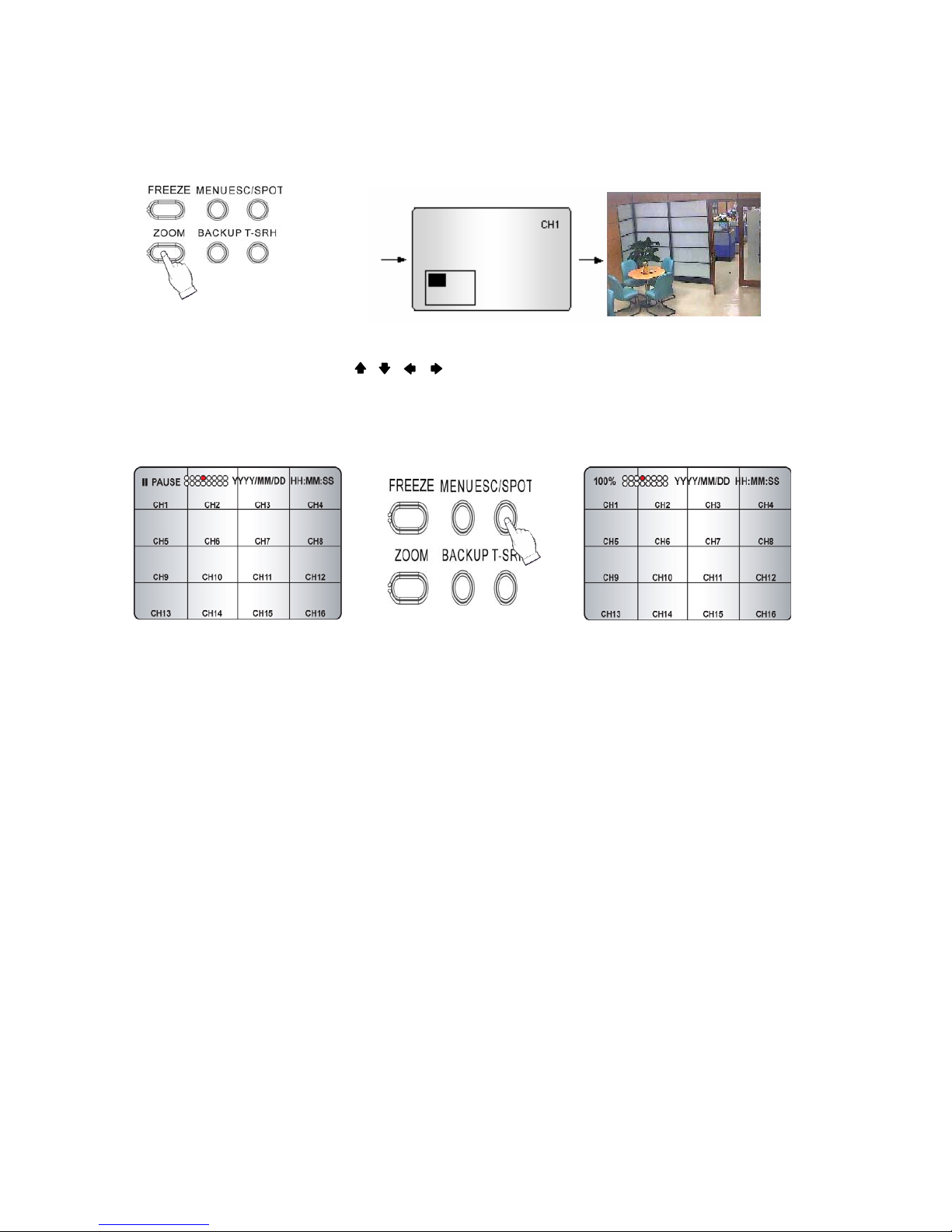
DIGITAL ZOOM
Press the desired camera number button you wish to display on the monitor.
Press the D-ZOOM button. The indication screen appears on the main screen.
Turn JOG DIAL or press the , , , buttons to select the desired location.
Press the ENTER button to change the zoom x2 ~ x4.
Press the ESC button to exit this screen.
SCREEN SELECT (LV/PB)
During the playback, press the LV/PB button to convert the screen into real time display mode. (Press this button
again to return to the playback mode.)
SPOT MONITOR (Call monitor)
Set up the desired mode in “SPOT” of “SCREEN MENU” before executing the SPOT mode.
MANUAL MODE
Press the “SPOT” button on the front panel to toggle “SPOT” mode indicated on the main monitor.
Press a camera button to display that camera on the spot monitor.
OSD of the selected channel will be indicated at the upper left of screen in live mode.
EVENT MODE
Press the “SPOT” button and the Spot monitor will display the channel which an event happened.
SEQUENCE MODE
Press the “SPOT” button and each channel and split channel will be displayed on the Spot monitor in sequence.
►
PLAY CH1
Page 19
-
19
SPECIFICATION
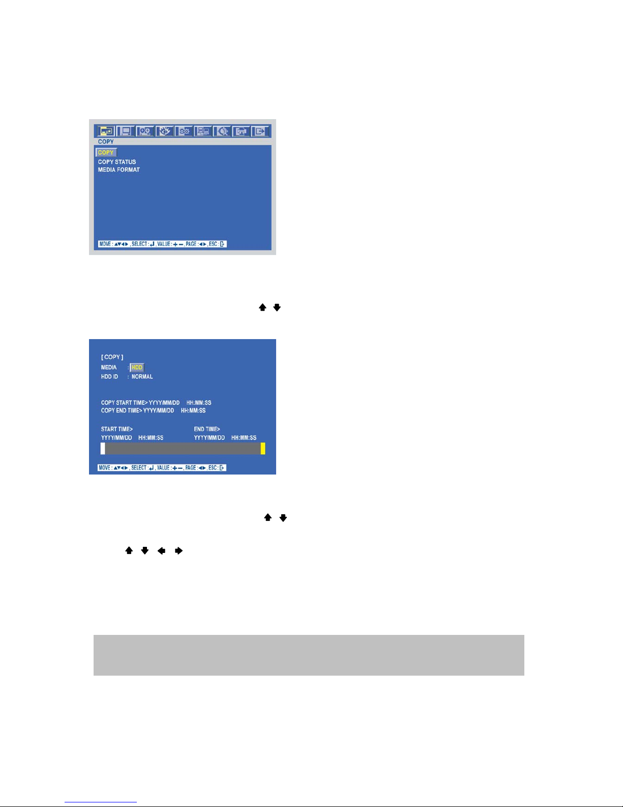
COPY
Press the COPY button to copy the recorded images into other media and the COPY MENU screen appears.
COPY TO HDD
At the COPY menu,
Move the cursor to COPY using the , buttons.
Press the ENTER button and the following screen appears.
Select the desired MEDIA(HDD) (-), (+) buttons or jog dial.
Move the cursor to HDD ID using the , buttons and select the desired HDD to copy among HDD IDs using
the (-), (+) buttons or jog dial.
Move the cursor to the desired position of COPY START TIME/ COPY END TIME using the , , ,
buttons and press the (-) or (+) button to set up the time to set up the COPY START TIME and COPY END
TIME.
** Scroll bar: - Turn the shuttle ring to the right to move the cursor of COPY END TIME or to the left to move
the cursor of COPY START TIME and the cursor will be yellow. And then turn the Jog dial to move
the cursor to the desired time.
- It can operate with just Mouse click.
Press the ENTER button to copy.
NOTE
When the copy is in process, the copying status (ex. “COPY 30%”) will be displayed on the right side of
the monitor. You can search and playback the copied images in HDD with DVR itself
Page 20
-
20
SPECIFICATION
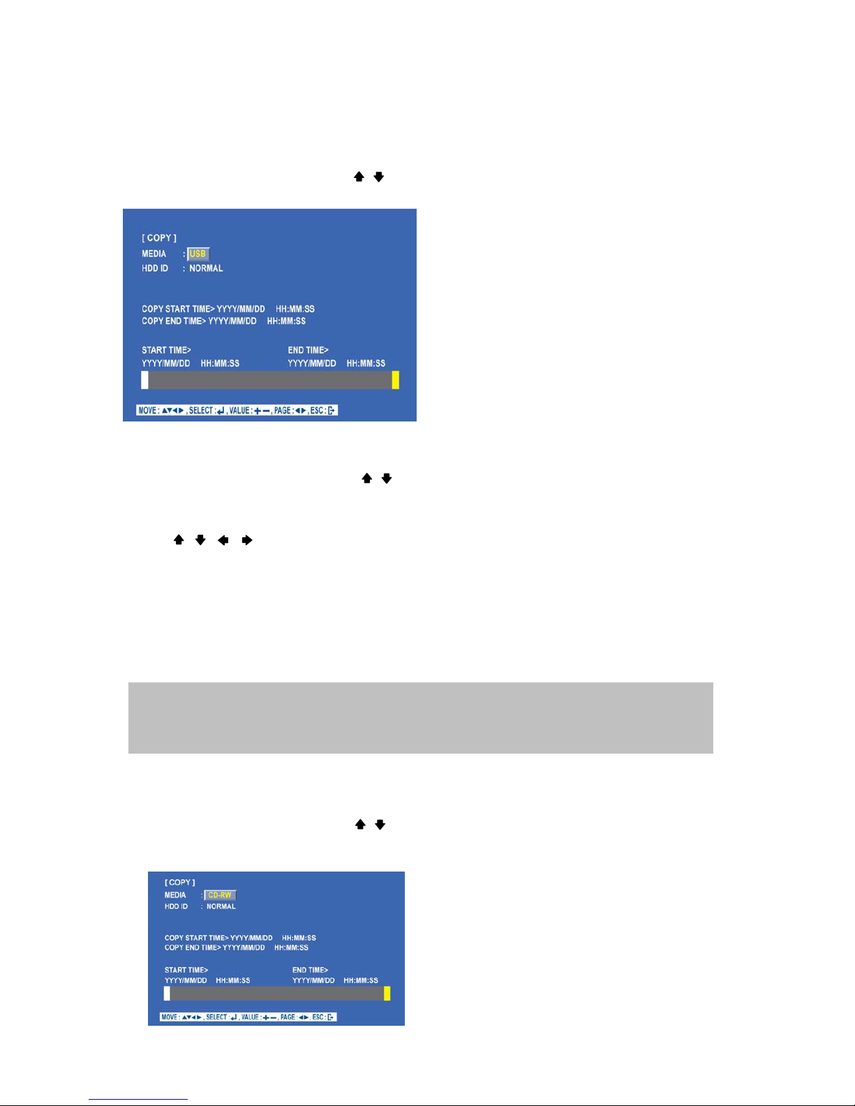
COPY TO USB memory stick
At the COPY menu,
Move the cursor to COPY using the , buttons.
Press the ENTER button and the following screen appears.
Select the desired MEDIA(USB) (-), (+) buttons or jog dial.
Move the cursor to HDD ID using the , buttons and select the desired HDD to copy among HDD IDs using
the (-), (+) buttons or jog dial.
Move the cursor to the desired position of COPY START TIME/ COPY END TIME using
the , , , buttons and press the (-) or (+) button to set up the time or turn the JOG DIAL to set up the
COPY START TIME and COPY END TIME.
** Scroll bar: - Turn the shuttle ring to the right to move the cursor of COPY END TIME or to the left to move
the cursor of COPY START TIME and the cursor will be yellow. And then turn the Jog dial to move
the cursor to the desired time.
- It can operate with just Mouse click.
Press the ENTER button to copy.
COPY TO CD-RW/ DVD±RW
At the COPY menu,
Move the cursor to COPY using the , buttons.
Press the ENTER button and the following screen appears.
When the copy is in process, the copying status (ex. “COPY 30%”) will be displayed on the right side
of the monitor.
You can search and playback the copied images in USB stick memory with DVR itself as well as PC.
Page 21
-
21
SPECIFICATION
Select the desired MEDIA(CD-RW/DVD±RW) (-), (+) buttons or jog dial.
Move the cursor to HDD ID using the , buttons and select the desired HDD to copy among HDD IDs using
the (-), (+) buttons or jog dial.
Move the cursor to the desired position of COPY START TIME/ COPY END TIME using
the , , , buttons and press the (-) or (+) button to set up the time or turn the JOG DIAL to set up the
COPY START TIME and COPY END TIME.
** Scroll bar: - Turn the shuttle ring to the right to move the cursor of COPY END TIME or to the left to move
the cursor of COPY START TIME and the cursor will be yellow. And then turn the Jog dial to move
the cursor to the desired time.
- It can operate with just Mouse click.
Press the ENTER button to copy.
When the copy is done, the CD-RW or DVD±RW tray will be opened automatically.
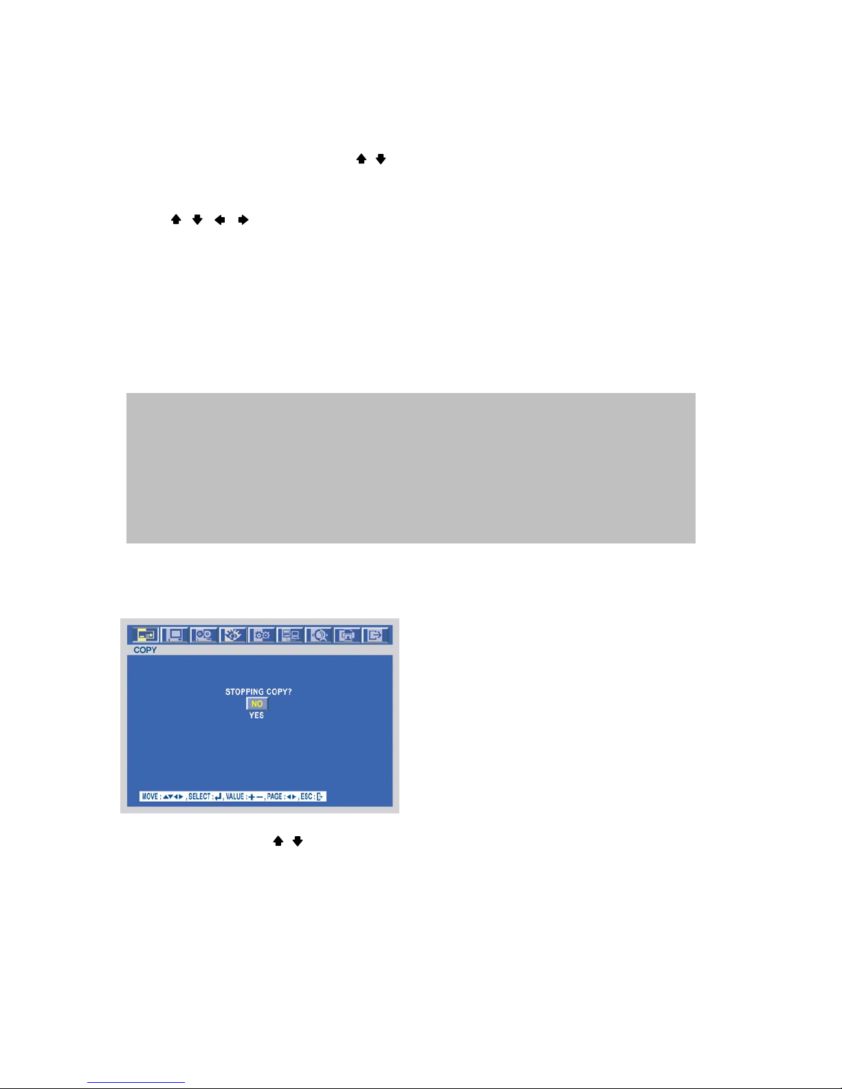
STOPPING COPY
Press the COPY button to stop copying and the following screen appears.
Move the cursor using the , buttons and select “YES” or “NO” and then press the ENTER button.
When the copy is in process, the copying status(ex. “COPY 30%”) will be displayed on the right side
of the monitor.
NOTE
- CD-RW or DVD±RW is option and this DVR need the interface board to install a built-in CD-RW
or DVD±RW.
- If you want a built-in CD-RW or DVD±RW, must purchase it from a authorized dealer.
- You can search and playback the copied images in CD or DVD with DVR itself as well as PC.
Page 22
-
22
SPECIFICATION
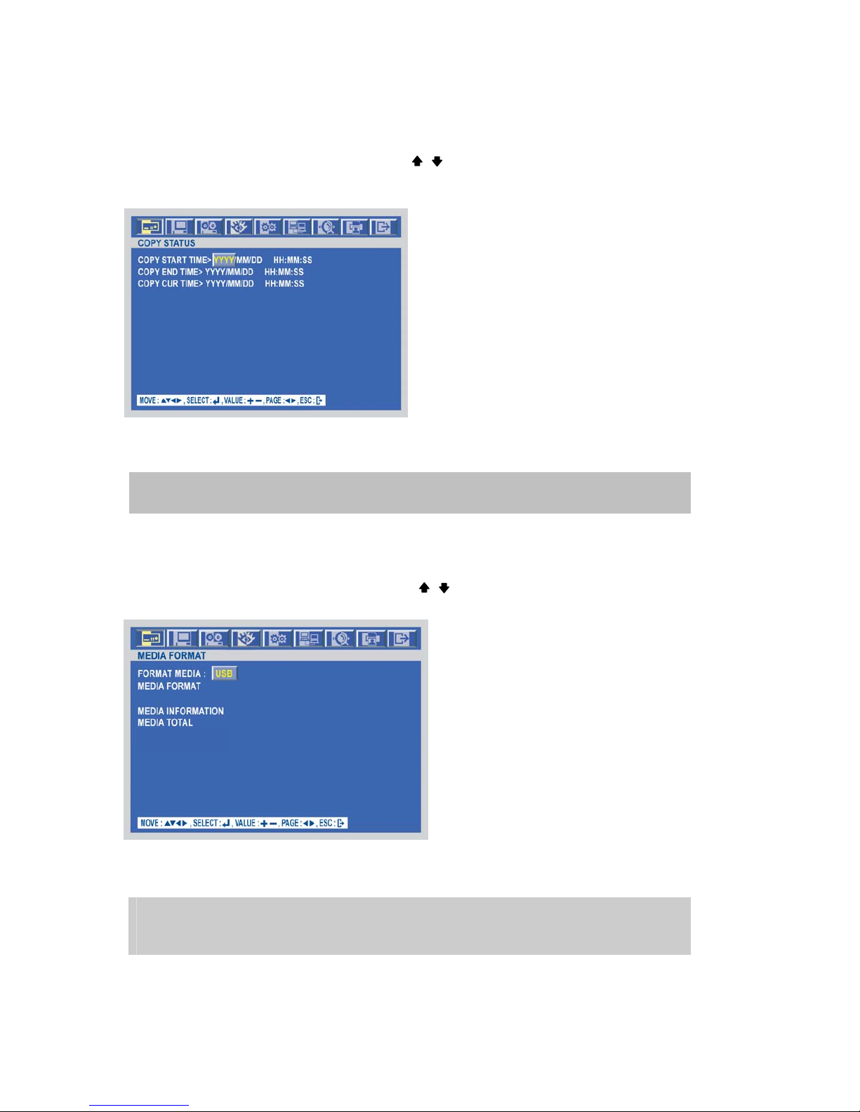
COPY STATUS
At the COPY menu,
Move the cursor to COPY STATUS using the , buttons.
Press the ENTER button to see the current copying status and the following screen appears.
Press the ESC button to exit this menu.
MEDIA FORMAT
At the COPY menu,
Move the cursor to MEDIA FORMAT using the , buttons.
Press the ENTER button and the following screen appears.
Select formatting media using the (-), (+) button.
Move the cursor to MEDIA FORMAT and then press the “ENTER” button.
The message, “FORMATTING” will be displayed while formatting.
NOTE
If you don’t connect any media, you can see the message, “Fail”.
CUR TIME : Indicate current copying situation among the total copying data.
Page 23
-
23
SPECIFICATION
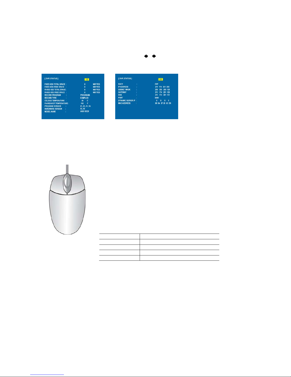
DVR STATUS
Press the “ENTER” button or double-click the left button of Mouse, The SYSTEM INFOMATION screen will
appear. To see the next page, press the , or use the wheel scroll of Mouse.
Press the STATUS button again to move on next information screen or press the “ESC” button
to exit the menu.
MOUSE CONTROL
* Double-click the left button on the mouse to select menu item.
○1 Status display Double-click of the left button
○3 Menu display One-click of the right button
○3 Exit Double-click of the right button
○2 Value change Turning the wheel scroll
○1 Select Double-click on the item or icon
○1
○
2
○
3
Page 24
-
24
SPECIFICATION
MENU setup
Press the MENU button for the desired DVR setting.
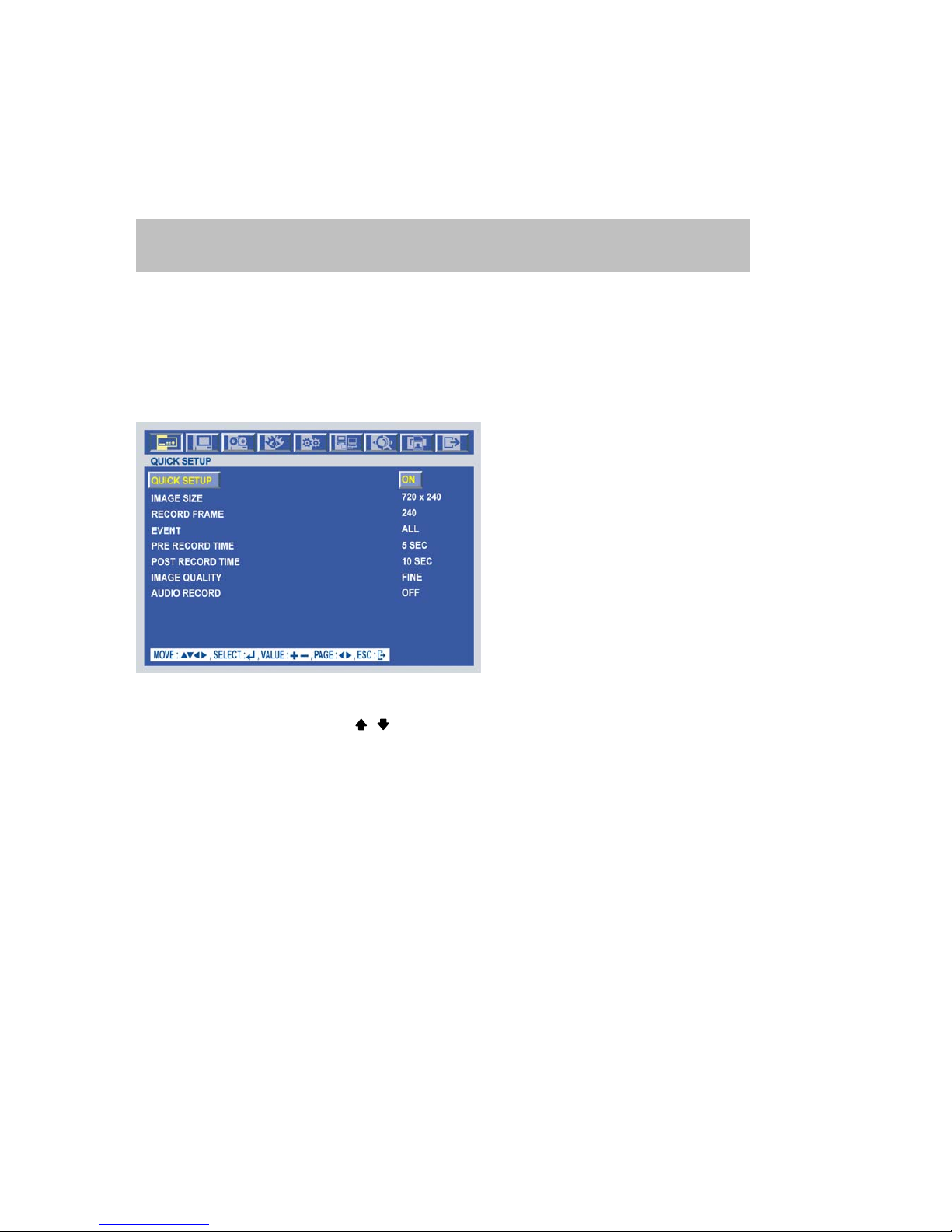
QUICK SETUP
Press the MENU button and the QUICK SETUP menu appears as the following picture.
** This menu is simply used when user want to change just a few important settings.
Select the desired item using the , buttons and set up the value using the (-), (+) buttons or jog dial.
QUICK SETUP
Select “ON” or “OFF” using the (-), (+) buttons or jog dial to use the QUICK SETUP setting.
IMAGE SIZE
Select the desired IMAGE SIZE for recording using the (-), (+) buttons or jog dial.
RECORD FRAME
Select the desired frame rate for normal recording using the (-), (+) buttons or jog dial.
All event channels will be recorded by the setting RECORD FRAME/16.
For example, if you set RECORD FRAME to 100, 16 each channel will be recorded by 6 ips.
You can use the mouse instead of buttons on the front panel of DVR.
Simply click the desired icon or item in case of using the mouse.
Page 25
-
25
SPECIFICATION
EVENT
Select a kind of EVENT using the (-), (+) buttons or jog dial.
If you want to select all kind of event, choose “ALL” and if you don’t want event recording,
choose “OFF”.
The default is “ALL”.
PRE RECORD TIME
Select the desired time for pre-recording using the (-), (+) buttons or jog dial.
When video loss, alarm or motion is detected, the DVR will store pre-recorded data during the selected time.
The pre-recording time can be set from 0 second to 5 second and the default is “5”.
POST RECORD TIME
Select the desired time for post-recording using the (-), (+) buttons or jog dial.
When video loss, alarm or motion is detected, the DVR will store post-recorded data during the selected period.
The post-recording time can be set from 0 second to 60 second and the default is “10”.
IMAGE QUALITY
Select the desired image quality using the (-), (+) buttons or jog dial.
There are 3 kinds of image quality.
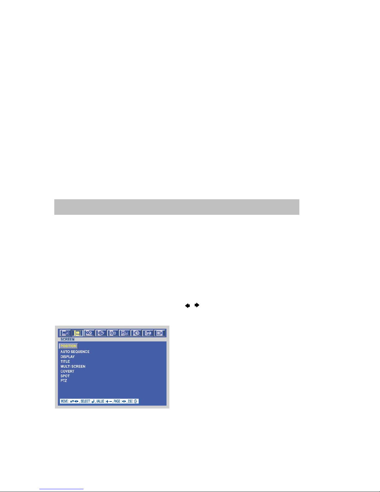
SCREEN
To set up the SCREEN menu,
Move the cursor to the SCREEN icon using the , buttons in the MENU screen.
Press the ENTER button when the cursor is on the SCREEN icon and the following items appear.
NOTE: The pre- and post- recording is not valid in normal recording mode.
Page 26
-
26
SPECIFICATION
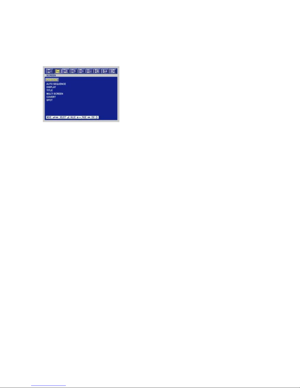
POSITION
At the SCREEN menu,
Press the ENTER button when the cursor is on the POSITION and the following items appear.
Change the value of the HORIZONTAL POSITION using the (-), (+) buttons or jog dial to adjust the horizontal
position of the screen.
* The value is from -4 to +4 and the default is “0”.
Change the value of the VERTICAL POSITION using the (-), (+) buttons or jog dial to adjust the vertical
position of the screen.
* The value is from -4 to +4 and the default is “0”.
To exit this POSITION menu, press the ESC button.
At the SCREEN menu
Press the ENTER button when the cursor is on the POSITION and the following items appear.
Change the value of the HORIZONTAL POSITION using the (-), (+) buttons or jog dial to adjust
the horizontal position of the screen.
* The value is from -4 to +4 and the default is “0”.
Change the value of the VERTICAL POSITION using the (-), (+) buttons or jog dial to adjust the
vertical position of the screen.
* The value is from -4 to +4 and the default is “0”.
To exit this POSITION menu, press the ESC button.
Page 27
-
27
SPECIFICATION
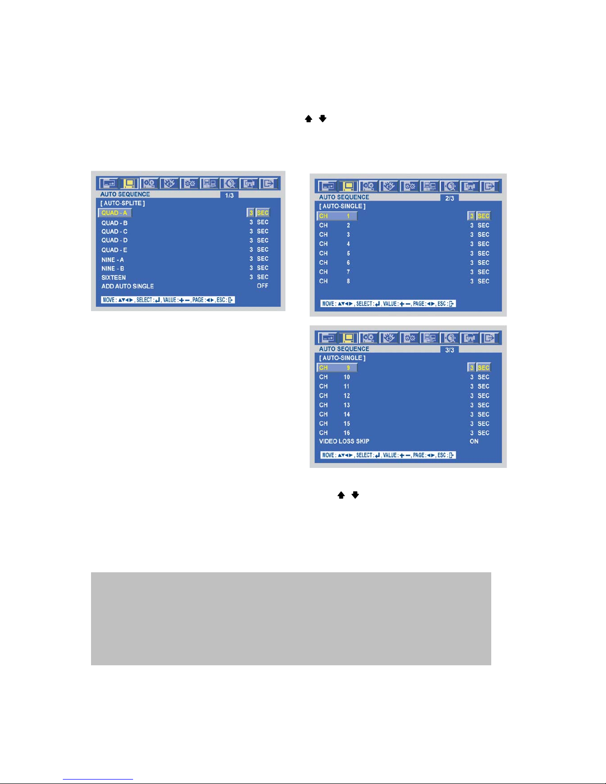
AUTO SEQUENCE
At the SCREEN menu,
Move the cursor to the AUTO SEQUENCE using , buttons.
Press the ENTER button when the cursor is on the AUTO SEQUENCE and the following 3 pages screen
appears.
Move the cursor to each single or split channel using the , buttons.
- When the desired channel is selected, change the value of AUTO SEQUENCE duration using the (-), (+)
buttons or jog dial to set the length of time for switching each channel in sequence.
* The value is from 1SEC to 60SEC and the default is “3SEC”.
To exit this AUTO SEQUENCE menu, press the ESC button.
VIDEO LOSS SKIP :
If selected ON, every VIDEO LOSS channel will be skipped in the AUTO SEQUENCE mode.
The default is “ON”.
ADD AUTO SINGLE:
If selected OFF, every single channel will be skipped in the AUTO SEQUENCE mode.
The default is “OFF”.
Page 28
-
28
SPECIFICATION
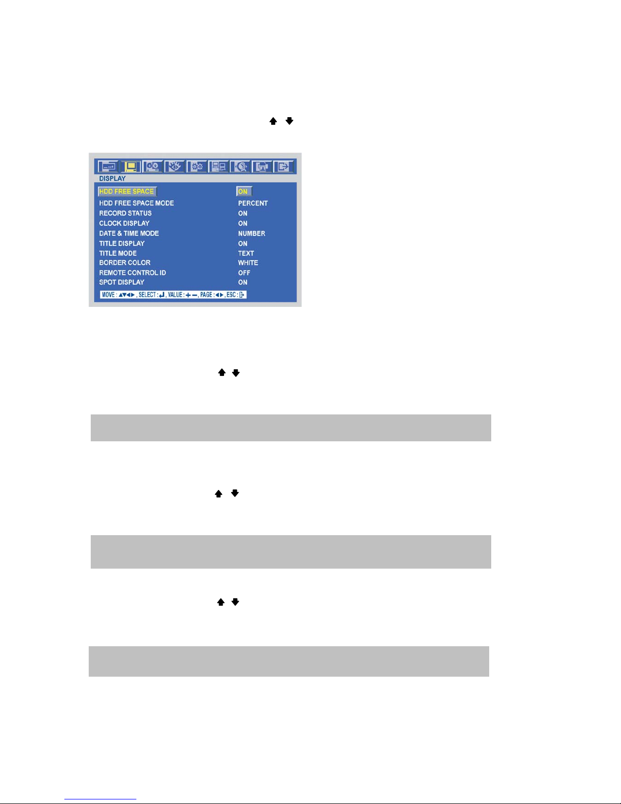
DISPLAY
At the SCREEN menu,
Move the cursor to the DISPLAY using , buttons.
Press the ENTER button when the cursor is on the DISPLAY and the following items appear.
To exit this DISPLAY menu, press the ESC button.
HDD FREE SPACE
At the DISPLAY menu,
Move the cursor using the , buttons to select the HDD FREE SPACE.
Use the (-), (+) buttons or jog dial to choose “ON” or “OFF”.
* The default is “ON”.
HDD FREE SPACE MODE
At the DISPLAY menu,
Move the cursor using the , buttons to select the HDD FREE SPACE MODE.
Use the (-), (+) buttons or jog dial to choose “PERCENT” or “GIGABYTE”.
* The default is “PERCENT”.
RECORD STATUS
At the DISPLAY menu,
Move the cursor using the , buttons to select the RECORD STATUS.
Use the (-), (+) buttons or jog dial to choose “ON” or “OFF”.
* The default is “ON”.
ON: Remaining capacity of the fixed(not backup) HDDs will be displayed on the screen.
PERCENT: Remaining capacity of the fixed HDDs will be displayed on the screen in percent.
GIGABYTE: Remaining capacity of the fixed HDDs will be displayed on the screen in gigabyte.
ON: Displaying the recording status of each channel on the screen.
Page 29

-
29
SPECIFICATION
CLOCK DISPLAY
At the DISPLAY menu,
Move the cursor using the , buttons to select the CLOCK DISPLAY.
Use the (-), (+) buttons or jog dial to choose “ON” or “OFF”.
* The default is “ON”.
DATE&TIME MODE
At the DISPLAY menu,
Move the cursor using the , buttons to select the DATE&TIME MODE.
Use the (-), (+) buttons or jog dial to choose “NUMBER” or “INITIAL”.
* The default is “NUMBER”.
TITLE DISPLAY
At the DISPLAY menu, Move the cursor using the , buttons to select the TITLE DISPLAY.
Use the (-), (+) buttons or jog dial to choose “ON” or “OFF”.
* The default is “ ON”.
TITLE MODE
At the DISPLAY menu, Move the cursor using the , buttons to select the TITLE MODE.
Use the (-), (+) buttons or jog dial to choose “TEXT” or “BITMAP”.
* The default is “ TEXT”.
BORDER COLOR
At the DISPLAY menu,
Move the cursor using the , buttons to select the BORDER COLOR.
Use the (-), (+) buttons or jog dial to choose “WHITE” or “BLACK”.
* The default is “WHITE”.
ON: The date and time will be displayed on the screen.
NUMBER: All date and time will be displayed in numbers.
Ex. 2005/01/01 00:00:00
INITIAL : the month section will be displayed in character.
Ex. JAN. 01 2005 00:00:00
ON: Each channel title will be displayed on the screen.
WHITE: The color of the border line will be displayed on the multi-channel screen in white.
BLACK: The color of the border line will be displayed on the multi-channel screen in black.
A bitmap is a type of graphics file on a computer.
Page 30
-
30
SPECIFICATION
REMOTE CONTROL ID
At the DISPLAY menu,
Move the cursor using the , buttons to select the REMOTE CONTROL ID.
Use the (-), (+) buttons or jog dial to choose “ON” or “OFF”.
* The default is “OFF”.
SPOT DISPLAY
At the DISPLAY menu,
Move the cursor using the , buttons to select the SPOT DISPLAY.
Use the (-), (+) buttons or jog dial to choose “ON” or “OFF”.
* The default is “OFF”.
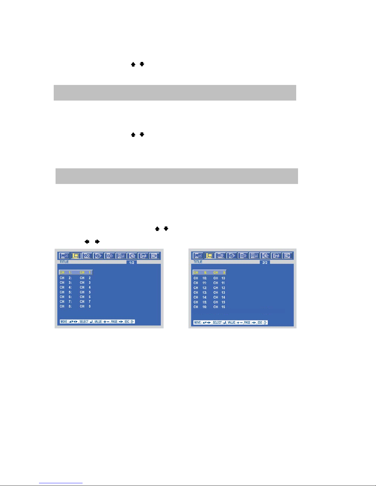
TITLE
At the SCREEN menu,
Move the cursor to the TITLE using , buttons.
Press the ENTER button when the cursor is on the TITLE and the following 2 pages screen appears.
Use the , buttons to see the next page.
ON: The remote controller ID will be displayed on the screen.
ON: Each channel title will be displayed on the spot monitor screen.
Page 31
-
31
SPECIFICATION
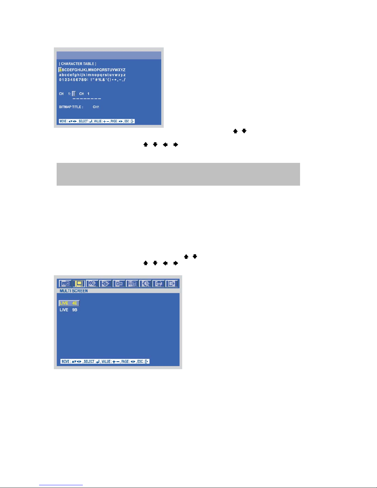
Press the ENTER button after selecting desired channel using the , buttons and the following screen
appears.
Select the character using the , , , buttons and then press the ENTER button.
To exit this CHARACTER TABLE screen, press the ESC button.
MULTI-SCREEN
You can select the desired channels and make a 4 split screen and a 9 split screen using this menu.
At the SCREEN menu,
Move the cursor to the MULTI SCREEN using , buttons.
Select the character using the , , , buttons and then press the ENTER button.
Press the ENTER button when the cursor is on the MULTI SCREEN and the following screen appears.
To exit this MULTI SCREEN menu, press the ESC button.
CHANNEL TITLE MODE: There are “TEXT” and “BITMAP”.
TEXT: Using the CHARACTER TABLE
BITMAP: It is possible to download new characters using the software if you want.
Page 32
-
32
SPECIFICATION
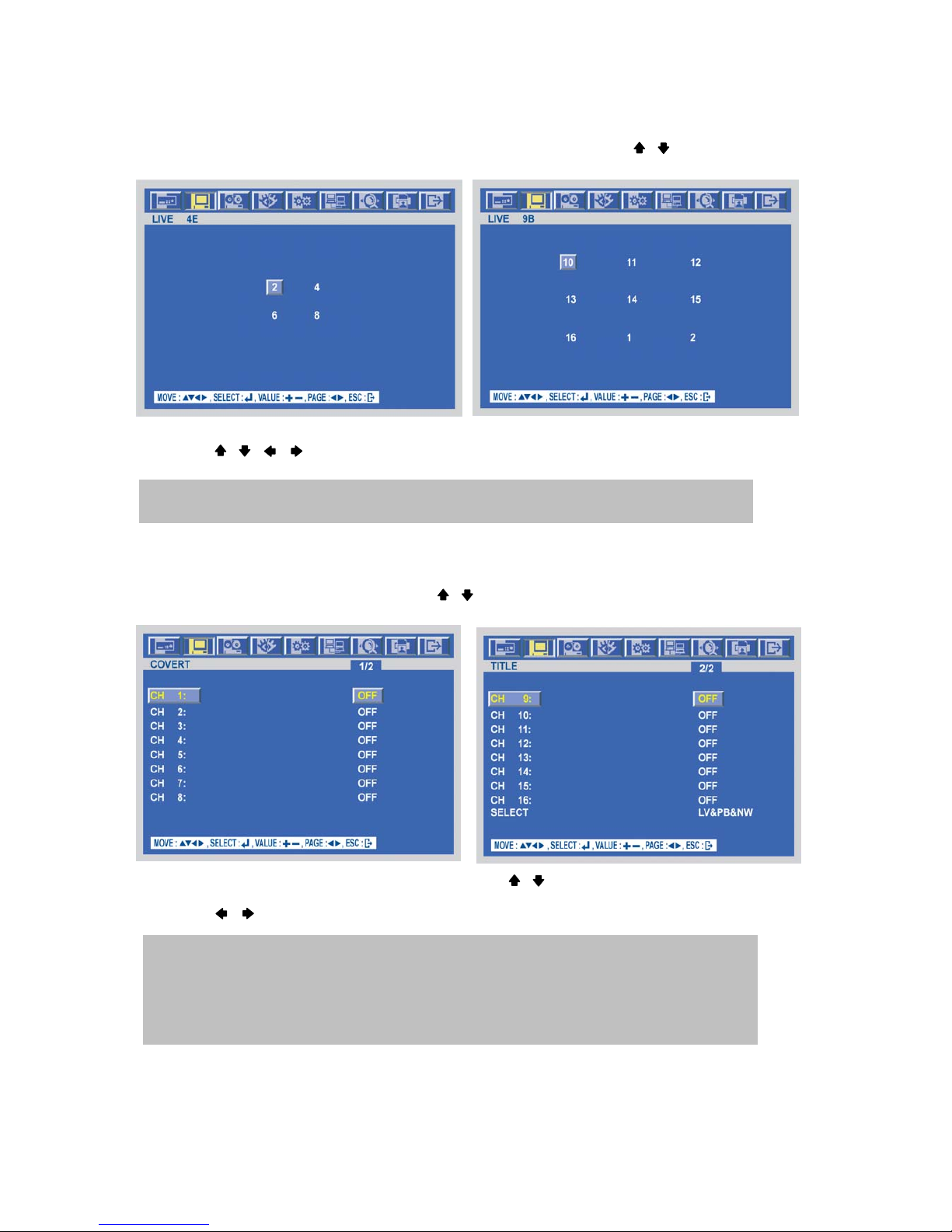
LIVE 4E / LIVE 9B
Press the ENTER button after selecting “LIVE 4E” or “LIVE 9B” using the , buttons.
[LIVE4E] [LIVE9B]
Set the desired number of camera in each channel screen using the (-), (+) buttons or jog dial.
Use the , , , buttons to set the other channel screen.
To exit this screen, press the ESC button.
COVERT
At the SCREEN menu,
Move the cursor to the COVERT using the , buttons.
Press the ENTER button when the cursor is on the COVERT and the following 2 pages screen appears.
Move the cursor and select the desired item using the , buttons.
Use the (-), (+) buttons or jog dial to choose “ON” or “OFF”.
Use the , buttons to see the next page.
In the each of LIVE4E and LIVE9B, same camera numbers should not be selected.
ON: Selected channel will be displayed in black screen (Hidden camera).
SELECT: It is possible to select among “LIVE&PLAYBACK&NETWORK”, “PLAYBACK&NETWORK”,
“LIVE&NETWORK”, “LIVE&PLAYBACK”, “NETWORK”, “PLAYBACK” and “LIVE”.
- LIVE: To covert selected channels on live screen
- PLAY: To covert selected channels on playback screen
- NETWORK: To covert selected channels on network viewer screen
Page 33
-
33
SPECIFICATION
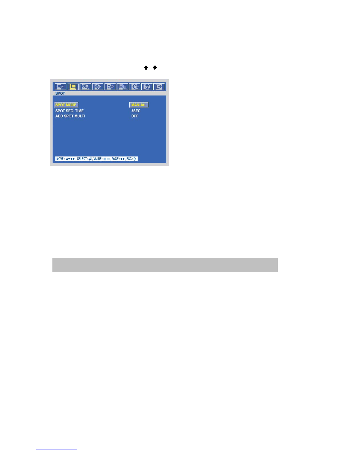
SPOT
At the SCREEN menu,
Move the cursor to the SPOT using , buttons.
Press the ENTER button when the cursor is on the SPOT and the following screen appears.
To exit this SPOT menu, press the ESC button.
SPOT MODE
Use the (-), (+) buttons or jog dial to select the SPOT MODE.
- MANUAL: Manually select the channel of spot monitor.
- EVENT: Event channel will be displayed automatically on spot monitor.
- SEQUENCE: Every single channel will be switching and displaying in sequence.
SPOT SEQ. TIME
Use the (-), (+) buttons or jog dial to set the SPOT SEQ. TIME.
The duration of spot sequence can be set from 1SEC to 60SEC.
ADD SPOT MULTI
Use the (-), (+) buttons or jog dial to set the ADD SPOT MULTI.
You can see the multi-channel screen on spot monitor if you set “ON”.
It is possible to support OSD and not to roll off because of digital spot.
Page 34
-
34
SPECIFICATION
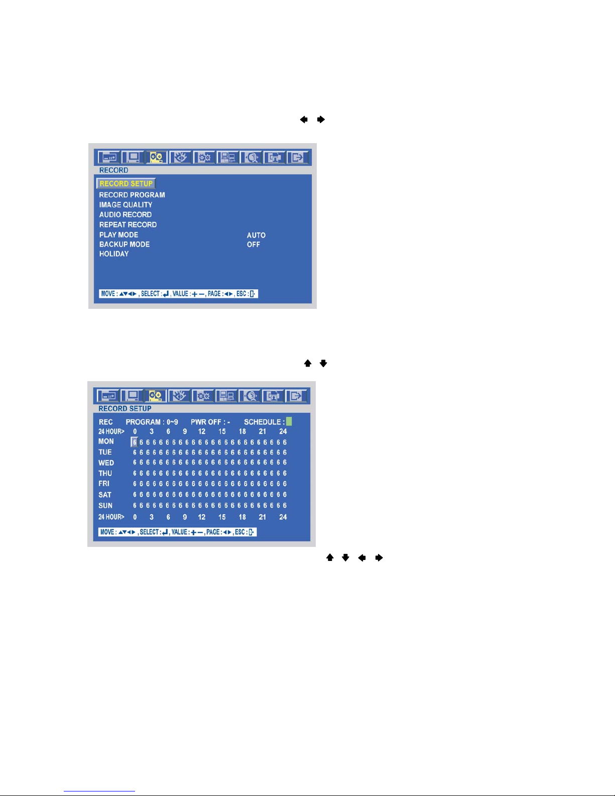
RECORD
To set up the RECORD menu,
Move the cursor to the RECORD icon using the , in the MENU screen.
Press the ENTER button when the cursor is on the RECORD icon and the following items appear.
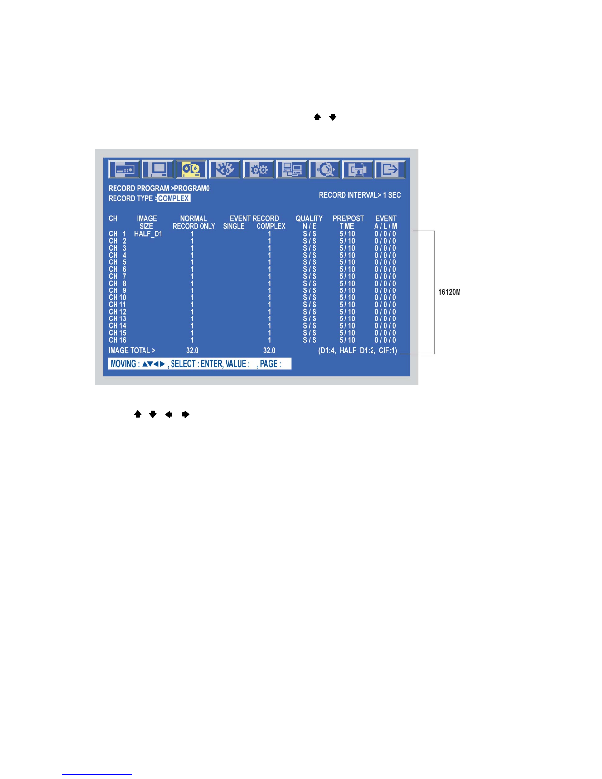
RECORD SETUP
At the RECORD menu,
Move the cursor to the RECORD SETUP using , buttons.
Press the ENTER button when the cursor is on the RECORD SETUP and the following screen appears.
Move the cursor to choose the desired time using the , , , buttons.
Select the desired program among PROGRAM 0~9 and POWER OFF using the (-), (+) buttons or jog dial.
Turn right the shuttle ring to set up the schedule of programmed time and the program number will be green.
Turn the left the shuttle ring to release the schedule mode.
Or move the cursor to the desired position and then click the green square next to “SCHEDULE” using the
Mouse.
Press the ESC button to exit this RECORD SETUP menu or press the ENTER button to enter the RECORD
PROGRAM menu.
Page 35
-
35
SPECIFICATION
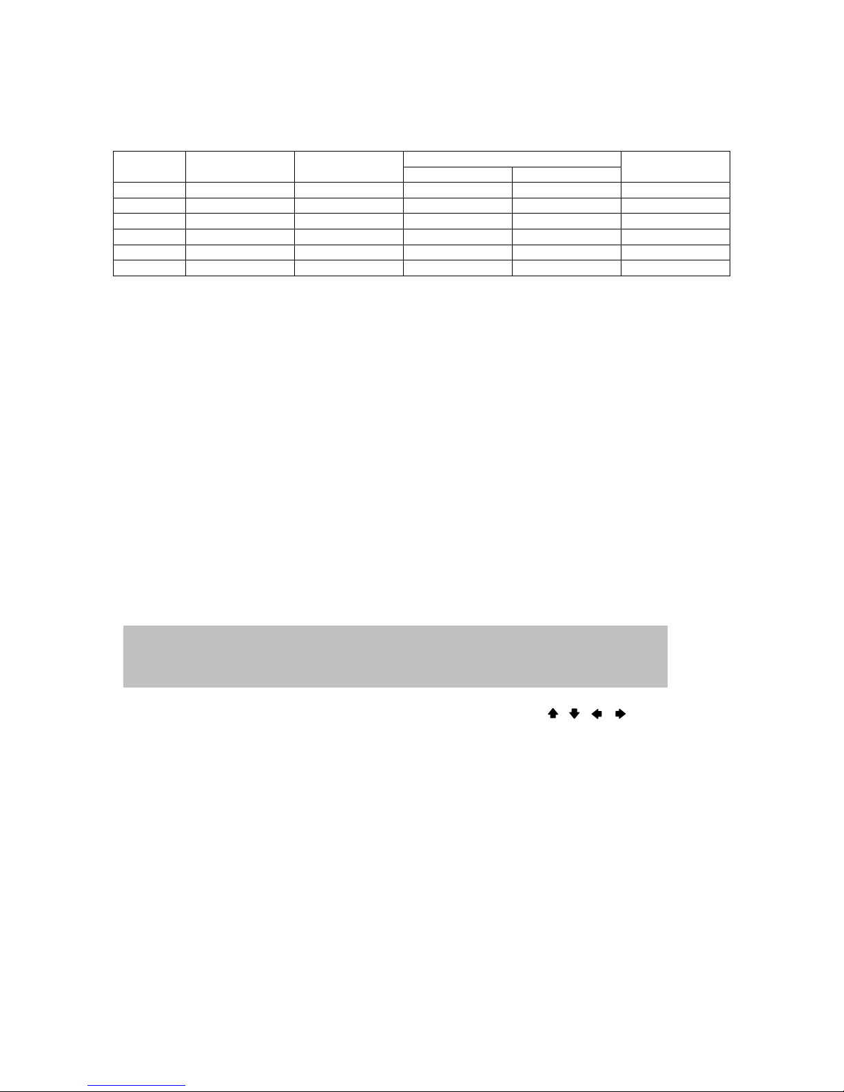
RECORD PROGRAM
At the RECORD menu,
Move the cursor to the RECORD PROGRAM using , buttons.
Press the ENTER button when the cursor is on the RECORD PROGRAM and the following screen appears.
Use the , , , buttons to move the cursor to the desired item.
Select the desired RECORD TYPE using the (-), (+) buttons or jog dial.
- SINGLE : Only one event channel will be recorded by setting event recording frame rate and the other
channels will be recorded by rest event recording fps/N(channel number) when an event happened.
For example, if you connect 16 cameras and set EVENT RECORD of all channels to “30”, one event
channel will be recorded by 30 ips and the other channel will be recorded by 90(Max. 120 – 30)/15 =
6 ips.
You can set the more recording frame rate for one channel.
(This type is good for the place where the event is rarely happened.)
- COMPLEX : All event channels will be recorded by max. event recording frame rate/N(channel number)
when the event happened.
For example, if you connect 16 cameras and set EVENT RECORD of all channels to Max. frame
rate, 100, 16 each channel will be recorded by 100/N = 6 ips.
(This type is good for the place where the event is often happened.)
Page 36
-
36
SPECIFICATION
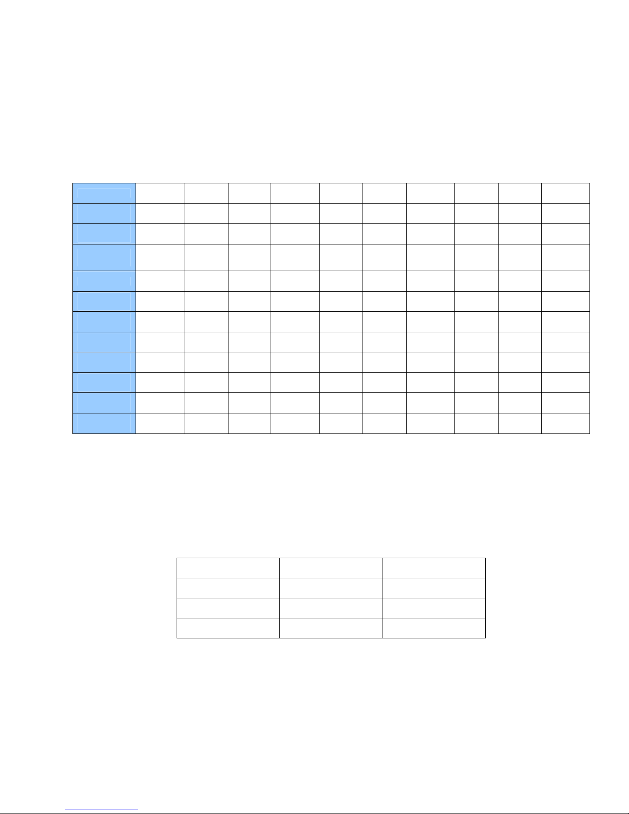
< Result table of total frame rate >
Event Record
Record
Type
Image Size Normal Record
Event Channel Other Channel
Unit
Single 360 x 240 Normal Frame ES_Frame RS_Frame CIF/1 SEC
720 x 240 Normal Frame ES_Frame RS_Frame CIF/1 SEC
720 x 480 Normal Frame ES_Frame RS_Frame CIF/1 SEC
Complex 360 x 240 Normal Frame EC_Frame EC_Frame CIF/1 SEC
720 x 240 Normal Frame EC_Frame EC_Frame CIF/1 SEC
720 x 480 Normal Frame EC_Frame EC_Frame CIF/1 SEC
- ES_Frame : Event single frame rate.
- EC_Frame : Event complex frame rate.
- RS_Frame : Remain single frame rate = ( Max. Frame Rate – ES_Frame) / 15.
RECORDING INTERVAL is fixed at 1 SEC (Second).
This means each channel will record by setting frame rate per SEC.
Set the IMAGE SIZE of each channel using the (-), (+) buttons or jog dial. There are the 3 types of
720x480(D
1
), 720x240(Half-D1) and 360x240(CIF).
* The default is 720x240.
You can set the frame rate of each channel using the (-), (+) buttons or jog dial.
- N : Frame rate for normal recording
- E : Frame rate for event recording
Set the IMAGE QUALITY for normal recording and for event recording of each channel using the (-), (+)
buttons or jog dial.
There are 3 types, Fine(F)/ Superfine(S)/ Low(L).
Set the PRE TIME and POST TIME using the (-), (+) buttons or jog dial. When the event is detected, the DVR
will store pre- and post-recorded data during the selected period.
Choose the type of the EVENT using the (-), (+) buttons or jog dial and , , , buttons if you want the
event recording(Motion detection/ Video loss/ Alarm) or not. “O” means that the event recording is “ON” and ““ means that the event recording is “OFF”.
The value of “PRE TIME” is from 0 to5 seconds and the value of “POST TIME” is from 0 to 60 seconds.
The default of pre-recording time is 5 seconds and post-recording is 10 seconds.
Note: The pre- and post- recording is not valid in normal recording mode.
Page 37
-
37
SPECIFICATION
< PROGRAM DEFAULT>
These are 10 kinds of program and you can change the program setting.
PROGRAM
0 1 2 3 4 5 6 7 8 9
RECORD
TYPE
COMPLEX SINGLE SINGLE COMPLEX SINGLE SINGLE COMPLEX SINGLE SINGLE COMPLEX
RECORDING
INTERVAL
1 1 1 1 1 1 1 1 1 1
IMAGE
SIZE
704x576
704x288
352x288
352x288 352x288 360x240 704x288 704x288 704x288 704x576 704x576 704x576
NORMAL
Max 4 7 7 2 3 3 1 1 1
EVENT
SINGLE
0 15 30 0 15 30 0 15 30 0
EVENT
COMPLEX
Max 0 0 7 0 0 3 0 0 1
QUALITY
NORMAL
F L F S L F S L F S
QUALITY
EVENT
F L F S L F S L F S
PRE-ALARM
RECORDING
5 5 5 5 5 5 5 5 5 5
POST-ALARM
RECORDING
10 10 10 10 10 10 10 10 10 10
EVENT
ON/OFF
V-Loss
ON
V-Loss
ON
V-Loss
ON
V-Loss
ON
V-Loss
ON
V-Loss
ON
V-Loss
ON
V-Loss
ON
V-Loss
ON
V-Loss
ON
Image sizes PAL (UK) NTSC (USA)
D1 704 x 576 720 x 480
2CIF 704 x 288 720 x 240
CIF 352 x 288 360 x 240
Page 38
-
38
SPECIFICATION
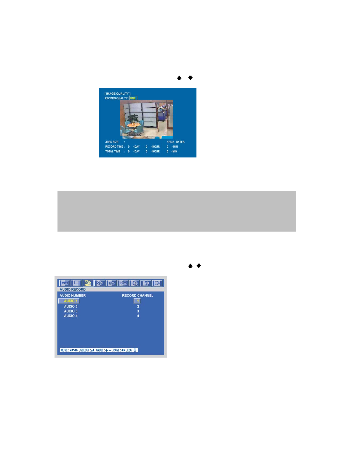
IMAGE QUALITY
At the RECORD menu,
Move the cursor to the IMAGE QUALITY using , buttons.
Press the ENTER button when the cursor is on the IMAGE QUALITY and the following screen appears.
Select the desired RECORD QUALITY using the (-), (+) buttons or jog dial.
And you can see the size of each image quality and how long you can record in the installed HDDs by the
image quality.
To exit this IMAGE QUALITY menu, press the ESC button.
AUDIO RECORD
At the RECORD menu,
Move the cursor to the AUDIO RECORD using the , buttons.
Press the ENTER button when the cursor is on the AUDIO RECORD and the following screen appears.
Select the recording channel for each audio channel using the (-), (+) buttons or jog dial.
NOTE
RECORD TIME: A period how long you can record in free space of installed HDD(s) by setting of
Max. frame rate.
TOTAL TIME: A period how long you can record in total installed HDD(s) by setting of Max. frame rate.
** The better the image quality is, the bigger the file size is and the worse the image quality,
the smaller the file size is.
Page 39
-
39
SPECIFICATION
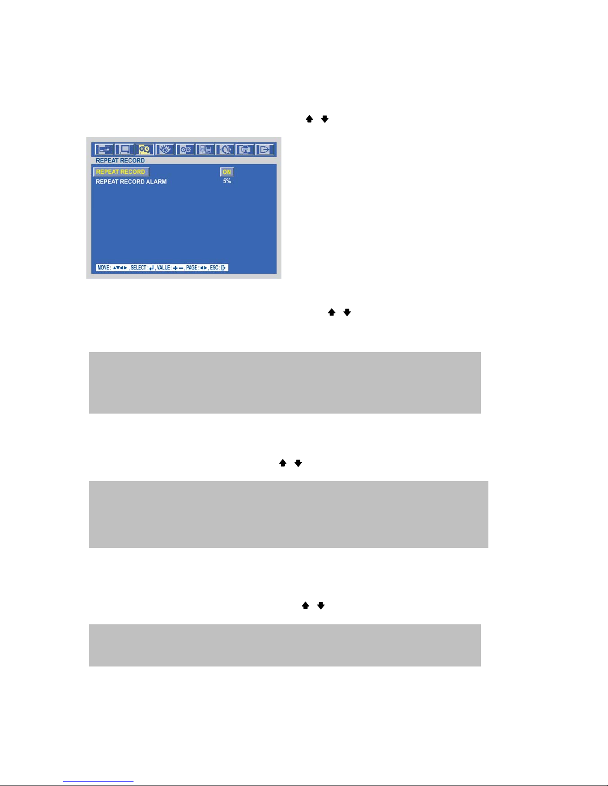
REPEAT RECORD
At the RECORD menu,
Move the cursor to the REPEAT RECORD using , buttons.
Press the ENTER button when the cursor is on the REPEAT RECORD and the following screen appears.
Use the (-), (+) buttons or jog dial to set “ON” or “OFF”.
It is possible to set a point of time to work the REPEAT RECORD ALARM.
Move the cursor to ”REPEAT RECORD ALARM” using , buttons and then select the desired value using
(-), (+) buttons or jog dial.
The value is from 5% to 10%.
To exit this REPEAT RECORD menu, press the ESC button.
PLAY MODE
At the RECORD menu,
Move the cursor to the PLAY MODE using , buttons.
Select the PLAY MODE using the (-), (+) buttons or jog dial.
BACKUP MODE
At the RECORD menu,
Move the cursor to the “BACKUP MODE” using , buttons.
Select the “BACKUP MODE” using the (-), (+) buttons or jog dial.
ON: The recorded data will be overwritten when it is a point of time to work the REPEAT RECORD.
REPEAT RECORD ALARM is the rest capacity of the HDD.
If you set “REPEAT RECORD ALARM” to 5%, alarm will work when the rest capacity of the HDD
is 5%.
AUTO : This DVR will automatically select playback in frame(two fields) or field to avoid
moving artifact.(Recommended)
FRAME : It will playback images in frame mode which is useful for recorded images in high frame rate.
This may occur moving artifact with recorded images in low frame rate.
FIELD : It will playback images in field mode. This reduces the resolution, but is suitable
for recorded images in low frame rate.
EVENT: Backup only when the event occurs.
MIRROR: Recording the same images in backup HDD.
OFF: Not backup.
Page 40
-
40
SPECIFICATION
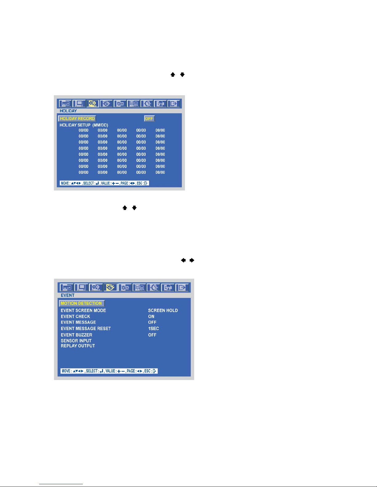
HOLIDAY
At the RECORD menu,
Move the cursor to the “HOLIDAY” using , buttons.
Press the “ENTER” button to set up “HOLIDAY” and the HOLIDAY menu screen appears.
Set up “ON” or “OFF” of HOLIDAY RECORD using the (-), (+) buttons or jog dial.
Move the cursor using , buttons and set up the value using the (-), (+) buttons or jog dial.
To exit this HOLIDAY menu, press the ESC button.
EVENT
To set up the EVENT menu,
Move the cursor to the EVENT icon using the , in the MENU screen.
Press the ENTER button when the cursor is on the EVENT icon and the following items appear.
MOTION DETECTION
Page 41
-
41
SPECIFICATION
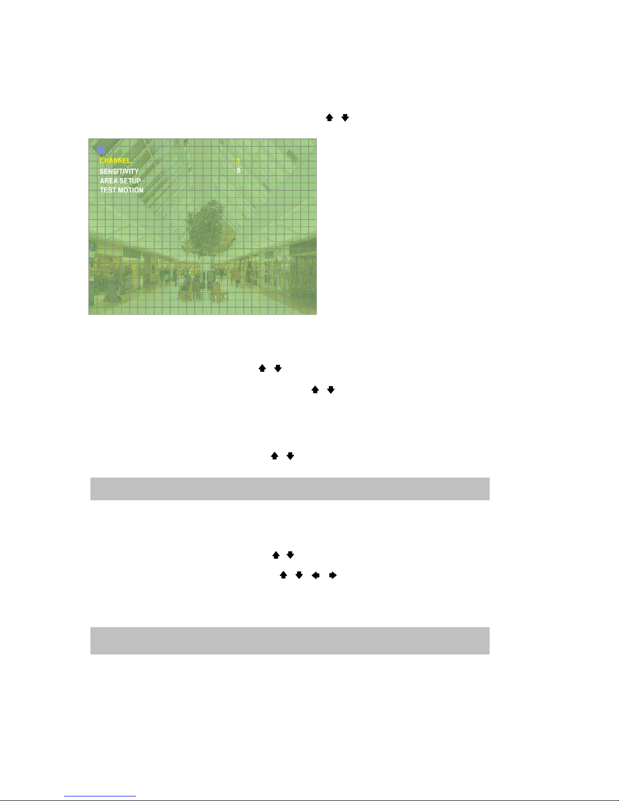
At the EVENT menu,
Move the cursor to the MOTION DETECTION using , buttons.
Press the ENTER button when the cursor is on the MOTION DETECTION and the following screen appears.
CHANNEL
At the MOTION DETECTION menu,
○
1
Move the cursor to CHANNEL using , buttons.
Select the desired channel using the (-), (+) buttons or jog dial.
Move the cursor to the EVENT MESSAGE using , buttons.
Select “ON” or “OFF” using the (-), (+) buttons or jog dial
SENSITIVITY
At the MOTION DETECTION menu,
○
1
Move the cursor to SENSITIVITY using , buttons.
Select the sensitivity level using the (-), (+) buttons or jog dial.
AREA SETUP
At the MOTION DETECTION menu,
Move the cursor to AREA SETUP using , buttons.
Press the ENTER button to set the motion detection area.
Select the motion detection area using the , , , buttons and then press the ENTER button to save
the area.
Turn the shuttle ring to the right to select all cells for motion detection and turn the shuttle ring to the left to
reset all area.
To exit this AREA SETUP, press the ESC button.
SENSITIVITY: The higher the number is, the more sensitive. 1(lowest) ~ 5(highest)
Mouse operation: Click the right button of mouse and drag to select the desired cells.
AREA SETUP GRID: 30 x 24
Page 42

-
42
SPECIFICATION
TEST MOTION
At the MOTION DETECTION menu,
Move the cursor to TEST MOTION using the , buttons.
Press the ENTER button to test the motion detection.
To exit this TEST MOTION, press the ESC button.
EVENT SCREEN MODE
At the EVENT menu,
Move the cursor to the EVENT SCREEN MODE using , buttons.
Select the EVENT SCREEN MODE using the (-), (+) buttons or jog dial.
EVENT CHECK
At the EVENT menu,
Move the cursor to the EVENT CHECK using , buttons.
Select “ON” or “OFF” using the (-), (+) buttons or jog dial
EVENT MESSAGE
At the EVENT menu,
Move the cursor to the EVENT MESSAGE using , buttons.
Select “ON” or “OFF” using the (-), (+) buttons or jog dial
EVENT MESSAGE RESET
At the EVENT menu,
Move the cursor to the EVENT MESSAGE RESET using , buttons.
Set the time to reset the event message using the (-), (+) buttons or jog dial.
EVENT BUZZER
At the EVENT menu,
Move the cursor to the EVENT BUZZER using , buttons.
Select “ON’ or “OFF” using the (-), (+) buttons or jog dial to set the event buzzer.
ON: The warning message will be displayed when the event occurs.
SCREEN HOLD: Keeping the current screen even if the event occurs.
EVENT FULL : Display the full screen of the channel which the event occurs.
EVENT MULTI : Display the multi-screen when the event occurs.
Page 43
-
43
SPECIFICATION
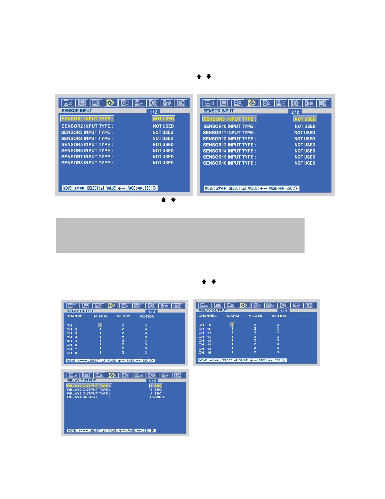
SENSOR INPUT
At the EVENT menu,
Move the cursor to the SENSOR INPUT using the , buttons.
Press the ENTER button when the cursor is on the SENSOR INPUT and the following 2 pages screen
appears
Select the desired channel using the , buttons.
Select the type of sensor which is connected with DVR using the (-), (+) buttons or jog dial.
To exit this SENSOR INPUT menu, press the ESC button.
RELAY OUTPUT
At the EVENT menu,
Move the cursor to the “RELAY OUTPUT” using the , buttons.
Press the ENTER button when the cursor is on the “RELAY OUTPUT” and the following screen appears.
Select the right sensor type according to the type of installed sensor with the unit.
NORMAL OPEN : The sensor is open in normal times.
NORMAL CLOSE : The sensor is close in normal times.
NOT INSTALLED: No sensors are connected to the DVR unit
Page 44
-
44
SPECIFICATION
Move the cursor using the , , , buttons and set up the value using the (-), (+) buttons or jog dial.
Press the button to see the next page.
To exit this screen, press the “ESC” button.
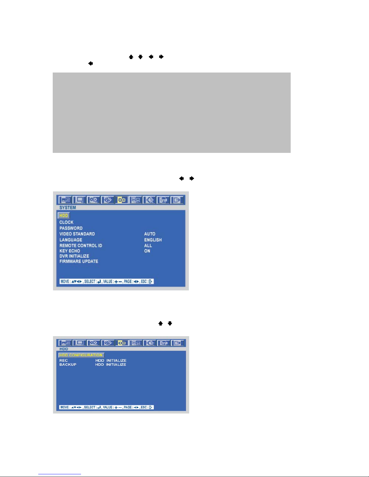
SYSTEM
To set up the SYSTEM menu,
Move the cursor to the SYSTEM icon using the , in the MENU screen.
Press the ENTER button when the cursor is on the SYSTEM icon and the following items appear.
HDD
At the SYSTEM menu,
Move the cursor to the HDD using the , buttons.
Press the ENTER button when the cursor is on the HDD and the following screen appears.
To exit this HDD menu, press the ESC button.
NOTE
- It is possible to set the RELAY OUTPUT of each channel in the type of event.
- Relay output is from 1 to 4 and it is possible to set the period of the relay output.
<RELAY 4 SELECT>
There are POWER, USER, NOT USED and HDD ERROR.
z POWER: The relay is working when power is off.
z USER: User can operate the relay manually.
Press the “FUNCTION” button to operate RELAY 4 manually.
NCNO: And then press the (+) button.
NO→NC: And then press the (-) button.
Press the “FUNCTION” button again if you want to exit this mode.
(You can also use this function through network viewer. Please refer to page 87.)
Page 45
-
45
SPECIFICATION
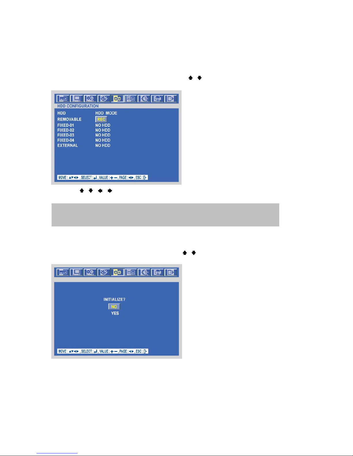
HDD CONFIGURATION
At the HDD menu,
Move the cursor to HDD CONFIGURATION using the , buttons.
Press the ENTER button when the cursor is on the HDD CONFIGURATION and the following screen appears.
Use the , , , buttons to move the cursor and use the (-), (+) buttons or jog dial to change the
value.
REC HDD INITIALIZE
At the HDD menu,
Move the cursor to REC HDD INITIALIZE using the , buttons.
Press the ENTER button when the cursor is on the REC HDD INITIALIZE and the following screen appears.
If you want to initialize, move the cursor to “YES” and then press the “ENTER” button.
If not, move the cursor to “NO” and then press the “ENTER” button.
To exit this screen, press the ESC button.
To exit this HDD menu, press the “ESC” button again.
HDD MODE
- REC: Normal and Event recording
- BACKUP: Only for backup
Page 46
-
46
SPECIFICATION
BACKUP HDD INITIALIZE
At the HDD menu,
Move the cursor to “BACKUP HDD INITIALIZE” using the , buttons.
Press the “ENTER” button when the cursor is on the “BACKUP HDD INITIALIZE” and the following screen
appears.
If you want to initialize, move the cursor to “YES” and then press the ENTER button.
If not, move the cursor to “NO” and then press the ENTER button.
To exit this screen, press the ESC button.
To exit this HDD menu, press the “ESC” button again.
Page 47
-
47
SPECIFICATION
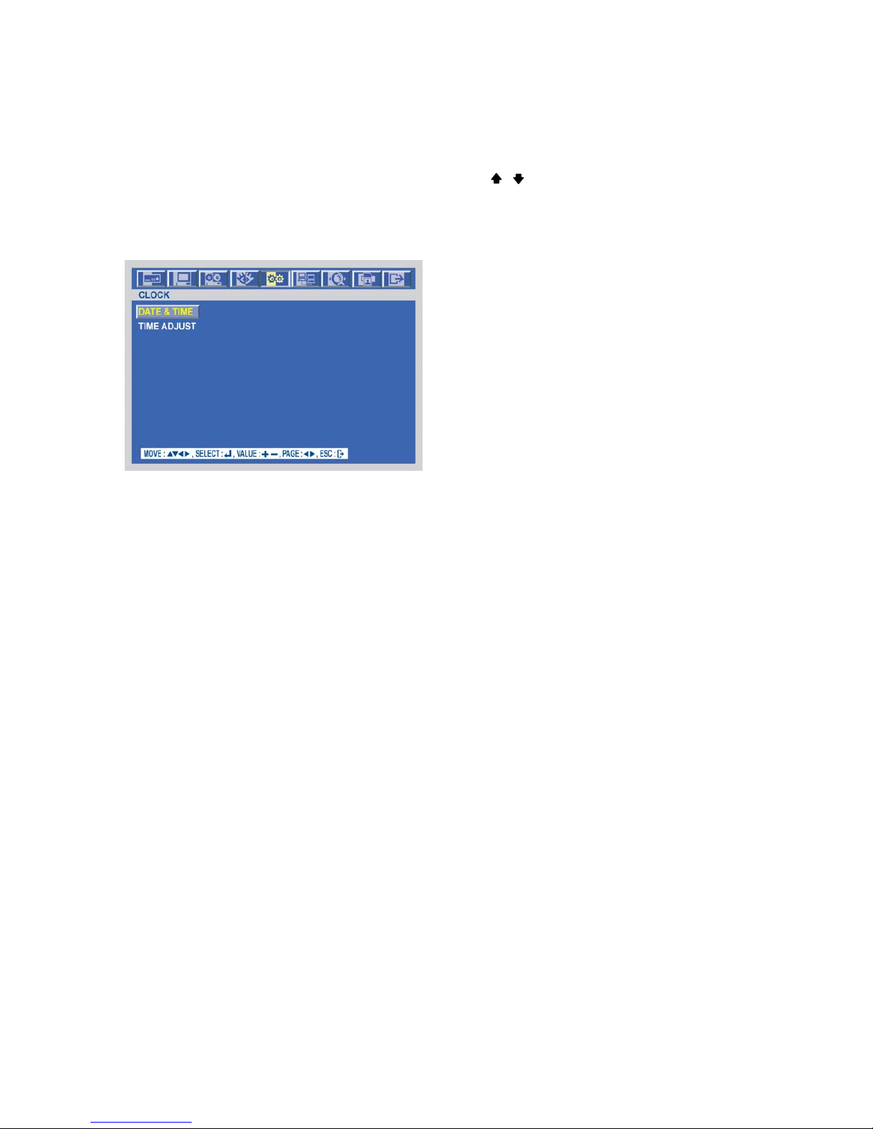
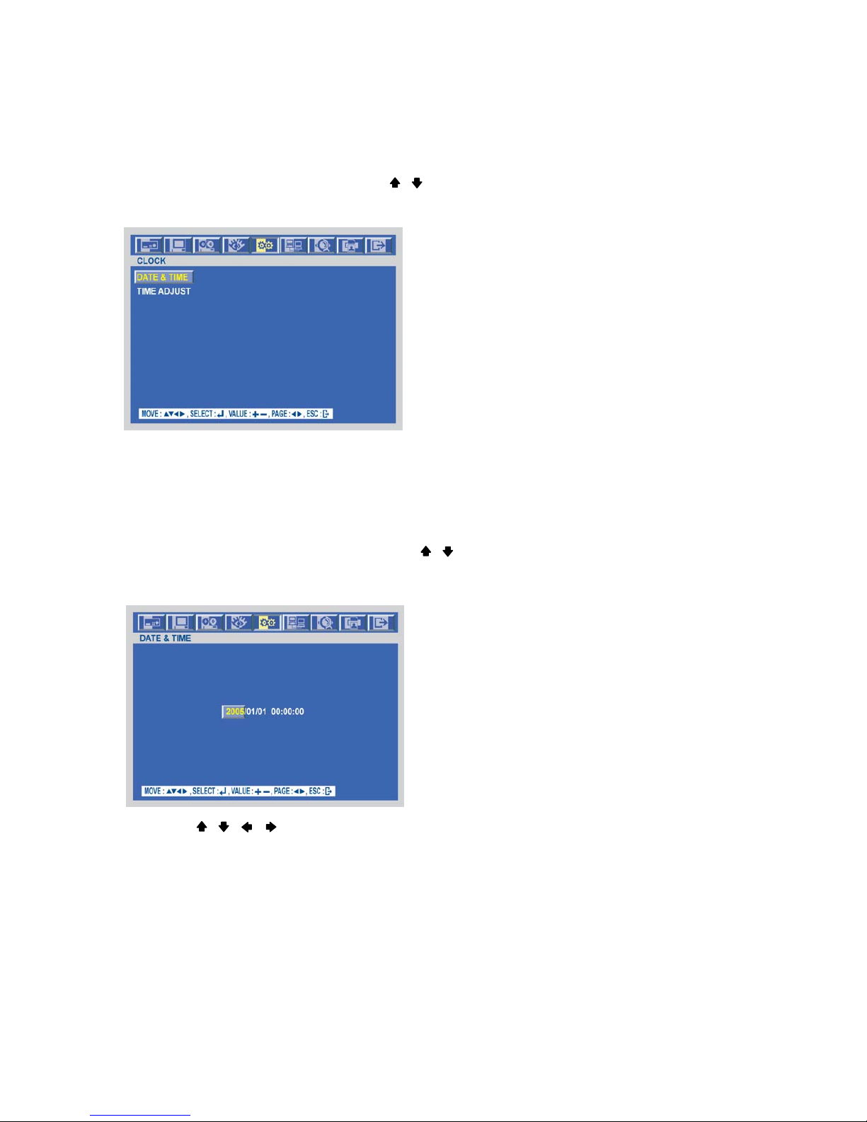
CLOCK
At the SYSTEM menu,
Move the cursor to the CLOCK using the , buttons.
Press the ENTER button when the cursor is on the CLOCK and the following screen appears.
DATE&TIME
At the CLOCK menu,
Move the cursor to the DATE&TIME using the , buttons.
Press the ENTER button when the cursor is on the DATE&TIME and the following screen appears.
Use the , , , buttons to move the cursor to the desired position of date or time.
Use the (-), (+) buttons or jog dial to modify the current date and time.
- DATE: YYYY/MM/DD YEAR/MONTH/DAY
- TIME : HH:MM:SS HOUR:MINUTE:SECOND
To exit this DATE & TIME screen, press the ESC button.
Page 48
-
48
SPECIFICATION
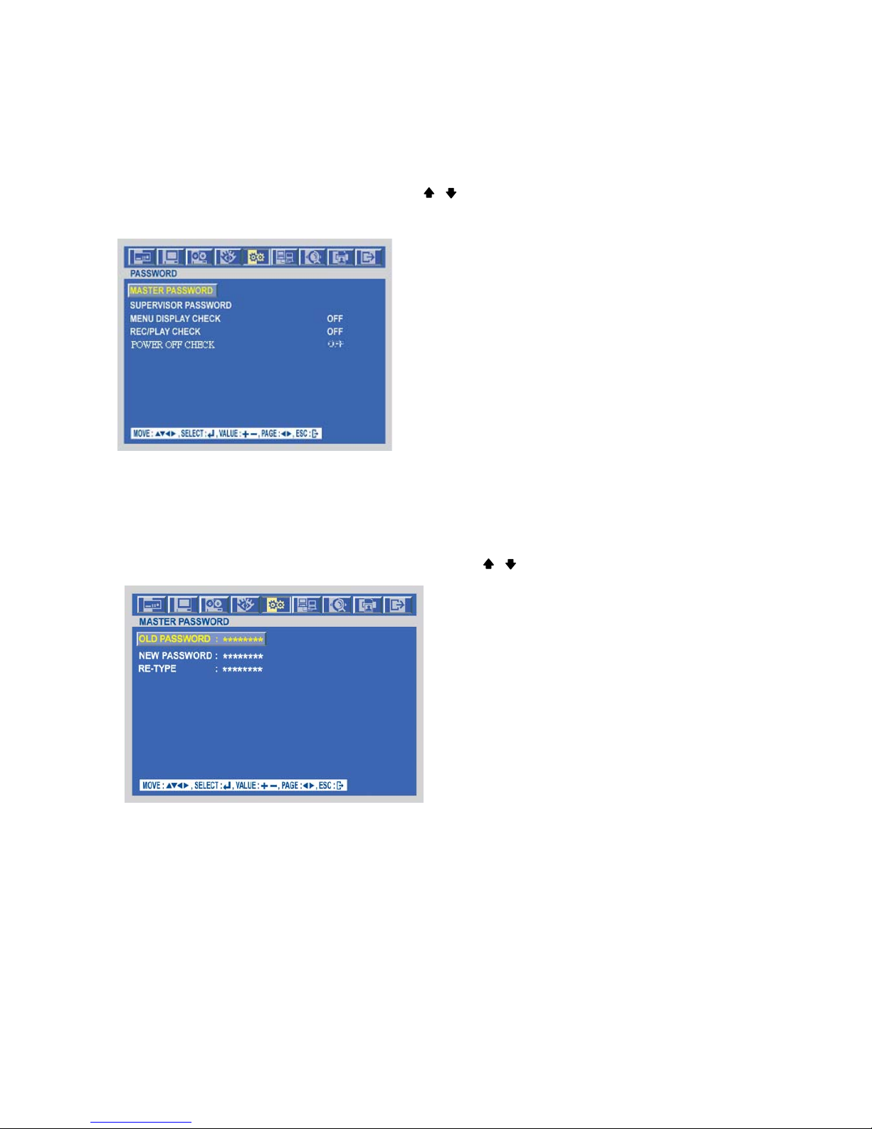
PASSWORD
At the SYSTEM menu,
Move the cursor to the PASSWORD using the , buttons.
Press the ENTER button when the cursor is on the PASSWORD and the following screen appears.
To exit this PASSWORD menu, press the ESC button.
MASTER PASSWORD
At the PASSWORD menu,
Move the cursor to the MASTER PASSWORD using the , buttons.
Press the ENTER button when the cursor is on the MASTER PASSWORD and the following screen appears.
Insert the current password in the eight digits marked ******** beside OLD PASSWORD using the CAMERA/
NUMBER INPUT buttons.
And then insert 8 numbers of NEW PASSWORD using the CAMERA/ NUMBER INPUT buttons.
And you have to insert the same numbers again to verify the password after entering the NEW PASSWORD.
To exit this MASTER PASSWORD menu, press the ESC button.
Page 49
-
49
SPECIFICATION
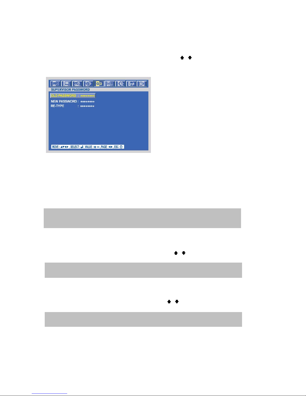
SUPERVISOR PASSWORD
At the PASSWORD menu,
Move the cursor to the SUPERVISOR PASSWORD using the , buttons.
Press the ENTER button when the cursor is on the SUPERVISOR PASSWORD and the following screen
appears.
Insert the current password in the eight digits marked ******** beside OLD PASSWORD using the CAMERA/
NUMBER INPUT buttons.
And then insert 8 numbers of NEW PASSWORD using the CAMERA/ NUMBER INPUT buttons.
And you have to insert the same numbers again to verify the password after entering the NEW PASSWORD.
To exit this SUPERVISOR PASSWORD menu, press the ESC button.
MENU DISPLAY CHECK
At the PASSWORD menu,
Move the cursor to the MENU DISPLAY CHECK using the , buttons.
Select “ON” or “OFF” to set up the MENU DISPLAY CHECK using the (-), (+) buttons or jog dial.
POWER OFF CHECK
At the PASSWORD menu,
Move the cursor to the POWER OFF CHECK using the , buttons.
Select “ON” or “OFF” to set up the POWER OFF CHECK using the (-), (+) buttons or jog dial.
If MENU DISPLAY CHECK is “ON”, the password will be required when you display or set the MENU.
The default is “OFF”.
If POWER OFF CHECK is “ON”, the password will be required when the system power is turned off.
The default is “OFF”.
NOTE: Supervisor can’t change or setup the MENU
You can use only 0~9 number buttons to setup the PASSWORD.
The default is 11111111.
Page 50

-
50
SPECIFICATION
REC/PLAY CHECK
At the PASSWORD menu,
Move the cursor to the REC/PLAY CHECK using the , buttons.
Select “ON” or “OFF” to set up the REC/PLAY CHECK using the (-), (+) buttons or jog dial.
VIDEO STANDARD
At the SYSTEM menu,
Move the cursor to the VIDEO STANDARD using the , buttons.
Select the desired value using the (-), (+) buttons or jog dial.
LANGUAGE
At the SYSTEM menu,
Move the cursor to the LANGUAGE using the , buttons.
Select the desired language using the (-), (+) buttons or jog dial.
REMOTE CONTROL ID
At the SYSTEM menu,
Move the cursor to the REMOTE CONTROL ID using the , buttons.
Set the REMOTE CONTROL ID using the (-), (+) buttons or jog dial.
KEY ECHO
At the SYSTEM menu,
Move the cursor to the KEY ECHO using the , buttons.
Set “ON” or “OFF” using the (-), (+) buttons or jog dial.
If you are operating more than one DVR in the same place and wish to use the remote controller, the
remote controller ID setup is required. Otherwise, do not change the default set value and “ON”
should be selected.
Creates the Remote controller ID
Select one of the numbers from 1 to 255, and then press the same number button on the supplied
remote controller before the operation.
If REC/PLAY CHECK is “ON”, the password will be required when you start to record or playback.
The default is “OFF”.
ON : The beep sounds when you press any buttons on the front panel.
OFF : The beep does not sound.
If you select “AUTO”, this DVR can detect NTSC/PAL automatically.
The default is “AUTO”.
Page 51
-
51
SPECIFICATION
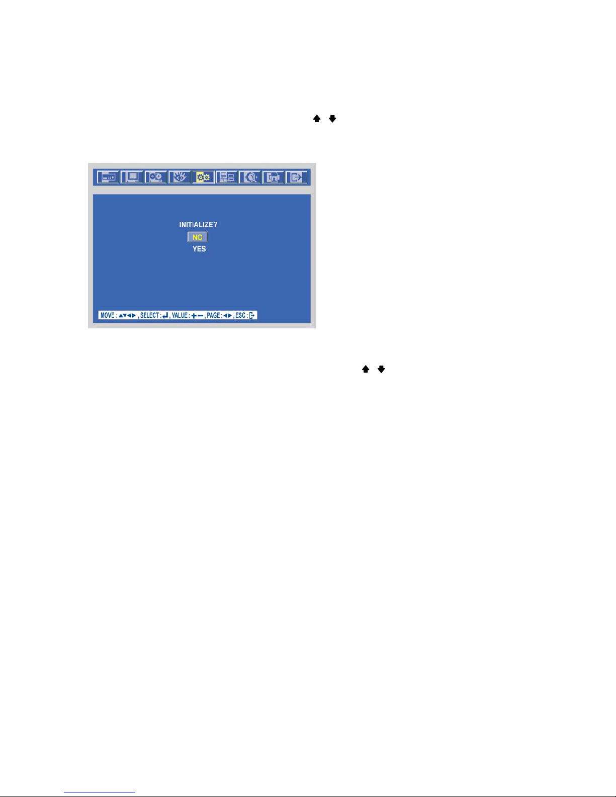
DVR INITIALIZE
At the SYSTEM menu,
Move the cursor to the DVR INITIALIZE using the , buttons.
Press the ENTER button when the cursor is on the DVR INITIALIZE and the following screen appears.
If you want to initialize, move the cursor to “YES” and then press the ENTER button. If not, move the cursor to
“NO” and then press the ENTER button. Use the , buttons to move the cursor.
To exit this DVR INITIALIZE screen, press the ESC button.
Page 52
-
52
SPECIFICATION
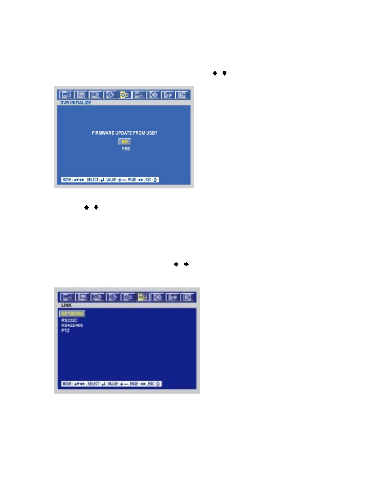
FIRMWARE UPDATE
At the SYSTEM menu,
Move the cursor to the FIRMWARE UPGRADE using the , buttons.
Press the ENTER button when the cursor is on the FIRMWARE UPDATE and the following screen appears.
If you want to update firmware using the USB port, move the cursor to “YES” and then press the ENTER
button. If not, move the cursor to “NO” and then press the ENTER button.
Use the , buttons to move the cursor.
To exit this FIRMWARE UPDATE screen, press the ESC button.
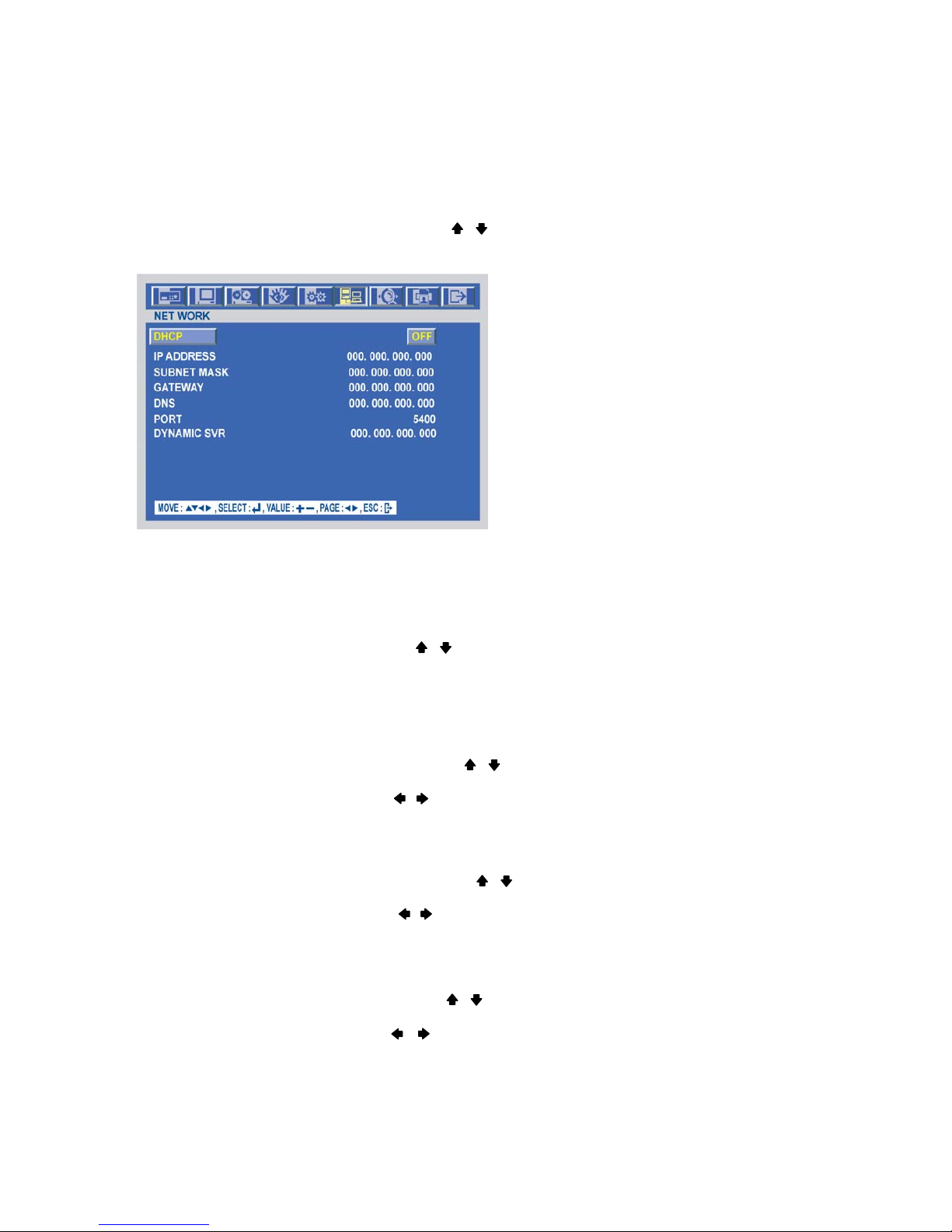
LINK
To set up the LINK menu,
Move the cursor to the LINK icon using the , in the MENU screen.
Press the ENTER button when the cursor is on the LINK icon and the following items appear.
Page 53
-
53
SPECIFICATION
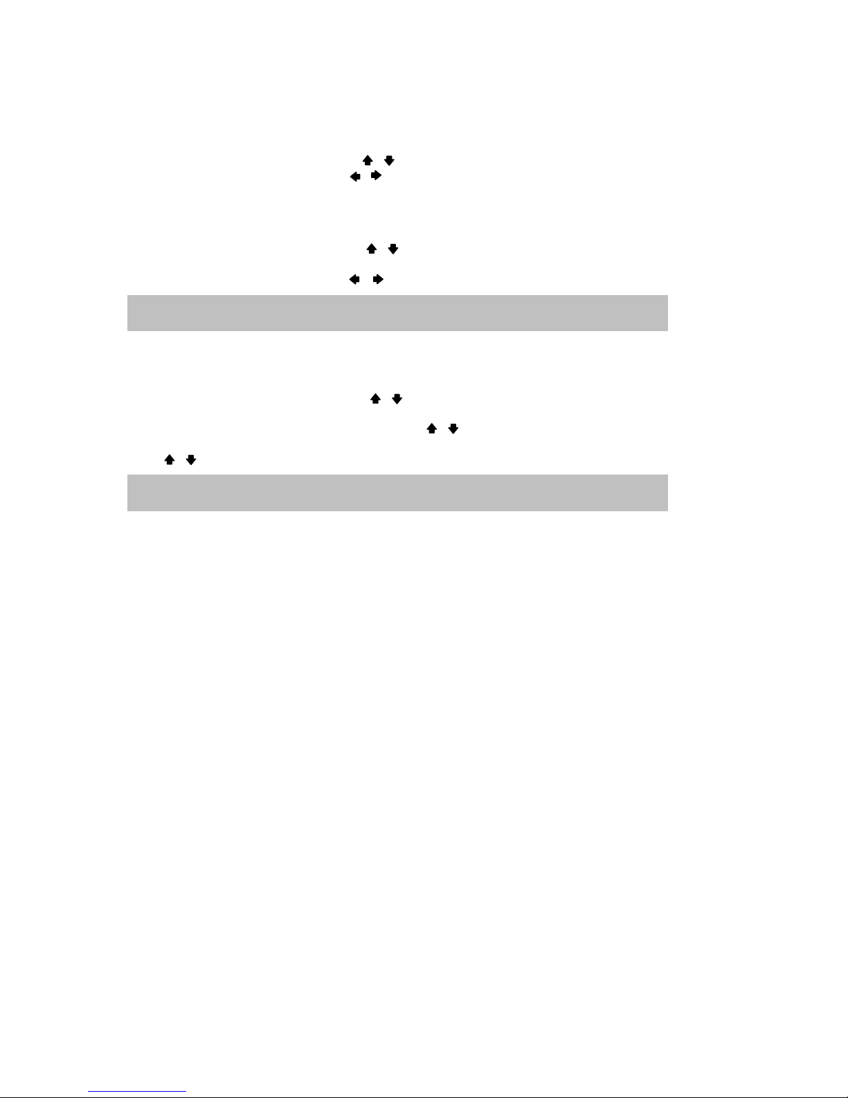
NETWORK
At the LINK menu,
Move the cursor to the NETWORK using the , buttons.
Press the ENTER button when the cursor is on the NETWORK and the following screen appears.
To exit this NETWORK menu, press the ESC button.
<Fixed IP>
DHCP
At the NETWORK menu,
Move the cursor to the DHCP using the , buttons.
Select “OFF” using the (-), (+) buttons or jog dial.
IP ADDRESS
At the NETWORK menu,
Move the cursor to the IP ADDRESS using the , buttons.
Select the desired position using the
, buttons and set the data value using the (-), (+) buttons or jog dial.
SUBNET MASK
At the NETWORK menu,
Move the cursor to the SUBNET MASK using the , buttons.
Select the desired position using the
, buttons and set the data value using the (-), (+) buttons or jog dial.
GATEWAY
At the NETWORK menu,
Move the cursor to the GATEWAY using the , buttons.
Select the desired position using the
, buttons and set the data value using the (-), (+) buttons or jog dial.
Page 54
-
54
SPECIFICATION
DNS
At the NETWORK menu,
Move the cursor to the DNS using the , buttons.
Select the desired position using the
, buttons and set the data value using the (-), (+) buttons or jog dial.
PORT
At the NETWORK menu,
Move the cursor to the PORT using the , buttons.
Select the desired position using the
, buttons and set the data value using the (-), (+) buttons or jog dial.
<Dynamic IP>
At the NETWORK menu,
Move the cursor to the DHCP using the , buttons.
Select “ON” using the (-), (+) buttons or jog dial.
Move the cursor to the DYNAMIC SVR using the , buttons.
Input the dynamic server IP using the (-), (+) buttons or jog dial to change the value and
the , buttons to move the cursor.
NOTE: Port setting on DVR and client viewer software must be matched.
NOTE: DHCP is a protocol for assigning dynamic IP addresses to devices on a network.
Page 55
-
55
SPECIFICATION
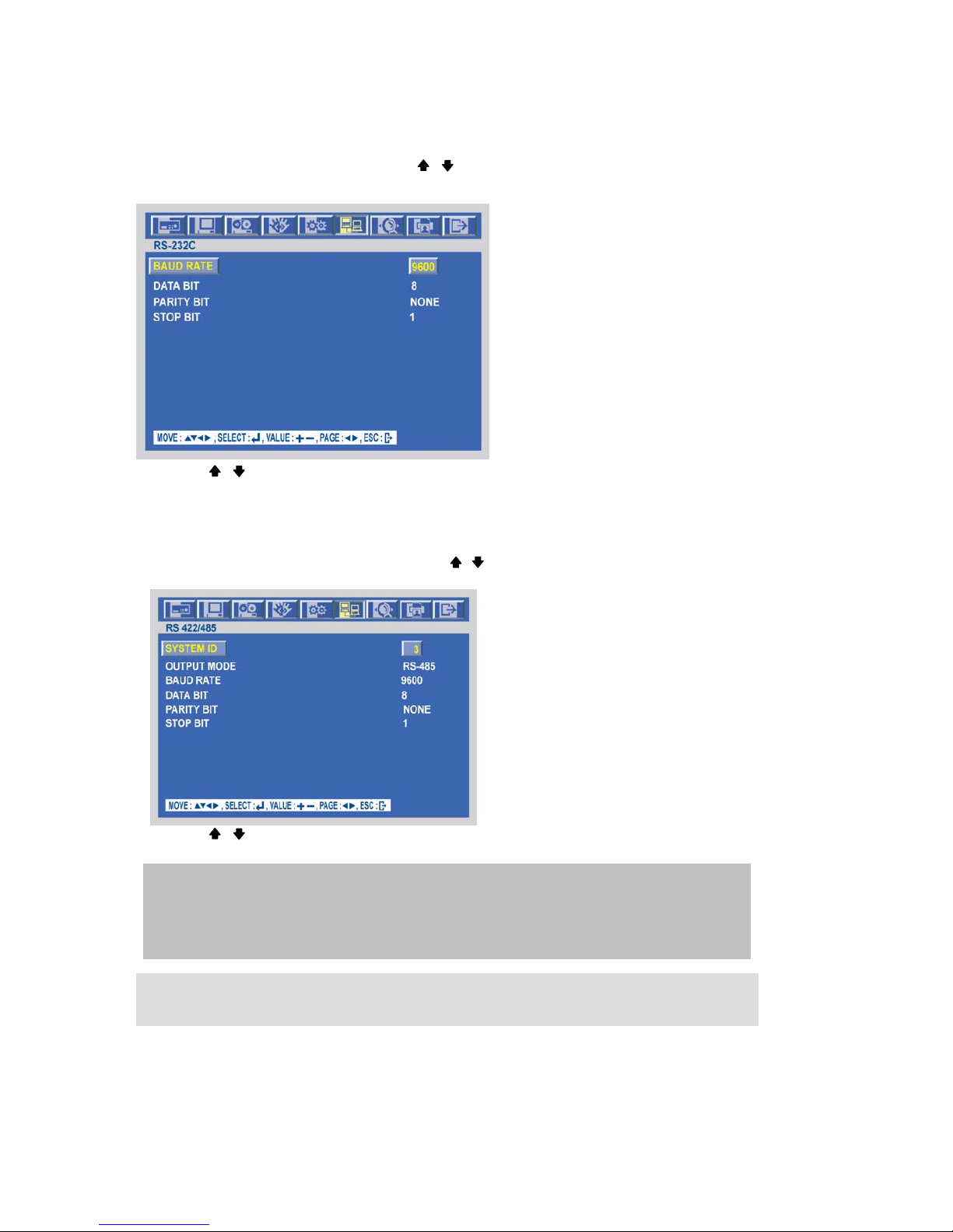
RS 232C
At the LINK menu,
Move the cursor to the RS232 using the , buttons.
Press the ENTER button when the cursor is on the RS232 and the following screen appears.
Use the , buttons to choose the item and use the (-), (+) buttons or jog dial to set the data value.
To exit this RS232 menu, press the ESC button.
RS 422 / 485
At the LINK menu,
Move the cursor to the RS422/485 using the , buttons.
Press the ENTER button when the cursor is on the RS422/485 and the following screen appears.
Use the , buttons to choose the item and use the (-), (+) buttons or jog dial to set the data value.
To exit this RS422/485 menu, press the ESC button.
NOTE
BAUD RATE : Data transmission speed per second.
DATA BIT : Data transmission bit.
PARITY BIT : Data transmission error checking.
STOP BIT : Data transmission ending bit
# CAUTION:
Turn off the power not to damage this unit when you connect RS-232C connector.
Page 56
-
56
SPECIFICATION
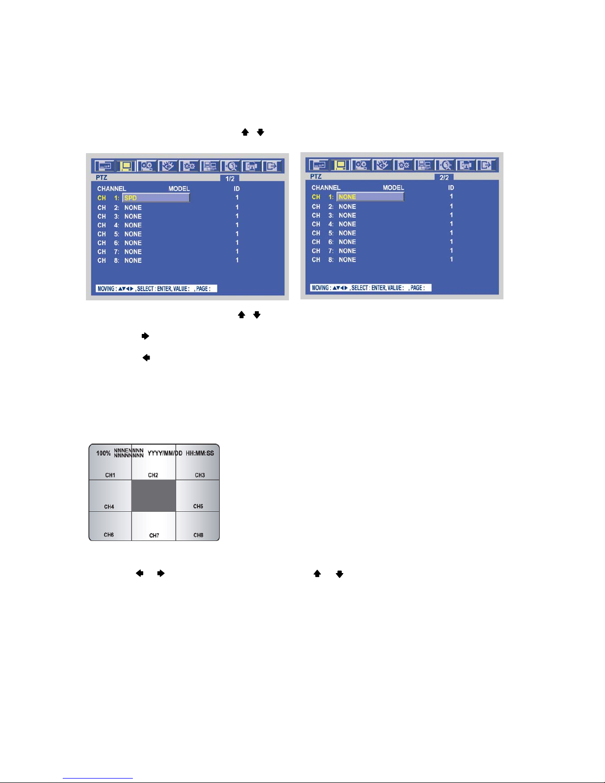
PTZ
At the SCREEN menu,
Move the cursor to the PTZ using , buttons.
Press the ENTER button when the cursor is on the PTZ and the following 2 pages screen appears.
Select the desired channel using , buttons.
Use the (-), (+) buttons or jog dial to select the right model of installed PTZ camera.
Press the button to set up a ID of the PTZ camera.
Use the (-), (+) buttons or jog dial to select the desired ID.
Press the button to see the next page.
To exit this PTZ menu, press the ESC button.
PTZ control in live view
Full channel, press the “PTZ” button to control pan, tilt and zoom functions of PTZ camera and the PTZ
channel, model name and ID will be displayed on the left side of the monitor as the following picture.
Press the desired camera button to be displayed.
Use the or button to pan left and right and the or button to tilt up and down.
Turn the SHUTTLE ring to zoom in and out.
Use the (-) or (+) button to focus. Or press the (AF) button for auto focusing.
Press the PTZ button again to exit the PTZ mode.
** Please refer to 6.2.8 PTZ setup of SCREEN menu, page 47.
Page 57
-
57
SPECIFICATION
PTZ PRESETTING
Press the “PTZ” button to enter PTZ mode.
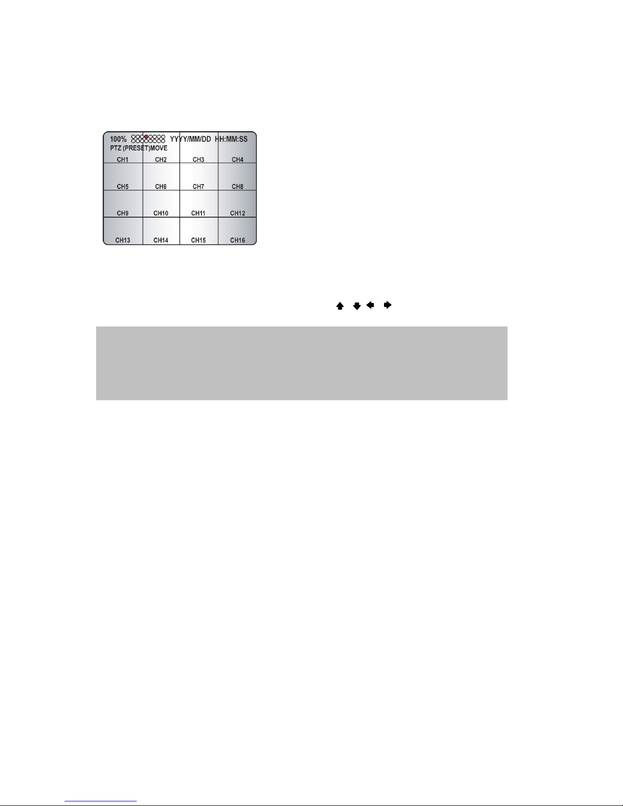
Press the “PRESET” button to enter PRESET mode and “PTZ(PRESET)MOVE”, OSD will be displayed on the
left side of the monitor.
Move to the desired preset location using the “NUMBER” buttons.
Press the “PRESET” button again and “PTZ(PRESET)SET”, OSD will be displayed on the left side of the
monitor.
Make the desired setting of the PTZ camera using the , , , , (-), (+) buttons.
Press the “NUMBER” button to set up the revised presetting.
PRESETS
- A preset is a user-defined camera position using pan and tilt, zoom, and focus commands.
This DVR has the Programming capacity for 16 preset locations.
- This DVR has RS-422/485 terminal block telemetry port on the rear panel.
KEY_MENU: open PTZ MENU
KEY_PRESET: Preset function key
KEY_ESC: clear preset point
KEY_FREEZE: call preset point
KEY_AUTO: Auto Pan
KEY_COPY: focus near
KEY_SEARCH: focus far
KEY_SLOW: Pan/tilt speed down
KEY_FAST: Pan/tilt speed up
JOG_LEFT: IRIS_CLOSE
JOG_RIGHT: IRIS_OPEN
Page 58
-
58
SPECIFICATION
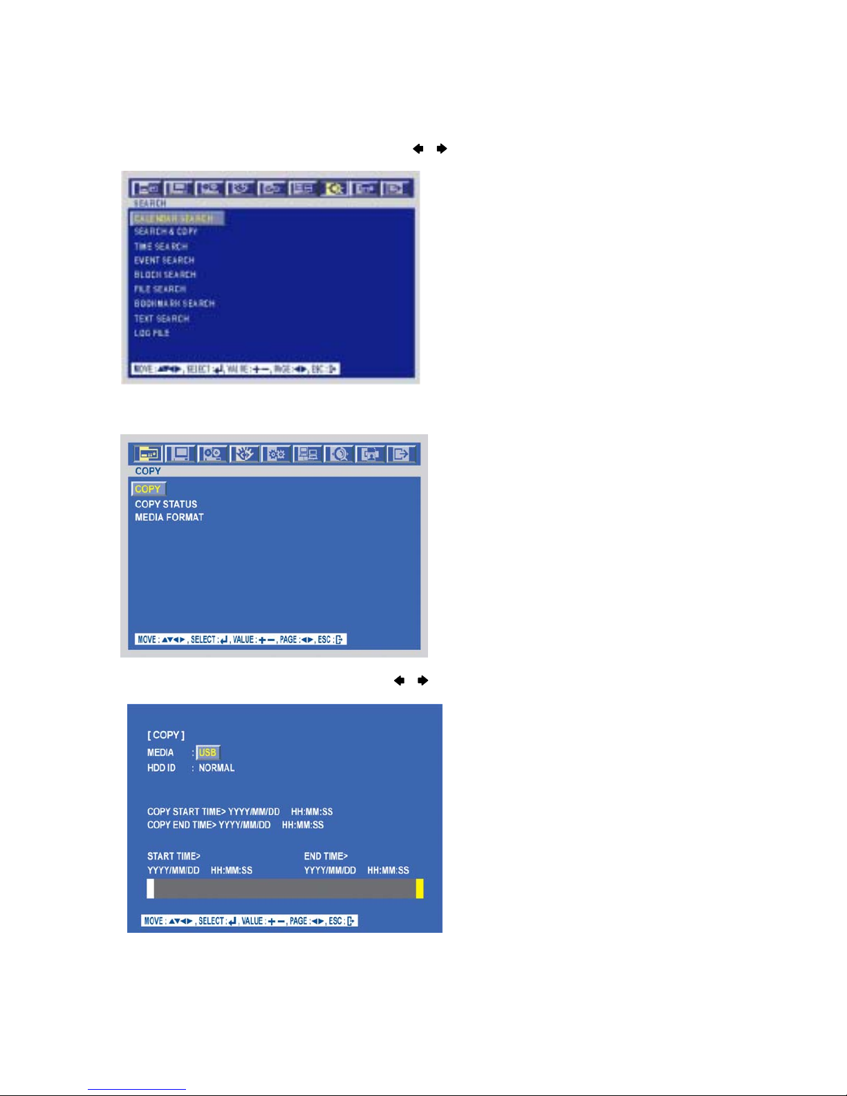
SEARCH
To set up the SEARCH menu,
Move the cursor to the SEARCH icon using the , in the MENU screen.
Press the ENTER button when the cursor is on the SEARCH icon and the following items appear.
COPY
Press the COPY button to copy the recorded images into other media and the COPY MENU screen appears.
To set up the COPY menu,
Move the cursor to the COPY icon using the , in the MENU screen.
Press the ENTER button when the cursor is on the COPY icon and the following items appear.
Page 59
-
59
SPECIFICATION
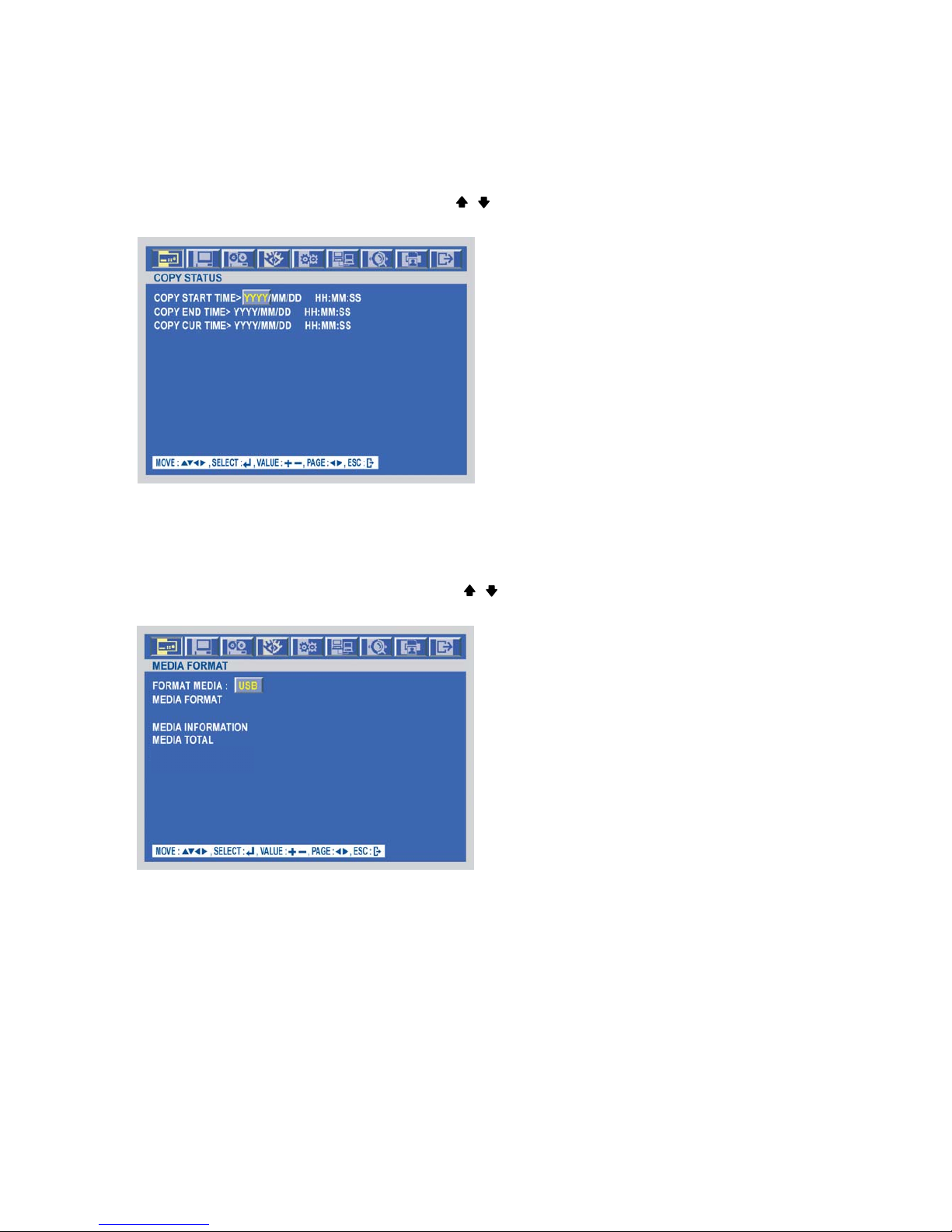
COPY STATUS
At the COPY menu,
Move the cursor to COPY STATUS using the , buttons.
Press the ENTER button to see the current copying status and the following screen appears.
MEDIA FORMAT
At the COPY menu,
Move the cursor to MEDIA FORMAT using the , buttons.
Press the ENTER button and the following screen appears.
Select formatting media using the (-), (+) button.
Move the cursor to MEDIA FORMAT and then press the “ENTER” button.
The message, “FORMATTING” will be displayed while formatting.
Page 60
-
60
SPECIFICATION
EXIT
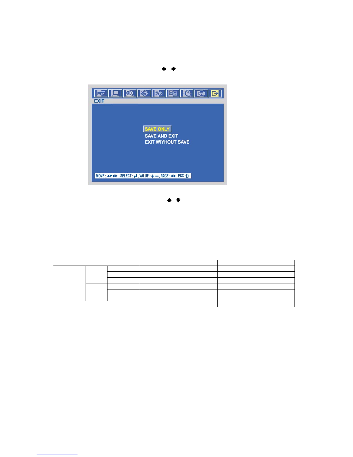
At the MENU screen,
Move the cursor to the EXIT icon using the , buttons.
Press the ENTER button when the cursor is on the EXIT icon and the following items appear.
Move the cursor to the desired item using the , buttons and press the ENTER button.
- SAVE ONLY : Select this item if you want only to save the changed setup.
- SAVE AND EXIT : Select this item if you want to save the changed setup and exit this screen.
- EXIT WITHOUT SAVE : Select this item if you want not to save the changed setup before
exiting this screen.
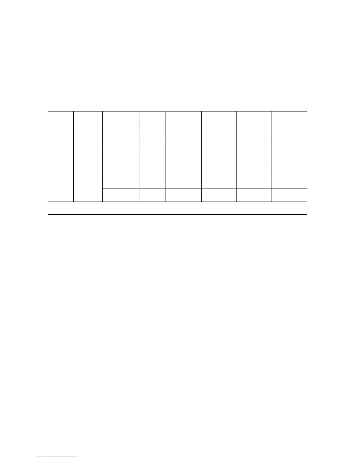
< Recording Speed Table >
*Note 1, 2 Unit : fps
Model 16120 8120
360 x 240 120 120
720 x 240 60 60
NTSC
720 x 480 30 30
360 x 288 100 100
720 x 288 50 50
Recording
Speed
PAL
720 x 576 25 25
Compression Method MPEG4 MPEG4
Page 61
-
61
SPECIFICATION
< Recording Time Table >
1. RECORDING CONDITIONS
Based on 120GB of storage with the installation of 1 camera.
This DVR can support up to 22TB with external HDD storage devices..
2. RECORDING TIME TABLE
VIDEO
SIGNAL
RECORD
IMAGE
IMAGE
QUALITY
IMAGE
SIZE
120fps(CIF) 60fps(CIF) 30fps(CIF) 15fps(CIF)
SUPERFINE
8448
Bytes
69 Hours 138 Hours 276 Hours 552 Hours
FINE
6688
Bytes
85 Hours 170 Hours 340 Hours 680 Hours
Color Bar
LOW
5344
Bytes
111 Hours 222 Hours 444 Hours 888 Hours
SUPERFINE
37300
Bytes
15 Hours 30 Hours 60 Hours 120 Hours
FINE
29400
Bytes
19 Hours 38 Hours 76 Hours 152 Hours
NTSC*
Cross
Hatch
LOW
22208
Bytes
25 Hours 50 Hours 100 Hours 200 Hours
* The NTSC signal mode is used for most of televisions produced in the U.S.
• The figures in the Recording Time Table were estimated under ideal recording conditions and may vary
from your actual recording situation.
• In the Recording Time Table, multiply by 2 for recording hours with an 240 GB HDD and 3 for recording
hours with a 360 GB HDD.
• The complexity of the image and the amount of motion recorded greatly influences the recording
capacity of your hard drive (HDD). The higher the frames per second and the higher the video quality
setting, the lower your HDD recording capacity will be. In the same manner, the lower the frames per
second setting and the lower the video quality setting, the higher your HDD recording capacity will be.
• Note that the lower frame rate does not mean a lower video quality. The image quality remains the
same whether the frames per second setting is set high or low. One frame per second is the same as
taking a photo every second.
• There are several factors that influence the recording capacity of your hard drive.
(a) The number of cameras used
(b) The complexity of the recording image
(c) The number of frame recorded per second
(d) The image quality setting – Superfine, Fine or Low
Page 62
-
62
NETWORK VIEWER INSTALLATION
Network Viewer
Installation of Network Viewer Software
System requirement
- Pentium III or above recommended
- O/S : Microsoft Windows 2000 / XP
- 128MB RAM or above recommended
- Super VGA 16M or above recommended
- 10/100 base T network card for LAN operation
Network Environment
Client PC DVR
Minimum More than 1Mbps More than 0.5Mbps
Recommended
(16 Frames/Sec)
More than 3Mbps More than 3Mbps
∗ Transfer rate of image varies with the number of client accessed to DVR.
Installation
To start the installation,
○
1
Start Windows 2000 or XP
○
2
Insert viewer Software CD into the CD-ROM drive.
○
3
Install ewer and locate the viewer.exe file on your
PC screen.
○
4
Simply double-click the icon to start.
○
5
viewer main menu controller will appear on the screen.
Connecting to DVR
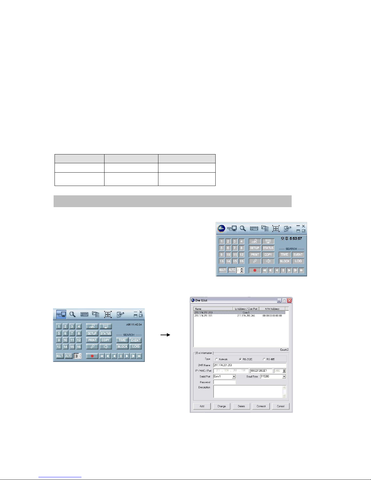
Please double-click the icon of Viewer, and then the following main menu controller will appear on
the PC screen.
NOTE : The software, Viewer® is compatible with Microsoft Windows 2000 / XP.
Page 63
-
63
NETWORK VIEWER INSTALLATION
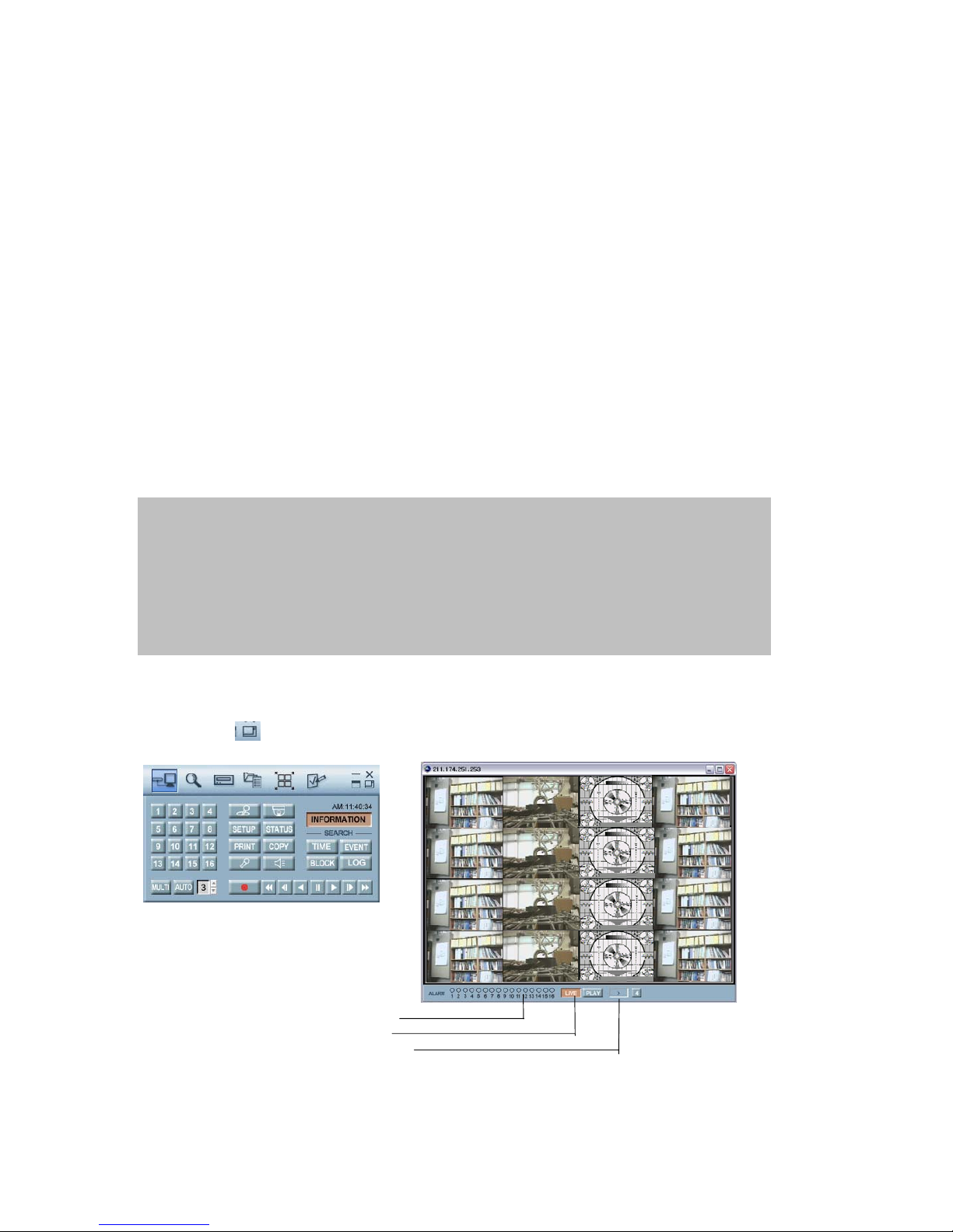
Add a new site information
○1 Click the “Select a DVR” button to display the DVR List on the screen.
○
2
Fill out Type, DVR Name, IP address and Password to add the desired units into the DVR
information box, and then click on the “Add” button to save the information.
Change the site information
○1 In case of any changes, type new information into the box after selecting the desired DVR on the
list.
○
2
Click the “Change” button to save the changes.
Delete the site information
○1 Select the desired DVR on the list, and then click the “Delete” button to erase the information on
the list.
Connect to a DVR.
○1 Select the desired DVR that you want to connect in the “DVR list”.
○
2
Select the necessary Information according to the connection type.
○
3
Click the “Connect” button or to access the DVR and the images screen will be displayed.
Viewer Screen
○
1
Click the button to see the full view window with control bar.
○2 Alarm Status
○3 LIVE
○
4
Playback
NOTE
You can connect 16 x 16(16 users x 16 units) windows at the same time but Master viewer is only one
by user.
PASSWORD
- T h e de fau lt p ass word is e ith e r of 11111111(M a ste r pa ssw ord ) and 22222222(Supervisor password).
- To change the password, please refer to the PASSWORD setup in Chapter 6 Set up MENU.
- The password must be the same as the registered site password.
Page 64
-
64
NETWORK VIEWER INSTALLATION
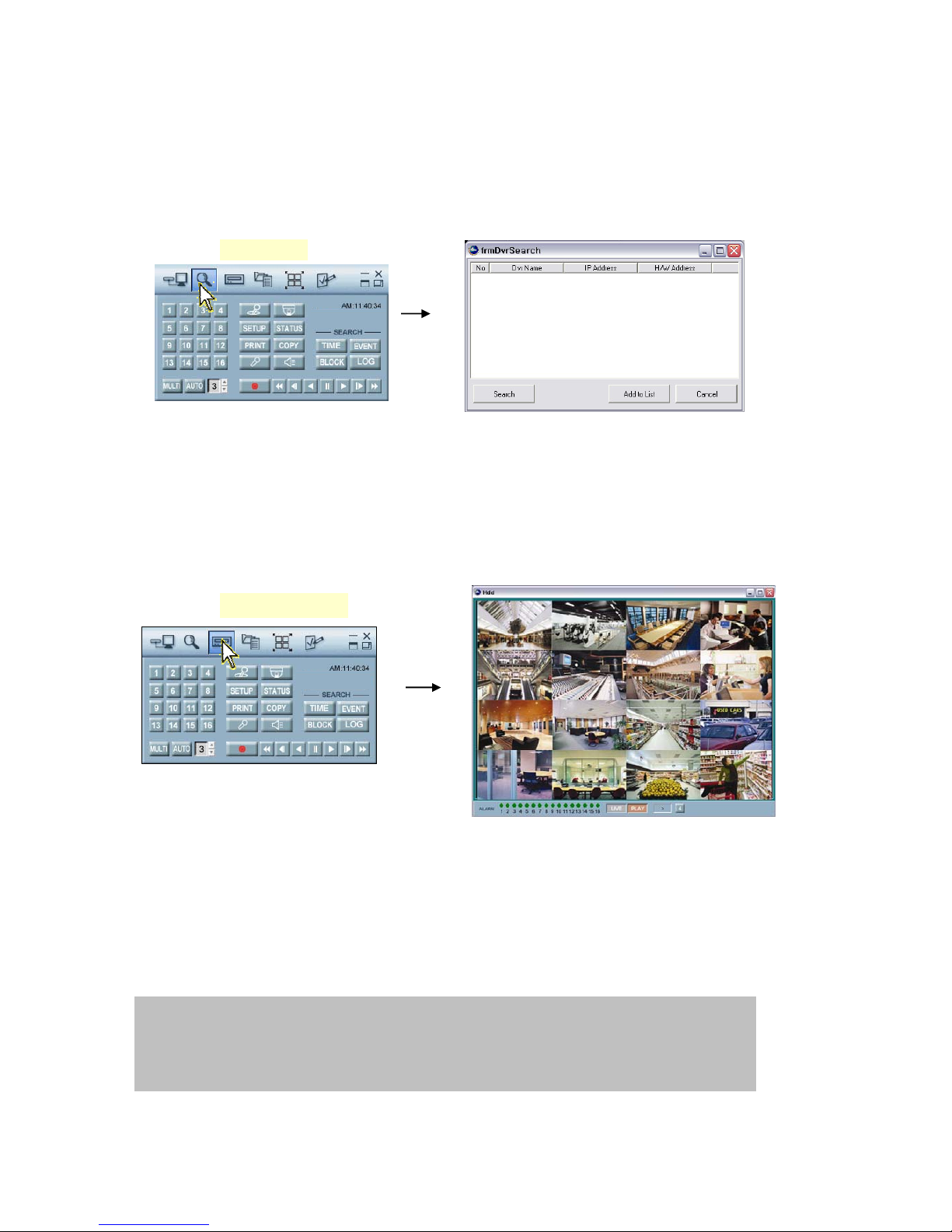
DVR search
This menu allows you to detect all the units on the local network.
○
1
Click “Search DVR” button to display the “Search” menu window.
○
2
Click the “Search” button, and then all the units on the local network will be detected and listed
on the screen.
○
3
Click the desired unit, and then click the “Add to list” button to add the unit into the “DVR list”.
HDD search
Connect DVR’s HDD with local PC, and then please double-click the Viewer® icon and the main
menu controller will appear on the PC screen.
○
1
Click the “HDD search” button and the view screen of HDD detected will appear on the PC screen.
○2 Click the desired one of the “SEARCH” buttons and SEARCH window will appear on the PC
screen.
○
3
Click the Play button after select of the desired Channel and Search Time in Time Search window.
○
4
Click the Search button after select of the desired Channel, Event type and Search Time in Event
Search window and then click the Play button after select of the desired list.
If you want to see the next list, click the Next button before playing.
○
5
Click the Search button after input of the desired Search Time in Block Search window and then
click the Play button after select of the desired list.
If you want to see the next list, click the Next button before playing.
HDD search
Search DVR
NOTE
- You can directly install the removable HDD rack from DVR to PC if compatible rack guide is
installed on the PC. In this case, please check the jumper setting for proper operation.
- You can also simply use external IEEE1394 HDD reader.
Page 65
-
65
NETWORK VIEWER INSTALLATION
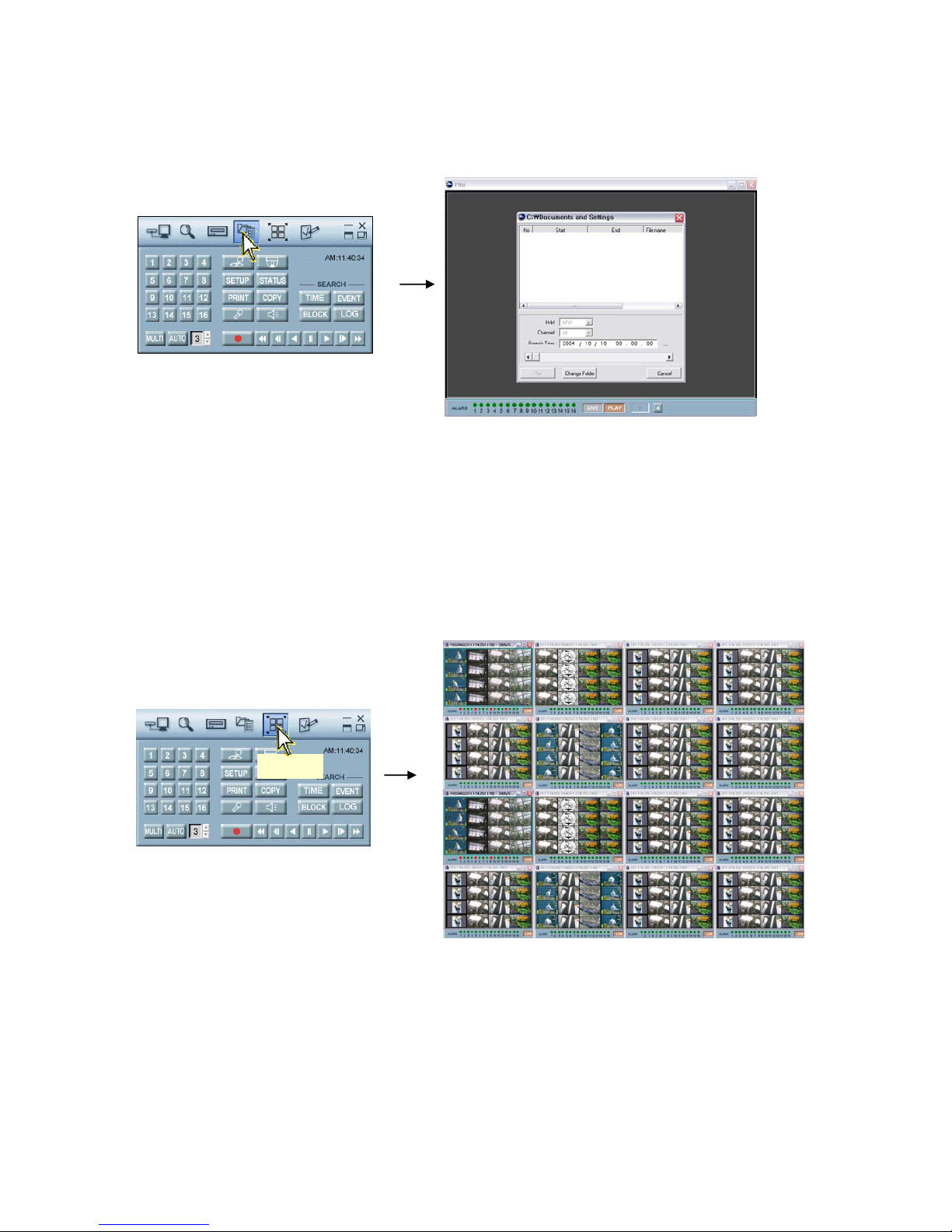
File Search
At the above main menu controller,
○
1
Click the “File Search” button and the “File list” window will appear on the PC screen.
○2 If you want to search images saved in CD-RW, DVD±RW or PC, insert the CD or DVD into your
PC and click the “File Search” button and the File Search window will appear.
○
3
Click the “Folder Select” button and then select the desired folder and then click the “OK” button.
○
4
Select the desired list and then click the “Play” button.
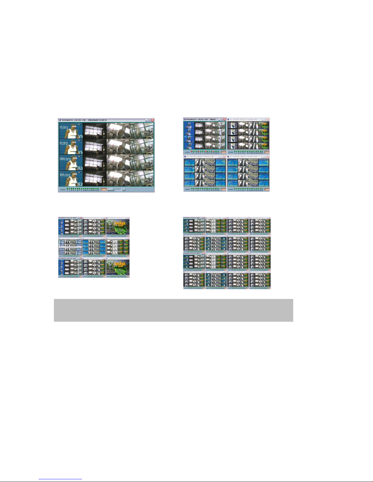
Arrange the screen
Use this button when you want to arrange the view screens.
Arrange
Page 66
-
66
NETWORK VIEWER INSTALLATION
At the above main menu controller,
○
1
Click the “Arrange” button when you access more than one DVR and the windows are arranged in
a grid on your PC screen.
* 1 site windows * 2 ~ 4 site windows
*5 ~ 9 site windows *10~16 site windows
NOTE - You can connect up to 16 DVRs with your PC simultaneously.
(16 users x 16 units: Master connection is only one.)
- With the windows arranged in a grid, double-click the desired to make it the full screen
Page 67
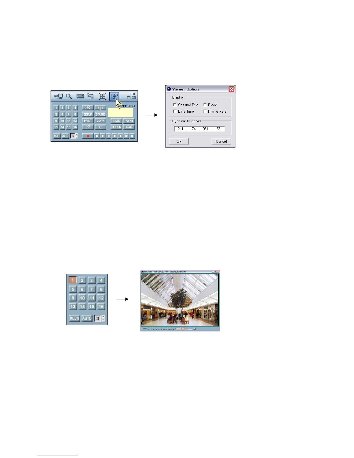
-
67
NETWORK VIEWER INSTALLATION
Option
Insert the CD into the CD-ROM drive, and then please double-click the icon of Viewer® and the
following main menu controller will appear on the PC screen.
○1 Click the “Option” button to change the other MENU setups.
○
2
Check the desired Option and then click the OK button.
- Channel Title: If you check “Channel Title”, the title of each channel will be displayed on the
viewer screen.
- Event: If you check “Event”, red OSD will be indicated on the event channel screen when any
event detected.
- Date Time: If you check “Date Time”, OSD of date and time will be displayed on the viewer screen.
- Frame Rate: If you check “Frame Rate”, transmitted frame rate will be displayed on the under
bar of viewer screen.
Control
Screen Display
: Images can be viewed in a full or multi format on each screen.
Full screen display
- Click the desired channel button and the full screen of the channel will be displayed.
.
Option
Page 68
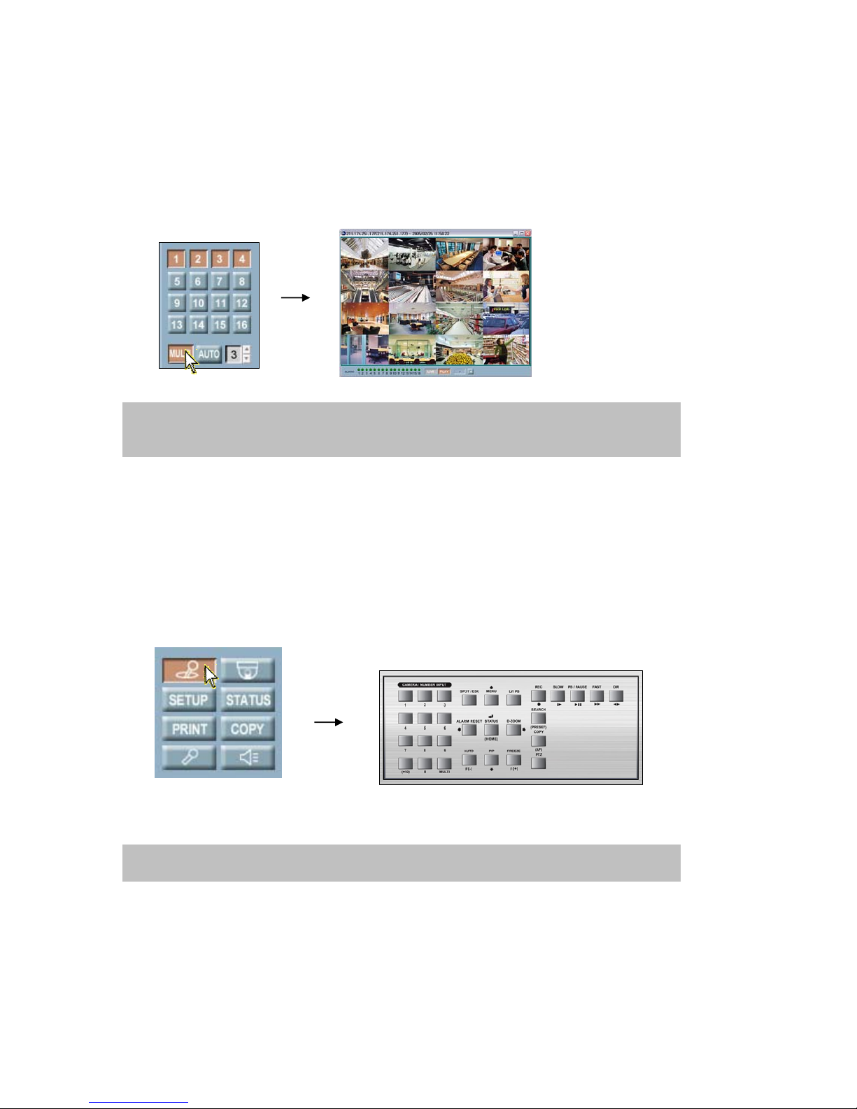
-
68
NETWORK VIEWER INSTALLATION
Multi-screen display
○
1
Click the “MULTI” button and the multi-screen will be displayed.
○
2
Click the “MULTI” button again to view other multi-screen.
c. Auto Sequence display
○
1
Click the “AUTO” button to view the full screen in sequence.
○
2
Change the interval time using the ▲,▼ buttons.
○
3
Click the “AUTO” button again to exit this mode.
Controller
: Click the “Controller” button and the control keys same as front panel of DVR will be displayed.
NOTE
Selecting a Multi-display may slow down the updates as multiple connections are made to the DVR
at the same time.
NOTE
If you need some more information about the control keys, please refer to Chapter 5 Operation.
Page 69
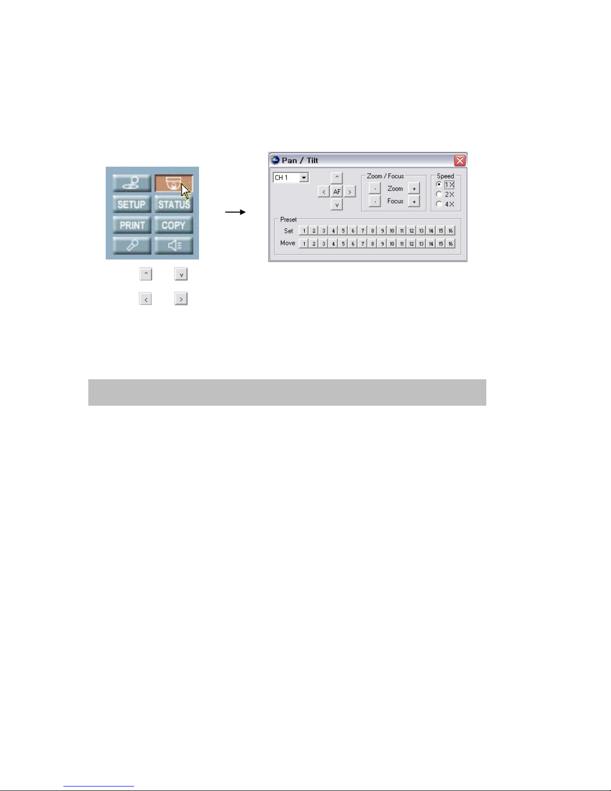
-
69
NETWORK VIEWER INSTALLATION
PTZ
: This menu allows you to control the PTZ camera through the network.
○1 Click the “PTZ” button to display the following PTZ controller.
○
2
Click the and button to tilt up or down.
○
3
Click the and button to pan left or right.
○
4
Click the “ZOOM(- or +)” button to zoom in or out.
○
5
Click the “FOCUS(- or +)” button to obtain the clearest picture.
○
6
And then select the speed.
- Preset setup
: A preset is user-defined camera position using pan and tilt, zoom, and focus commands. The DVR
has programming capacity for 16 preset locations.
-
Program a preset
○
1
Move the camera to a desired position using the PTZ control buttons.
○
2
After setting the PTZ camera, click one of the desired “Set” buttons, 1~16 of Preset.
○
3
To continue setting the preset camera, click another “Set” button after ○1. (Repeat ○1 and ○2)
-
Move to a preset
○
1
Click one of the “Move” buttons to move to the desired setting.
○
2
The camera will move to the programmed preset position.
NOTE
You can enter the PTZ mode only while connecting the PTZ camera.
Page 70
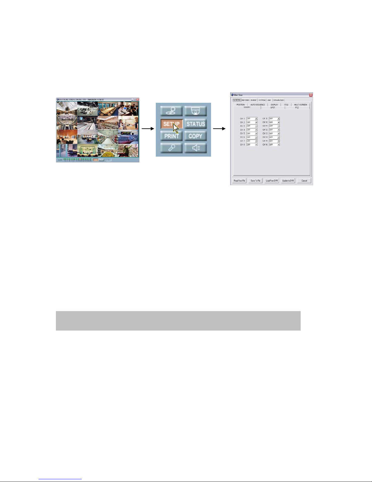
-
70
NETWORK VIEWER INSTALLATION
SETUP
You can modify DVR MENU setup through the network.
○
1
Click the “SETUP” button on the control menu bar to display the DVR setup screen after
connecting the view screen. (It is possible only for master connection.)
○
2
Click the “Save to file” button to store the current setup values.
○
3
Click the “Read from file” button to reload the stored setup values.
○
4
Click the “Load from DVR” button to call the current setup values from connected DVR.
○
5
Once the setup values are modified, click the “Update to DVR” button to update those values into
the DVR.
How to download firmware
○
1
Click the “SETUP” button on the control menu bar to display the DVR setup screen after
connecting the view screen. (It is possible only for master connection.)
○
2
Click the DOWNLOAD tap and you can see the “Firmware Download” button.
○
3
Click this “Firmware Download” button and browser window to find the desired file will be
displayed.
○
4
Select the downloading file and click the “OPEN” button to download.
NOTE
Please refer to Chapter 6 MENU setup for more information about DVR menu setup.
Page 71
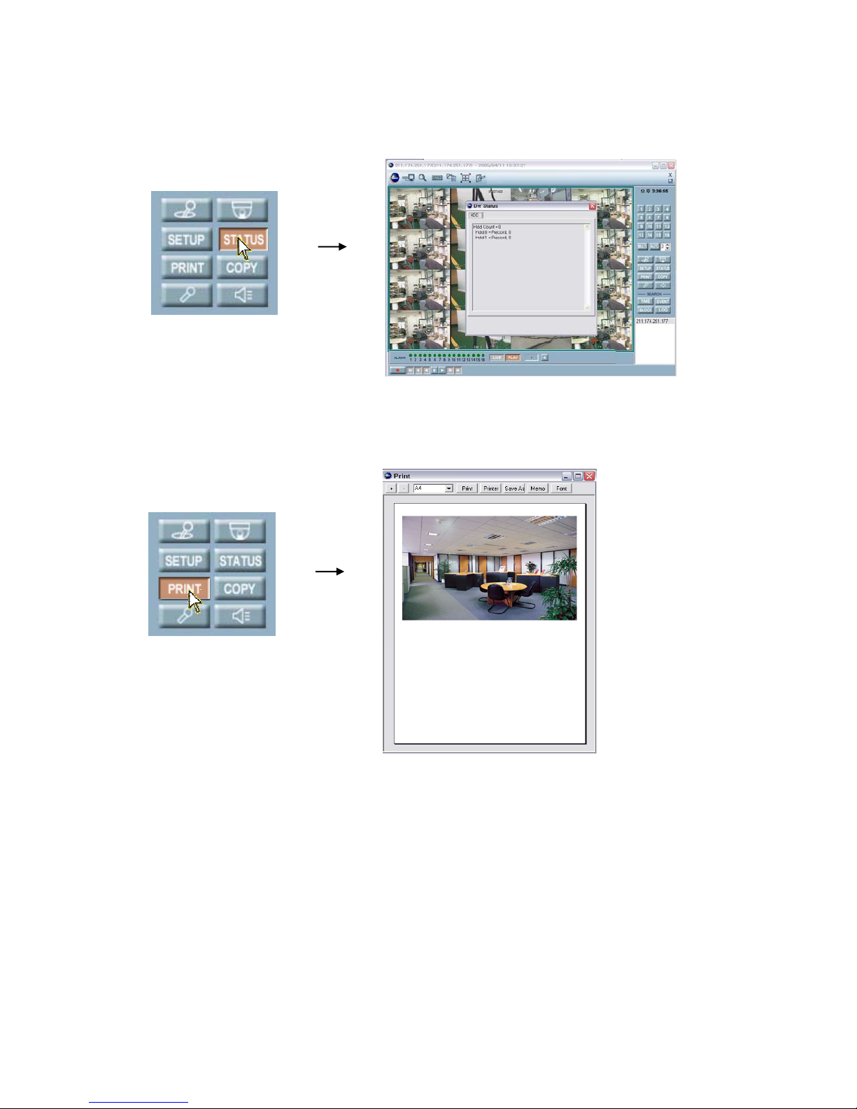
-
71
NETWORK VIEWER INSTALLATION
STATUS
○1 Click the “STATUS” button on the control menu bar to display the DVR status after connecting the
view screen.
PRINT
After connecting the view screen,
○
1
Click the “PRINT” button on the control menu bar to print the desired image.
○
2
And the preview window will be displayed as the above picture.
○
3
Set up the desired option and then click the Print button of the preview window.
Page 72
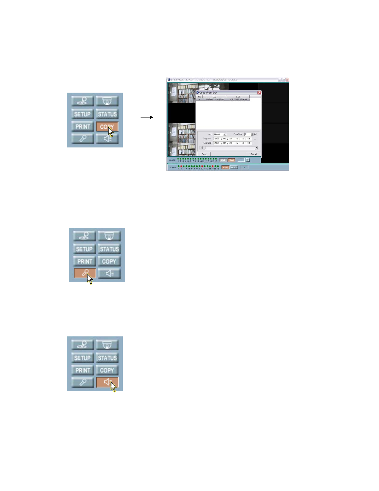
-
72
NETWORK VIEWER INSTALLATION
COPY
After connecting the view screen,
○
1
Click the “COPY” button on the control menu bar to copy the desired image.
○
2
The Copy control window will appear.
○
3
Click the “Copy” button of the control window after setting the desired HDD and the time.
AUDIO IN
After connecting the view screen,
○
1
Click the “Audio In” button on the control menu bar to input the audio.
○
2
Sound of your PC will travel into the DVR.
AUDIO OUT
After connecting the view screen,
○
1
Click the “Audio Out” button on the control menu bar to output the audio.
○
2
You can hear the DVR sound from the speaker of your PC.
Page 73
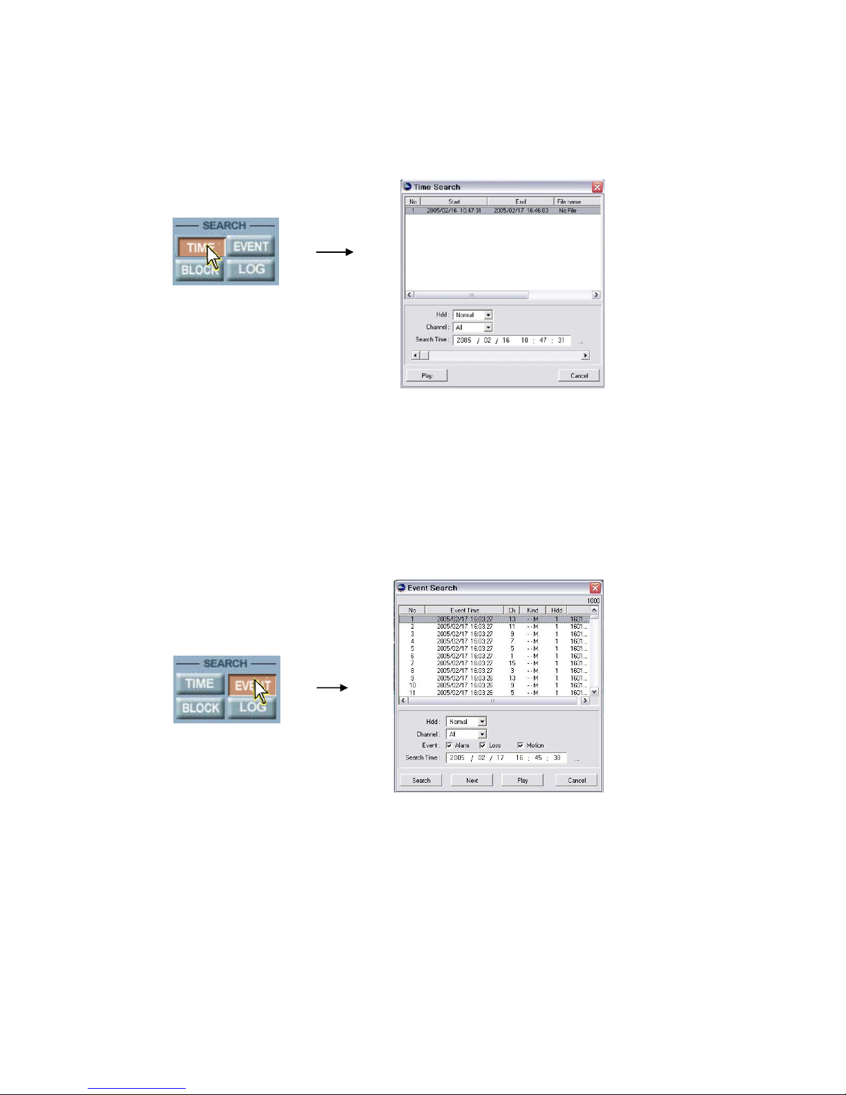
-
73
NETWORK VIEWER INSTALLATION
TIME SEARCH
: You can search and playback the images by the time.
After connecting the view screen,
○
1
Click the “TIME” button on the control menu bar to display the Time Search window.
○
2
Select the desired HDD mode in the HDD dropdown list, and then click the “Search” button.
○
3
When the recorded time information appears, select the desired “HDD” and the “Channel” and set
the “Search Time” for playback.
○
4
Click the “Play” button to display the images on the screen.
EVENT SEARCH
: You can review the event list that was triggered on the DVR.
After connecting the view screen,
○
1
Click the “EVENT” button on the control menu bar to display the Event Search window.
○
2
Select the desired HDD mode, Channel and the Event type in Event Search window, and then set
the Search Time
○
3
And then click the “Search” button.
○
4
When the recorded event list appears, select the desired list.
Click the “Play” button to display the images on the screen.
Page 74
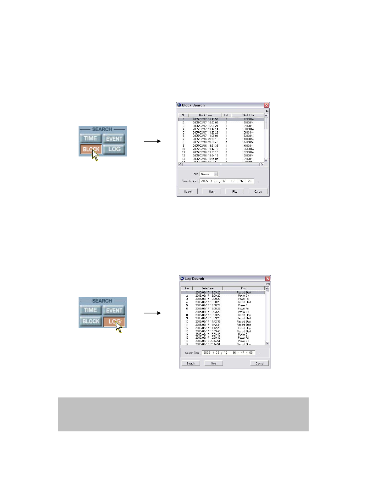
-
74
NETWORK VIEWER INSTALLATION
BLOCK SEARCH
: You can search and playback the images by the block.
After connecting the view screen,
○
1
Click the “BLOCK” button on the control menu bar to display the Block Search window.
○
2
Select the desired HDD mode and set the Search Time, and then click the “Search” button.
○
3
When the list appears, select the desired list.
○
4
Click the “Play” button of Block Search window to display the images on the screen.
Click the “Next” button to search the next list.
LOG SEARCH
: You can search and playback the images by logging.
○
1
Click the “LOG” button on the control menu bar to display the Log Search window.
○
2
Set the Search Time, and then click the Search button.
○
3
Click the “Next” button to search the next list.
NOTE: When the DVR is in Setup mode, this search function will not be performed.
- Normal HDD: Hard Disk Drive installed in the DVR
- Backup HDD: Hard Disk Drive installed in the DVR to backup(Event backup or Mirroring).
- R-HDD: Removable Hard Disk Drive installed in the DVR
Page 75
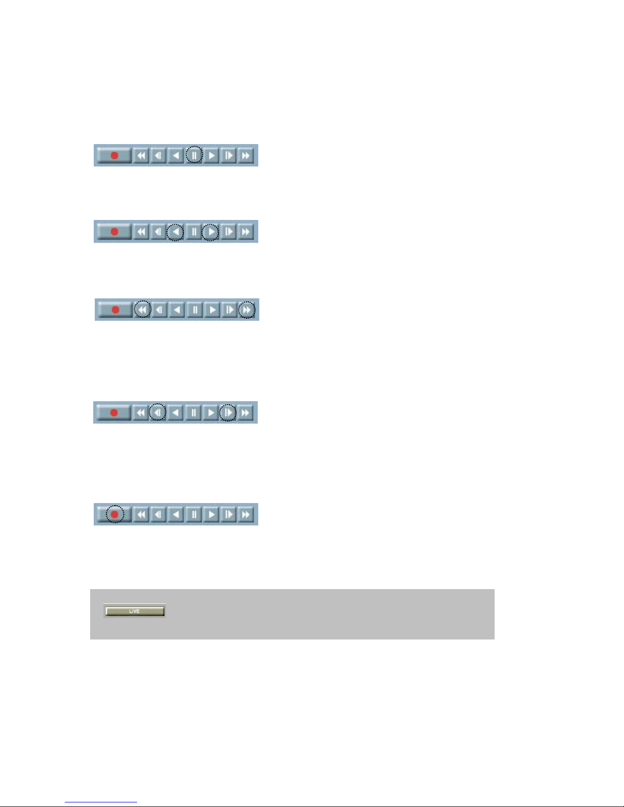
75
NETWORK VIEWER INSTALLATION
Key Information
PAUSE
○
1
Click this button to pause the images during the playback or live.
PLAY (Reverse & Forward)
○
1
Use these buttons to playback images at normal speed in either direction.
FAST (Reverse & Forward)
○
1
Use these buttons to playback images faster than normal speed in either direction.
○
2
Multiple clicks of these buttons will increase the fast forward & the reverse speed.
○
3
Various fast speed from x2 up to x128.
SLOW (Reverse & Forward)
○
1
Use these buttons to playback images faster than normal speed in either direction.
○
2
Multiple clicks of these buttons will decrease the fast forward & the reverse speed.
○
3
Various slow speed from x2 up to x128.
RECORD
○
1
To record the image of a channel(s) into the remote site PC, click this Record button.
○
2
Click the Record button again to stop recording.
○
3
The images will be stored in save folder of your PC.
○
4
Click the FILE Search button to find the saved images.
- During the playback mode, click the LIVE button to convert the screen into the
live display mode.
- You must use this Viewer® to replay the stored images in the PC.
Page 76
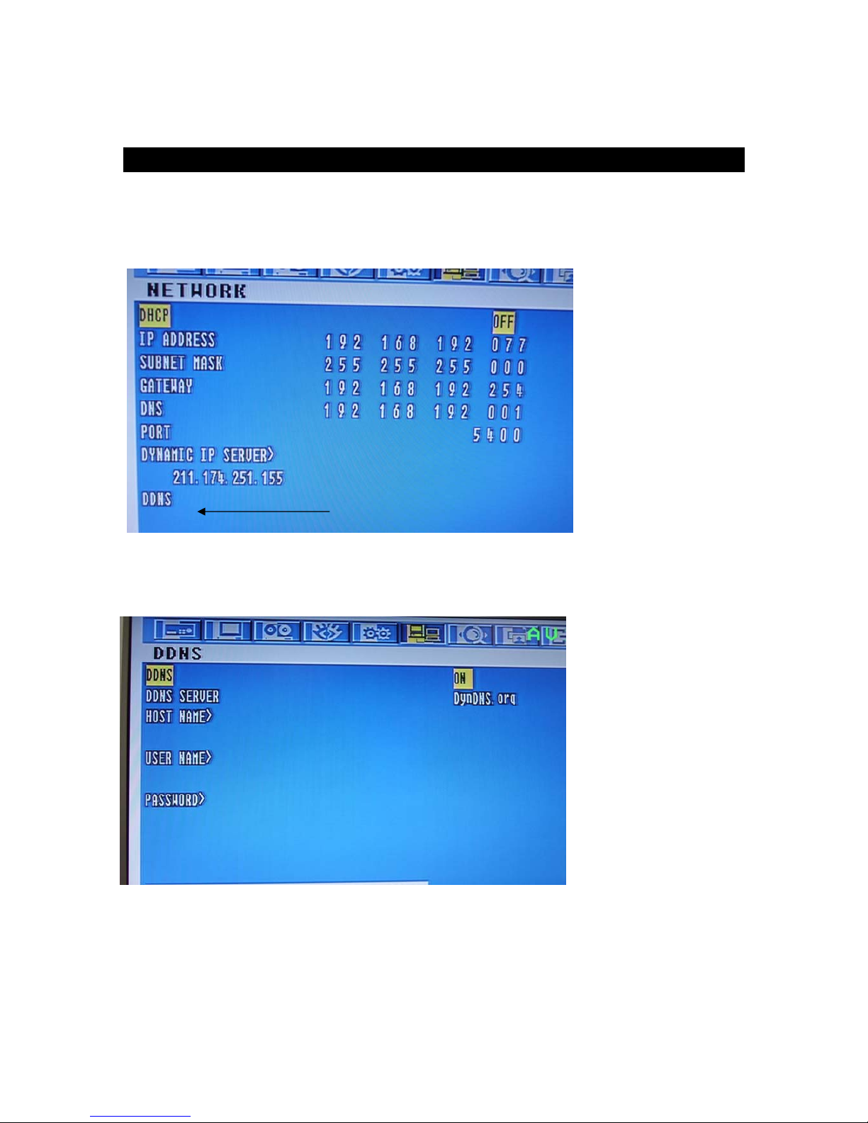
76
NETWORK VIEWER INSTALLATION
Select DDNS mode ON.
Notice: DDNS function support update.
ENTER
Page 77
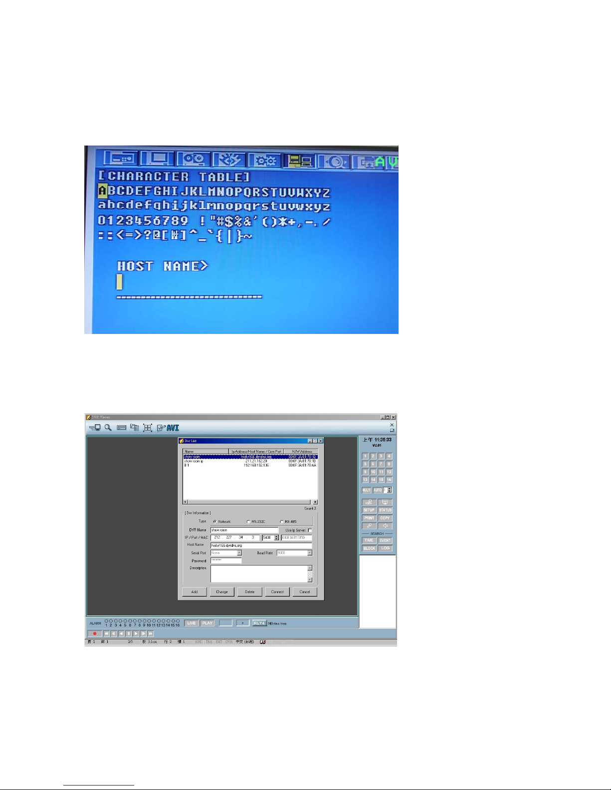
77
NETWORK VIEWER INSTALLATION
Insert Host name, User name and password with character table.
Net viewer DDNS mode:
Page 78
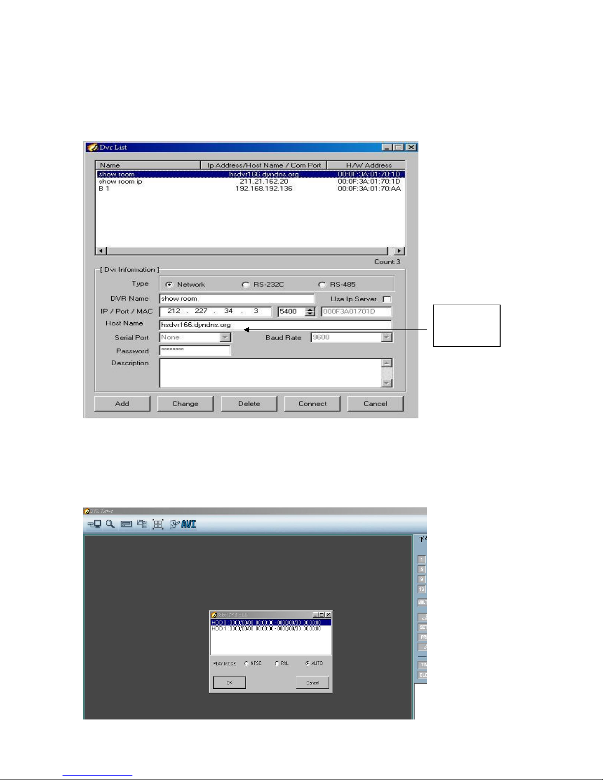
78
NETWORK VIEWER INSTALLATION
Type in DDNS host name, and then add to list. Host name is the priority if there is an IP
address is still fill in.
Host name should be left blank if IP address is used.
HDD is readable in PC with netveiwer,
Please select NTSC or PAL mode if the video system format displays different to your
recorded format.
DDNS
Host name
Page 79

79
NETWORK VIEWER INSTALLATION
 Loading...