

Page 1
TM
Model TEMPAL
Temperature Over Video
Owner’s Manual
15540 Herriman Blvd. Noblesville, IN 46060 - www.security-labs.com
Customer Support 1-800-774-0284
Page 2
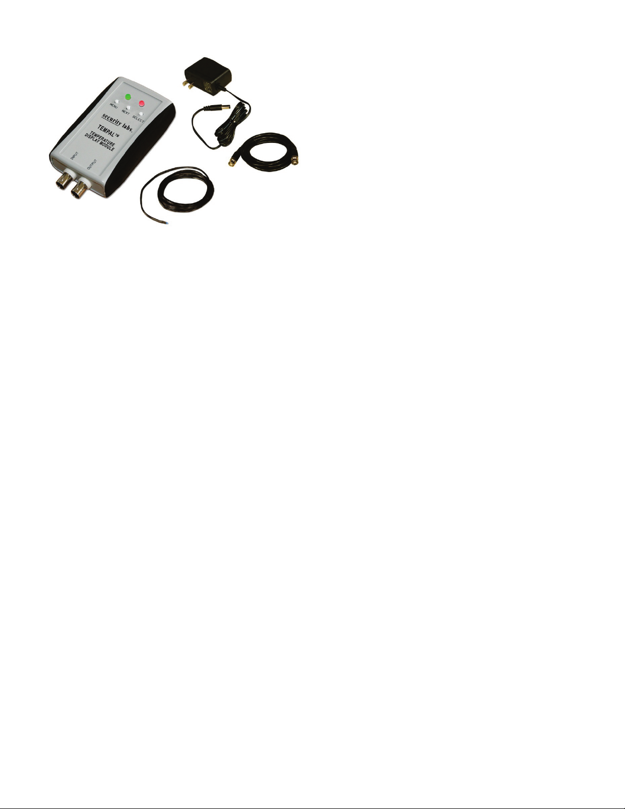
Items included with the TEMPALTM
UNPACKING
Confirm the following items are supplied with your
TEMPAL
TM
• TEMPALTM module
• 6’ temperature sensor probe
• Wall power adapter
• BNC video cable
• CD with manual
INSTALL ATION of the TEMPAL
TM
1) Plug a video camera, or other standard composite video source, into the BNC jack labeled INPUT.
2) Connect a monitor, or recording device, to the BNC jack labeled OUTPUT. A BNC to BNC cable is
supplied.
3) Confirm that the temperature sensor cable is connected to terminals TMP | TMP. They are not
polarized and can be installed either way. Due to the high impedance input on the temperature sensor
input terminal, up to 500’ of a wire extension cable can be added to the temp sensor.
4) Connect the 12VDC power supply (included) to the TEMPAL
5) View the temperature value on the monitor.
6) The back of the TEMPAL
TM
is designed for ease in wall mounting.
TM.
The green PWR LED will light.
OVERVIEW
The two main functions of the TEMPAL
TM
• Overlay a display of temperature on a CCTV camera or other composite video source.
• Provide an alarm condition when temperature is outside the set range.
Place the TEMPAL
TM
in an area in which temperature monitoring is desired. Place the extendable 6’
temperature sensor probe in an area within reach of the case location. If using to monitor ambient temperature
readings, make sure the sensor is not touching an object such as a panel, wall, or is in the path of an air flow
that could influence the temperature value. Ensure that the maximum temperature values for the module case
0
(160
F) and the temperature sensor (1800F) are not exceeded. If a higher temperature probe is desired,
contact the manufacturer. The TEMPAL
TM
can also be used to automatically alarm if the temperature occurs
outside the user programmed range set. There are 2 alarm triggers which can be enabled or disabled
individually: High Temperature / Low Temperature.
Page 3

SETTING UP THE TEMPALTM
Tap the MENU button to view programming screens. NOTE: If you leave the menu system on, after 30
seconds it will automatically return to the temperature display screen (Screen 5). The menu system will not
time out if the TEMPAL
TM
is in calibration mode.
Screen 1 - High Temp Value
[+] = increment value
[-] = decrement value
Press/Hold [-] and tap [+] to enable/disable this alarm trigger
Screen 2 - Low Temp Value
[+] = increment value
[-] = decrement value
Press/Hold [-] and tap [+] to enable/disable this alarm trigger
Screen 3 - Temperature Display Mode (deg F/deg C)
[+] = toggle value
[-] = not used
Screen 4 - Alarm Output Type (NO/NC)
[+] = toggle value
[-] = not used
An alarm condition will activate based on settings programmed in
screens 1 & 2. Values outside the range will activate alarm. The
‘ALARM’ LED on panel will turn RED during an temperature alarm
condition.
Page 4

ALARM CONTACTS
The alarm contacts on the TEMPAL
TM
are TTL level (5VDC, < 50mA ). The alarm contacts can be connected
directly to a panel or device that accepts a TTL level trigger input. If it is desired to trigger a 5VDC low power
device directly from the alarm terminal, set the output to N.O. When an alarm
is active, 5VDC will be present to power the device. The alarm contacts ARE
polarized so be sure to identify the ground terminal when connecting. When
connecting the alarm contacts to a DVR or other device, observe that the
TEMPAL
alarm type is programmed the same for both devices (N.O. or N.C.), the
TM
alarm output ‘ALM’ is connected to the other device’s alarm input.
TEMPAL
TM
ground ‘GND’ is connected to common or ground, and the
ALARM CONTACT OUTPUT
The alarm output can be programmed to be either NORMALLY OPEN (N.O.) or NORMALLY CLOSED (N.C.)
To set the alarm output type, PRESS MENU repeatedly until the OUTPUT screen appears. While viewing the
OUTPUT screen press [+] to toggle between N.O. and N.C. The setting is automatically saved.
When set to N.C., the alarm output will be +5VDC when active (alarm), & 0VDC when inactive.
When set to N.O., the alarm output will be 0VDC when active (alarm), & +5VDC when inactive.
Screen 5 - Display screen shows live temperature.
To move location of display:
[+] = move temp display vertically
[-] = move temp display horizontally
SCREENSAVER MODE
This feature causes the temperature display to move in random motion within the screen boundaries. To
enable screen save mode, hold the [–] button down and tap the [+] once. Release the [–] button. Wait 2-3
seconds and the display will start moving. To disable screen save mode, hold the [–] button down and tap the
[+] once. Release the [–] button. Follow instructions for “Screen 7” (above) if a new display location is desired.
TEMPERATURE CALIBRATION
The TEMPAL
gauge installed in a refrigerated room, a table top gauge, or other instrument. Before entering calibration mode,
ensure the TEMPAL
on the TEMPAL
TM
can be programmed to match readings of another temperature device, such as a commercial
TM
TM
sensor is in proximity to the temperature conditions the other device is reading. Power
and allow the sensors to adjust to the conditions. Once the TEMPALTM temperature value
has leveled, enter the calibration mode.
Page 5

CALIBRATION MODE
Remove the power plug from the TEMPAL
button and re-connect power. Release MENU. A ‘SET TMP’ will appear on
screen. Press the [+] or [–] buttons to select the desired temperature level. To
save the calibration and return to normal mode, cycle power by removing the
power plug and re-inserting it. The unit is now calibrated to the new levels.
REMOVE CALIBRATION SETTINGS
Remove the power plug from the TEMPAL
the [–] button. Previous calibration settings are now erased from memory.
TEMPAL
Questions? Contact Security Labs Technical Support at 1-800-774-0284
TM
Suggested Uses:
• Monitor refrigerated rooms for temperature fluctuations or power loss
• Track and send alerts for loss of heat in vacation homes
• Monitor temperature in sensitive areas such as archival storage facilities
• Monitor farm incubators and nurseries
• Connect to an equipped DVR to view display worldwide over a mobile device or PC. Receive email or
text alerts when TEMPAL
and alerts.
TM
alarms. An internet /email capable DVR is required for remote monitoring
TM
. PRESS and HOLD the [-] button and re-connect power. Release
TM
. PRESS and HOLD the MENU
Page 6

TEMPALTM Technical Specifications
Min environmental temperature for included probe 00 F (-180 C)
0
Max environmental temperature for included probe 180
Max case environmental temperature 160
F (820 C)
0
F (710 C)
Power supply 12VDC (210mA consumption)
Video input source Requires standard composite 75 ohm, 1v p-p video
Menu Three button nested programming, 7 screens
Alarm output Selectable Normally Open (NO) or Normally Closed (NC)
Alarm contacts TTL (0-5V/ 50mA max)
Temperature alarm Any value outside the user programmed range
Calibration Adjustable temperature value for matching to another device
Screen display Temperature can be positioned anywhere on screen
Screensaver mode Mode enables display to move around screen randomly
Temperature probe 6’ 22 gauge sensor wire included
Case size 2.6” W x 4.3” D x 1.1” H
Limited Product Warranty
TEMPAL
Should this product prove to be defective in material or workmanship under normal usage, we will provide
without charge to the consumer, parts and/or labor necessary to remedy the defect for the period of ONE YEAR
from the date of purchase. The warranty period commences on the date that the product is purchased by the
consumer. Any implied warranty is also limited to the duration above.
THIS WARRANTY DOES NOT COVER THE FOLLOWING: FLUCTUATIONS IN THE POWER SOURCE OR
LIGHTNING-RELATED DAMAGE; ATTACHED OR UNATTACHED ACCESSORIES; COSMETIC PARTS SUCH AS
KNOBS AND ACCESS DOORS; CABINET DAMAGE, INCLUDING DAMAGE IN TRANSIT; ACCIDENTAL DAMAGE;
MISUSE; ABUSE; UNAUTHORIZED PARTS USAGE OR REPAIRS; RECEPTION PROBLEMS DUE TO INADEQUATE
SIGNAL; UNAUTHORIZED INTERNAL CONTROL OF ADJUSTMENTS; INSTALLATION; ADJUSTMENT OF
CONSUMER CONTROLS; EXCEEDING THE MAXIMUM OR MINIMUM RATED LIMITATIONS OF THE PRODUCT AS
OUTLINED; OR ANY USE OF THE PRODUCT OTHER THAN THAT SPECIFICALLY PRESCRIBED IN THE OWNER'S
MANUAL. THIS WARRANTY APPLIES TO PRODUCT SOLD AS NEW AND NOT REMANUFACTURED,
RECERTIFIED, OR B STOCK PRODUCTS.
THE MANUFACTURER’S OBLIGATION UNDER THIS WARRANTY SHALL BE TO REPLACE SUCH PARTS AND
PROVIDE LABOR AS STATED. THE MANUFACTURER WILL NOT BE LIABLE FOR ANY LOSSES OR
INCONVENIENCES DIRECT OR INDIRECT, OR CONSEQUENTIAL PROPERTY DAMAGES.
To obtain warranty service, the consumer must provide the product, along with evidence that will positively identify the
date that the product was purchased, from an authorized product representative, dealer, retailer, or distributor. Prior to
shipment, a RETURN AUTHORIZATION must be obtained; this will assist us in efficient service on your unit, and possibly
avoid shipment if the adjustment can be made over the phone. If shipment is made, the cost for postage, insurance and
shipping of the product is the responsibility of the owner.
TM
: ONE YEAR PARTS AND LABOR
To obtain a warranty return authorization number, contact our Customer Service at:
Security Labs Customer Support 1-800-774-0284 www.security-labs.com
 Loading...