

Security Labs H.264,16 Channel,8 Channel,4 Channel Owner's Manual
6
H.264 Dual Stream /
Pentaplex DVR Series
4/8/16 Channel
Owner’ s M anual
15540 Herriman Blvd. Noblesville, IN 46060 - www.security-labs.com
Customer Support 1-800-774-0284
VER.:1.0, P/N: 264-6 DMS/MBR
Copyright – MMX
2
This symbol is inte nded to alert the user to th e presence of unprot ected “Dangero us voltage"
within the product' s enclosure that may be strong enough to cause a ri sk of elect ric shock.
This symbol is intended to alert the user to the presence of important operating and
maintenance (servicing) instructions in the literature accompanying the appliance.
WARNING -
TO REDUCE THE RISK OF FIRE OR ELECTRIC SHOCK, DO NOT EXPOSE THIS
APPLIANCE TO RAIN OR MOISTURE.
NOTE: This equipment has been tested and found to comply with the limits for a class digital device,
pursuant to part 15 of the FCC Rules. These limits are designed to provide rea sonable protection against
harmful interference when the equipment is operated in a commercial environment. This equipment
generates, uses, and can radiate radio frequency energy and, if not installed and used in accordance with the
instruction manual, may cause harmful interference to radio communications. Operation of this equipment in a
residential area is lik ely to cause harm ful interference in which case the user will be required to cor rect the
interference at their o wn expens e.
Disposal of Old Electrical & Electronic Equipment (Applicable in the European
Union and other European countries with separate collection systems)
This symbol on the pro duct or on its p ackaging in dicates that th is product sha ll not be treat ed as household
waste. Instead it shall be handed over to the applicable collection point for the recycling of electrical and
electronic equipm ent. By ensuring this product is disposed of correctly, you will help prevent potent ial
negative consequences for the environment and human healt h, which could otherwise be c aused by
inappropriate waste h andling of this product. The rec ycling of materials will help to conserve natural
resources. For mor e detailed inform ation about rec ycling of this produc t, please contact your loc al city
office, your household waste disposal service or the shop where you purchased the product.
• Make sure to disconnect or switch power off before you install the DVR.
• There is the danger of an electric shock if the DVR is opened by an unqualified service
engineer or installer.
• Avoid using the DVR outside of the reference temperature and humidity indicated in the
specification.
• Avoid exposing the DVR to violent movement or vibration.
• Do not use or store the DVR in direct sunlight or near to any source of heat.
• Do not place any objects near the vent holes in the case used for air circulation.
• Always use the DVR in a well ventilated location to prevent overheating.
• There is risk of an explosion if the backup battery is replaced by an incorrect type.

3
TABLE OF CONTENTS
Chapter 1 Installation ……………………………… ……………………………
1.1 System Configuration - 16 Channel ..…………………..…………
1.2 System Configuration - 8 Channel ……………………………..….
1.3 System Configuration - 4 Channel …………………………..…….
1.4 Hard Disk Installation …………………………………………..…...
Chapter 2 QUICK REFERENCE - MENUS and INDICATORS ……………..
2.1 On-Screen Functions and Status Indicators ……………..……….
2.2 Main Menu ………………………………………………..………….
2.3 Playback Mode …………………………………..…….…………….
2.4 PTZ Mode …………………………………………..………………..
CHAPTER 3 OPERATION AND MENU SETUP ……………………………..
3.1 Log On Screen ………………………………………………..……..
3.2 Record Setup ………………………………………………..……….
3.3 Event Setup ………………………………………………..………...
3.4 Schedule Setup ……………………………………………..……….
3.5 Camera / Audio Setup ………………………………..……………..
3.6 Account Setup ………………………………………...……………...
3.7 Network Setup ………………………...………………………………
3.8 PTZ & RS-485 Setup …………………………………………………
3.9 System Setup …………………………………………………………
3.10 Utility Setup ………………………………………………………….
3.11 Diagnostic …………………………………………….………………
Chapter 4 SEARCH & BACKUP…………………….…………….…….……….
4.1 Search Setup ……………………………….………….………………
4.2 Backup Setup ………………………………………….………………
4.3 Remote (Network) Backup ……………………………..…………….
4.4 Converting an IRF backup file to an AVI …………….……………...
SPECIFICATIONS ………………………………………………..……………….
5
5
5
6
6
9
9
12
13
14
15
15
17
19
23
25
27
29
41
42
49
50
51
51
54
56
56
59

4
FEATURES
H.264 compression ideal for saving HDD space
Pentaplex Operation: Live display, record, backup, playback and network access
simultaneously
16 Channel Model : Up to (3) SATA 1TB HDDs or (2) SATA 1TB HDDs plus DVDR
4 or 8 Channel Models: Up to (2) SATA 1TB HDDs or (1) SATA 1TB HDD plus DVDR
Port on back panel for additional eSATA external hard drive
Dual streaming for faster network transmission
Built-in VGA output up to 1024x768 resolution
16MB of pre-alarm storage per event (approximately 10 seconds before event
happens)
22 x 15 (330 point) grid video motion detection per channel
Nine criteria items to search for events per channel
Individual setup of resolution, frame rate and video quality for each channel
Picture-in-picture monitoring and 2X to 8X digital zoom display
Control Methods: Front panel, USB mouse, IR remote, & PC client viewer
Intuitive GUI for easy configuration and menu driven operation
Still image snapshot
AVI converter with time stamp
Pan / Tilt / Zoom camera control
Two USB ports (for mouse usage and backup).
Data backup via: USB devices, network, and DVD-RW (optional on some models)
E-mail notification & event trigger for motion d etec ti o n, al ar m, and video loss
Supports network operation with Internet Explorer
Multi-language OSD
3G/ GPRS mobile phone monit ori ng
5
Chapter 1 INSTALLATION
Note: Please be sure NTSC/PAL switch near the video output jack is set properly for your
location before powering up the unit. NTSC is the standard for all of North America.
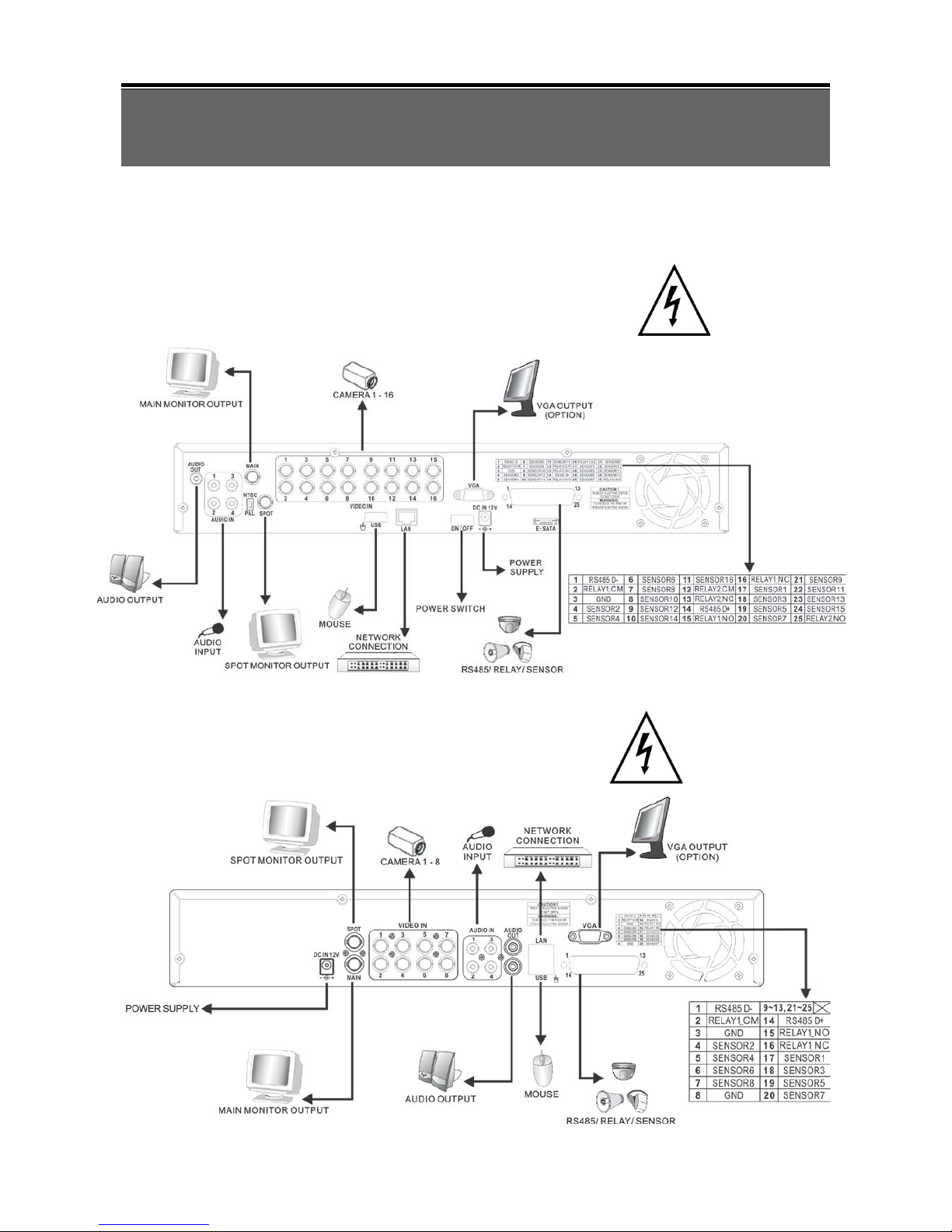
1.1 System Configuration – 16CH
1.2 System Configuration – 8CH

6
1.3 System Configuration – 4CH
1.4 Hard Disk Install ation
Your unit comes with a hard drive already installed. Four and eight channel models can
have a second hard drive or a DVD writer installed. The sixteen channel model may have
two additional hard drives, or an additional hard drive plus a DVD writer installed. Up to
ONE TERABYTE size hard drives can be used. For best performance, please use the
same size and model of hard drive in each location. Always format the hard drive(s) after
installing a new one (see section 3.10, Initialization). Please be sure you have saved any
data you wish to keep from an existing drive. Formatting will erase all data.
4 / 8 Channel Layout 16 Channel Layout
7
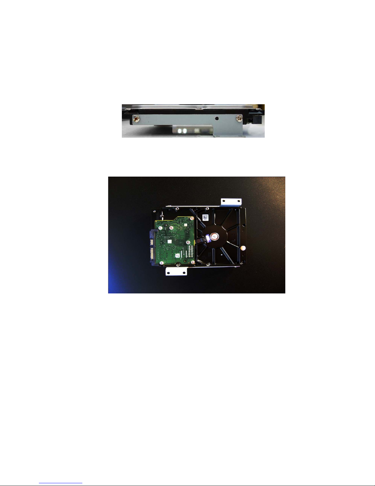
DISCONNECT THE POWER FROM THE DVR BEFORE REMOVING THE COVER
.
Mount the H DD br acke ts in a r ev erse fashion on both sides of the HDD (Figure 1 and 2)
similar to the drive already installed in your unit.
Figure 1
Figure 2
The red SATA data cables are wired the same at both ends. Please observe the right
angle alignment key before inserting the cable into the hard drive or main PC board. The
SATA connectors on the main PC board are in order from front to back. Connect your first
drive closest to the front panel, then in order towards the back. Connecting the drives out
of order will not harm the drives, but makes them easier to locate should they have the
same model ID number. ID numbers of the drives are read electronically and displayed in
the Utilities Menu. Please refer to figure 3 for more layout and connection information.
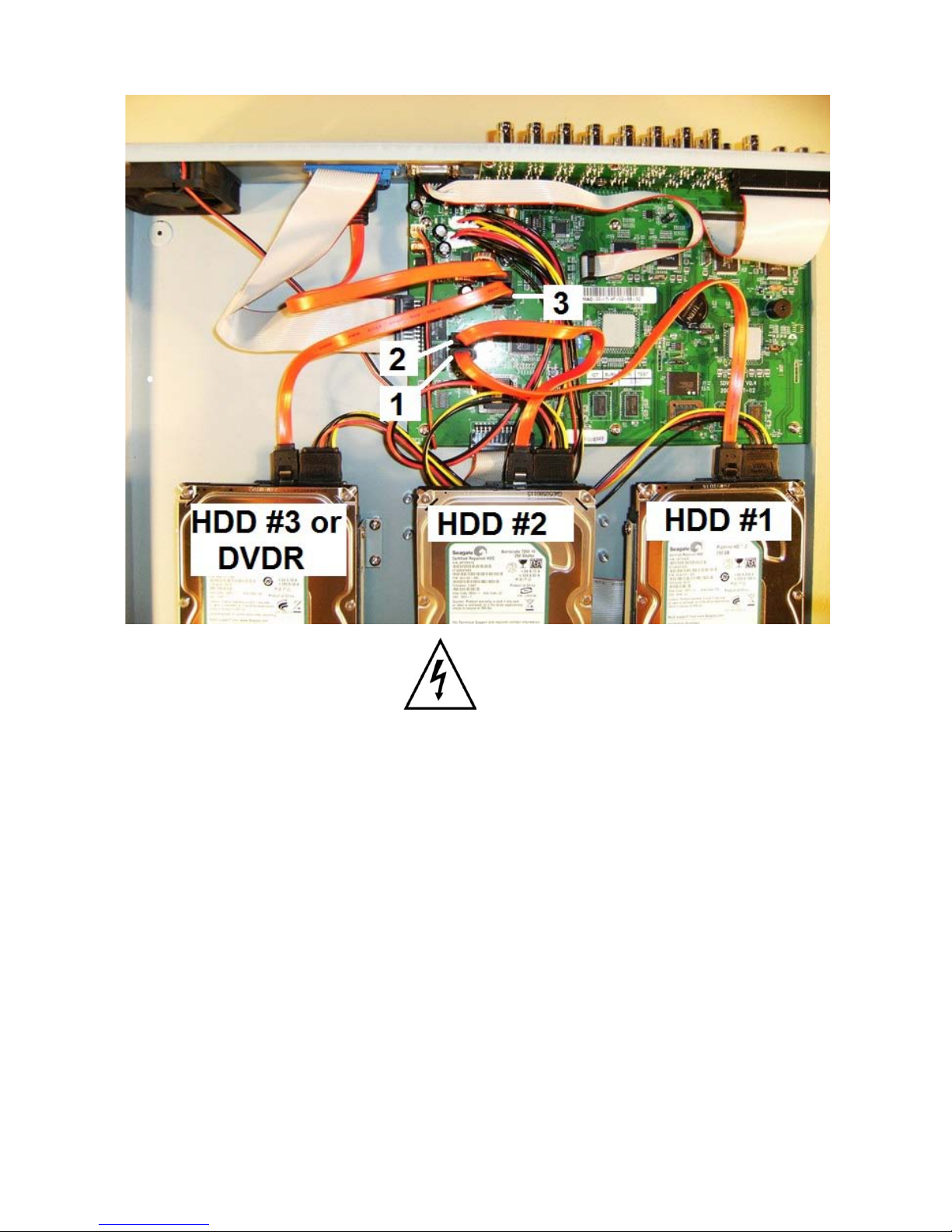
8
Figure 3
The eSATA jack on the back panel allows you to connect a fourth drive if desired for a total 4
terabyte capacity (4 x 1TB = 4TB).
Note: Please be sure NTSC/PAL switch near the video output jack is set properly for your
location before powering up the unit. NTSC is the standard for all of North America.
9
Chapter 2 QUICK REFERENCE
MENUS and INDICATORS
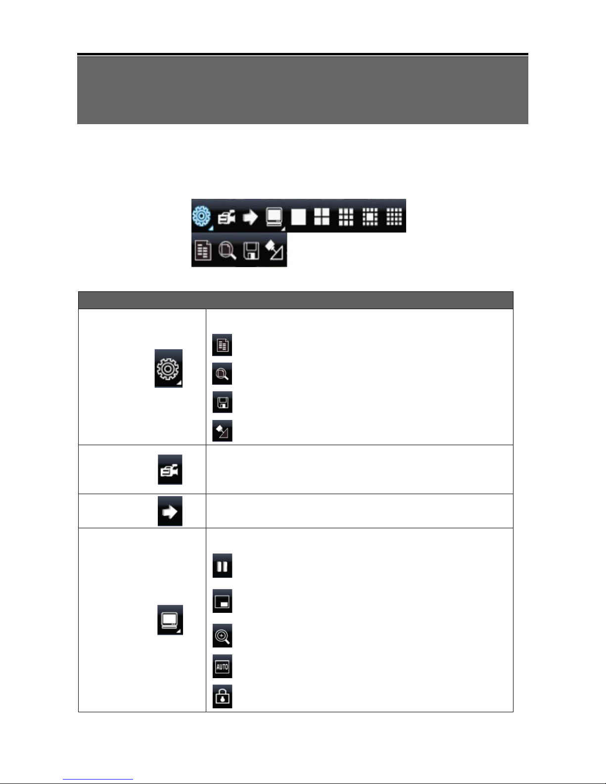
2.1 On Screen Functions
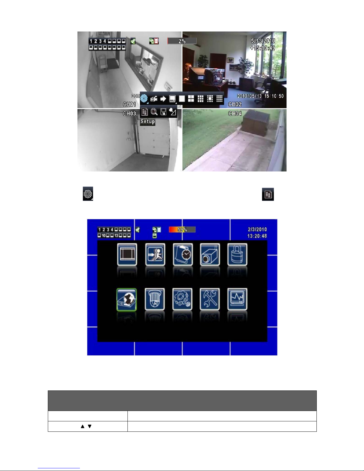
Right clicking on the screen with the mouse or using the MENU button on the front panel
will activate the NAVIGATION BAR.
Graphic Icons
Resting the cursor on the SETUP icon will bring up four (Main Menu/
Search/ Backup/ PTZ) menu icons.
MAIN MENU.
SEARCH SETUP.
BACKUP.
PTZ CONTROL.
Turns the record function ON/OFF (View Normal frame rate must be
active see Section 3.2.1).
PLAYBACK – Initiates the play function and displays more controls.
Resting the cursor on the Display Setup icon will bring up five more
(PAUSE/ PIP/ ZOOM/ AUTO SEQ/ LOCK) display icons.
PAUSE will free ze li ve v id e o
Picture-in-Picture displays two cameras. Right click on the
channel number above the smaller view to change the camera
shown.
ZOOM, 2X to 8X digital zoom
AUTO-sequence will rotate through each camera in full screen.
Log Off / Activates password access required for next user
10
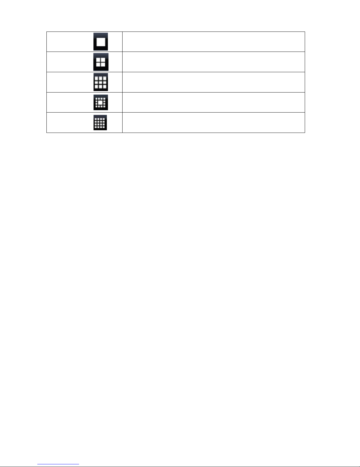
Full screen display, multiple clicking to switch channels
Quad display.
9CH Split-screen display available on 8 and16CH DVRs.
13CH Split-screen disp lay available on16CH DVR.
16CH Split-screen disp lay available on 16CH DVR.
11
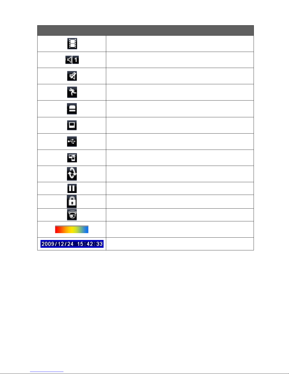
On-Screen Status Indicators
Recording is ON
Number represents the current selected LIVE audio channel (available to
8/ 16CH DVR and option to 4CH DVR).
Live Audio is OFF
Motion detected
Alarm sensor triggered
Video loss detected
USB device detected
DVR is connected to the Internet
Auto Sequence is ON
Pause mode is ON
Front Panel Control LOCK is ON
PTZ controls are ON
Shows the current hard disk space used (up to 99%). Will remain at
99% during OVERWRITE (continuous recording) mode.
Time / Date bar shown on a playback file
99%
12
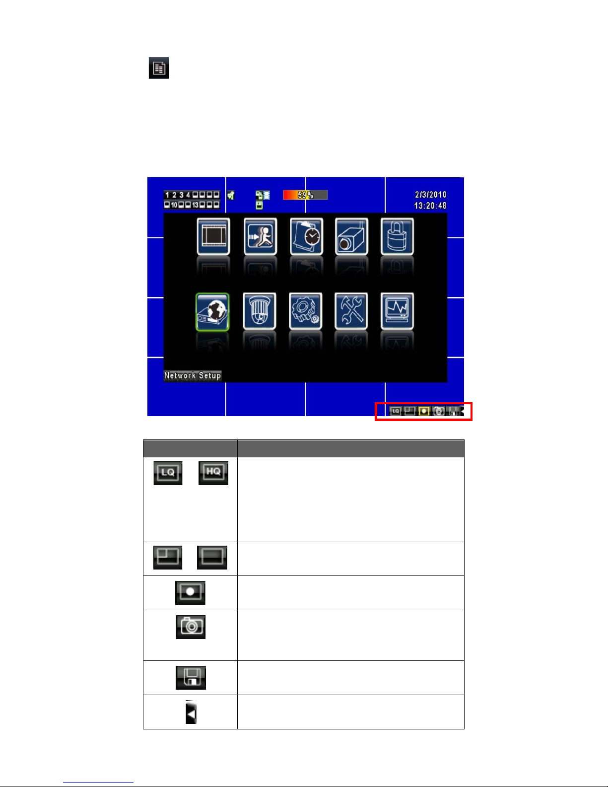
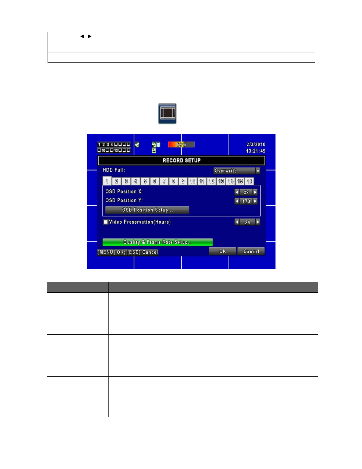
2.2 MAIN MENU
The majority of settings for your DVR are accessed via the MAIN MENU. Adjustment
of the settings can be done locally or via the internet. Each sub-menu activated by the
icons below are described in greater detail in Chapter 3. When accessing the MAIN
MENU via a local network or internet connection, an additional row of icons is displayed
in the bottom right corner of the screen. They are described below.
Icon Description
/
Changes your live PC view from:
Low Video Quality (LQ) to
High Video Quality (HQ)
Note: High may run slower depending on
your internet connection.
/
Selects Standard Screen / Maximum
Screen.
Records live video to your PC.
Takes a snapshot and sends it to the
Snapshot folder, located inside the
DVRemote Folder.
Confirm or change your Record and
Snapshot storage pat h folder settings.
Open or Close the tool bar
13
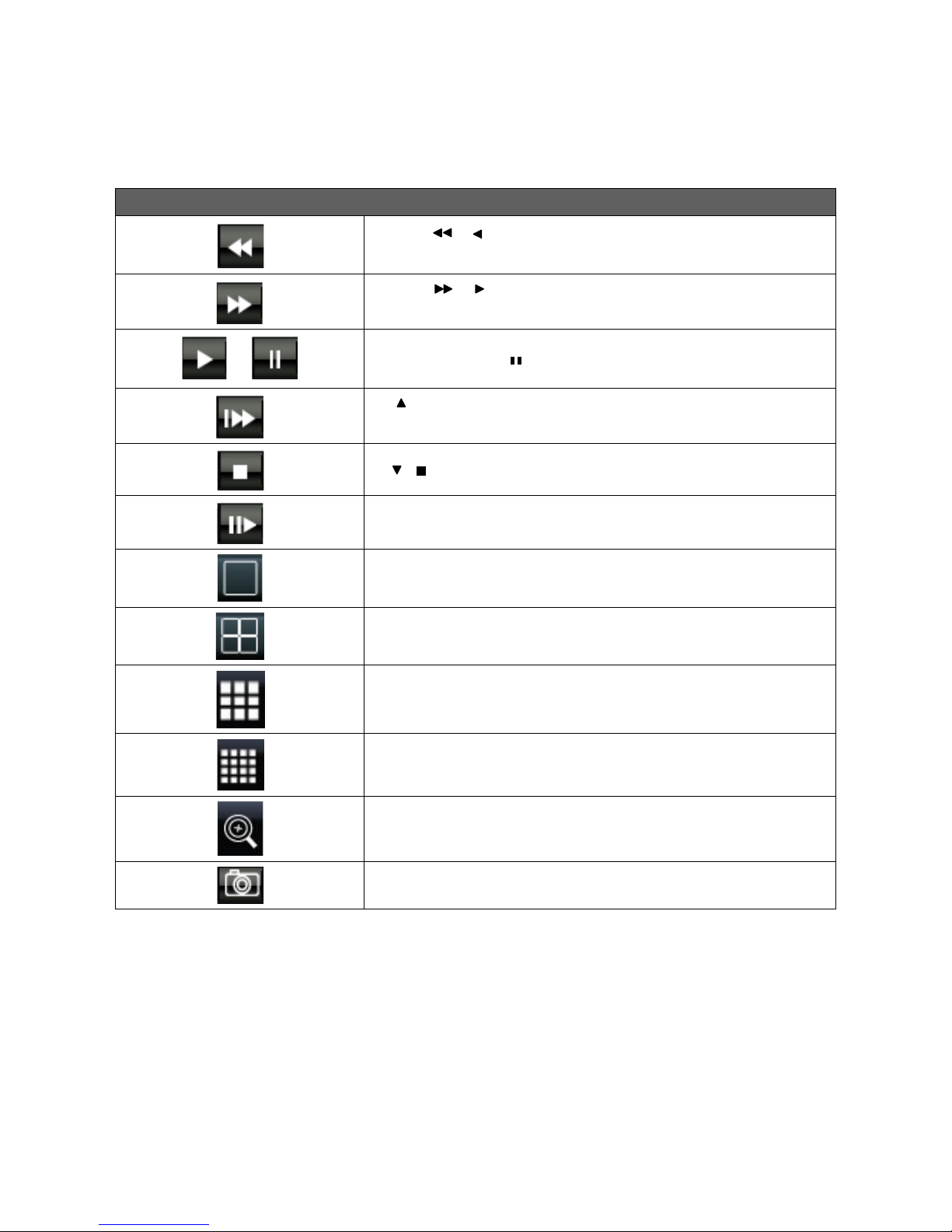
2.3 Playback Mode
Playback – On Screen Function Icons
Press「 / 」button for Fast Rewind
Speeds : 2x, 4x, 8x, 16x, 32x, 64x
Press「 / 」button for Fast Forward
Speeds : 2x, 4x, 8x, 16x, 32x, 64x
/
Press「PLAY」/ 「 」buttons for Play and to Pause Playback
「 / SLOW」Slow Motion Playback
Speeds : 1/2x, 1/4x, 1/8x, 1/16x
「 / 」Stop Playback
Playback frame by frame of selected channel
Full screen display
Quad display
9CH Split-screen display (available only on 8/ 16CH model)
16CH Split-screen disp lay (available only on 16CH model)
Digital Zoom into playback video
Sends a snapshot image to your USB Flash Drive (if connected).
14
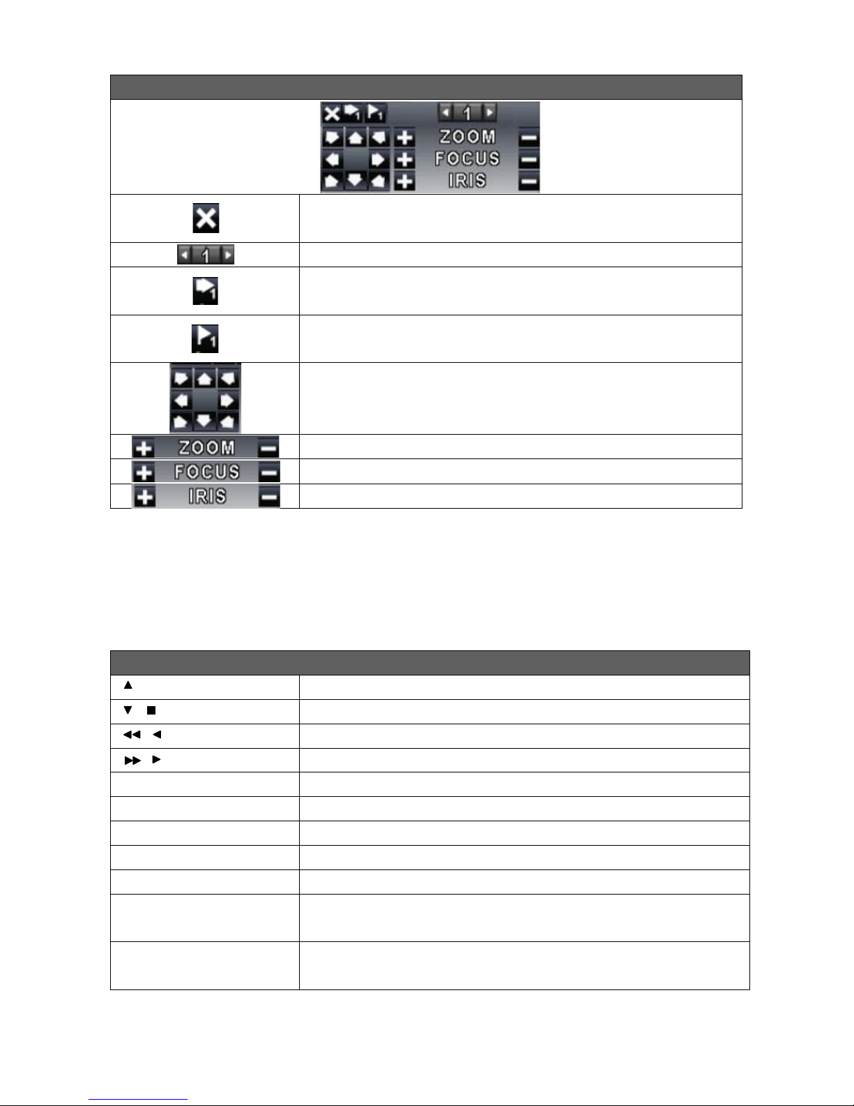
PTZ – On Screen Controls
Exit PTZ Mode
Preset number (1~64)
Go to preset number selected
Set current PTZ location at preset number selected.
Directional movement arrows
Camera ZOOM + (Close Up), ZOOM – (Wide Angle View)
Manual focus control for camera
Manual iris adjustment for camera (if available)
2.4 PTZ Mode – Commands Using the IR Remote
Control
PTZ – Control with Hand Held IR Remote Control
/ SLOW
Tilt up.
/
Tilt down.
/
Pan to the left.
/
Pan to the right.
ZOOM +
Zoom in (close up)
ZOOM -
Zoom out (wide angle)
FOCUS + & FOCUS -
Camera focus
IRIS +
Camera iris-open.
IRIS -
Camera iris-close.
PRESET + NUMBER
To save a preset location
Press PRESET and a number key.
PLAY + NUMBER
To go to a preset location
Press PLAY and a number key.
15
Chapter 3 OPERATION and MENU SETUP
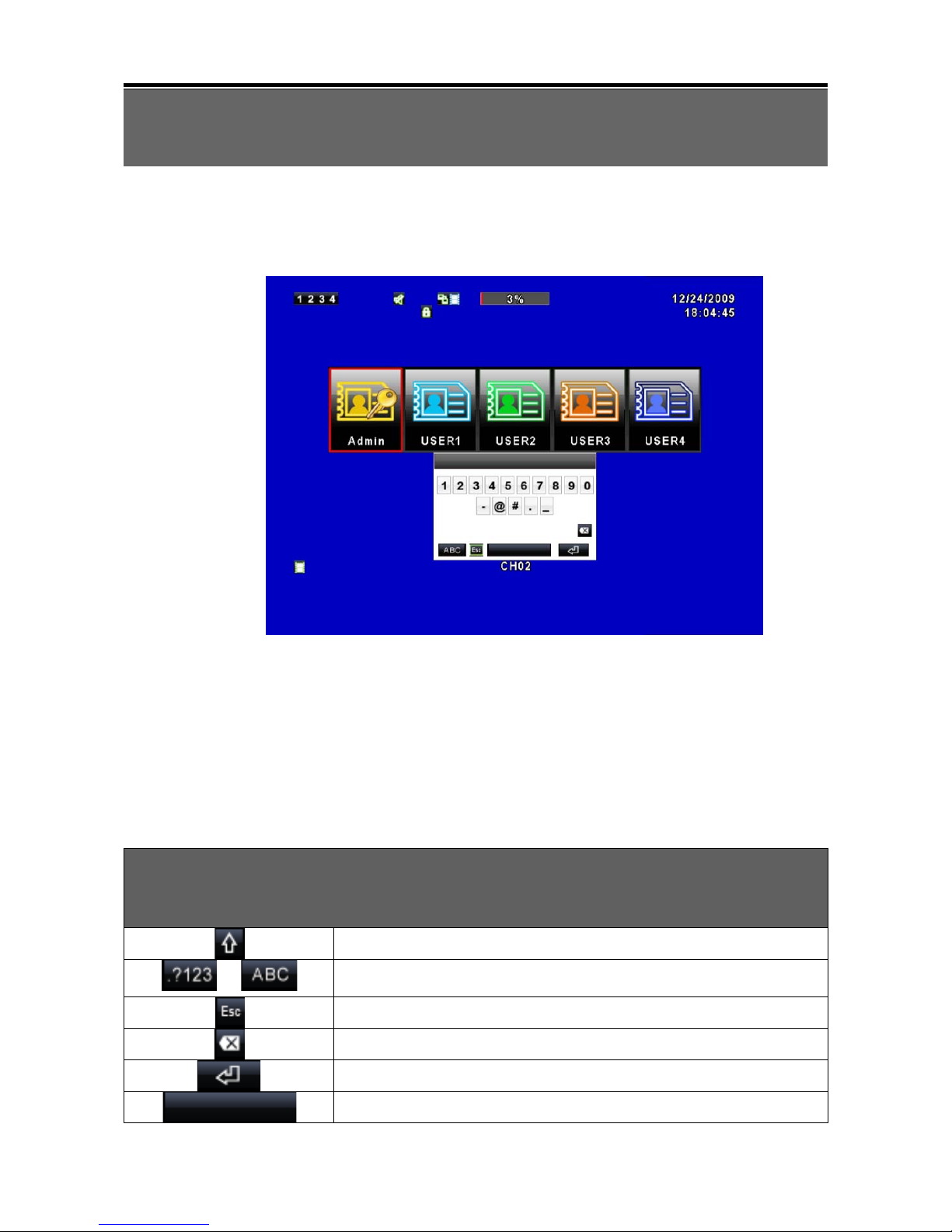
3.1 Log On Screen
If access to your MAIN MEN U i s pr ot ected, using y our mo use, left click on the Admin
icon to bring up the pa ssword entry screen, le ft click o n each nu mera l or letter of your
password, then click on the “Enter” arrow in the bottom right corner
. The default
password of the ad mi n i st rat or is “123456”. Four a ddi ti o nal users can b e ad ded with
up to six levels of access each. Please refer to “3.6 Account Setup” for more
information.
The navigation arrows and ENTER button on your remote control may
be used instead of the mouse.
Password Entry Screen
Switch between capital and small letters.
/
Switch between numbers and letters.
Press to cancel or choose another login account.
Delete the last character.
Enter (after login name com pleted)
Space key
16
Right click on the screen to activate the Navigation Bar. Hover your mouse pointer over the
Setup icon to display a second row of icons. Click on Main Menu to display the
screen below.
Use your mouse to click on each menu icon, or use the IR remote control or the front panel
controls as described below.
Navigating menus with the IR Remote Control or Front Panel Controls
(Click MENU button to ente r )
MENU
Activates the Navigation Bar
Scrolls the list of items
17
Change values in selected item
ESC
Press to cancel or exit setup
ENTER
Activates the selected menu
3.2 Record Setup
Item Description
HDD FULL
Select STOP to stop recording when the hard drive(s) ar e full, or OVERWRITE to
enable continuous recording.
[Stop]
:
Stop Recording when HDD(s) is full
[Overwrite]
:
Start to overwrite beginning with the oldest data on the HDD, and
continue to record.
OSD Position
Setup
A time/date stamp is added to the video f or each channel being recorded. The
position of the stamp can be adjusted for each channel
individually to avoid
blocking any important items. Selecting a channel number on this screen, and then
OSD Position Setup, allows you to preview where the time/date stamp will be
recorded.
OSD Position X
Sets the Horizontal placement from 0 to 456, use the arrows on the box or left click
on the center of the box to activate a numeric keypad.
OSD Position Y
Sets the Vertical placement from 0 to 456, use the arrows on the box or left click on
the center of the box to activate a numeric keypad.
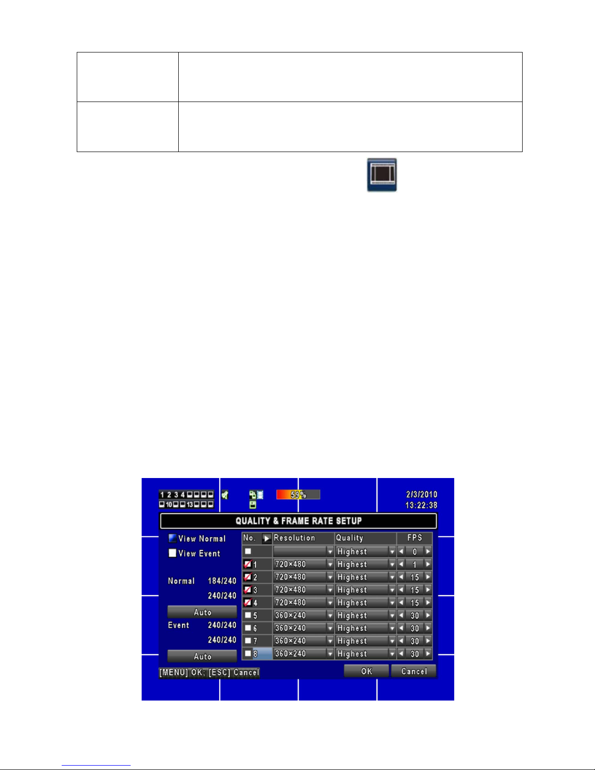
18
Video
Preservation
(Hours)
Click box to activate. Information stored on the HDD is additionally protected from
overwrite for this specified length of time.
Quality &
Frame Rate
Setup
Allows individual adjustment of both items per channel as described below.
3.2.1 Quality & Frame Rate Setup
Increased recording time on a hard drive can be achieved by decreasing the frames
per second (FPS) recorded. Continuously recording (Normal) at a slower rate, and
event recording at a faster rate is a suggested method of operating your DVR.
Recording a static image of an empty office area is a waste of hard drive space. By
using video motion detection, or alarm recording triggered by an external device such
as a PIR or door switch, a faster frame rate can be then used to record activity as it
happens. Reducing the quality or resolution of the images being recorded (smaller
file size) is another method of extending the overall record time on a hard drive. Five
Quality settings are available on your DVR: Highest, High, Normal, Basic, and Below
Basic. Three resolution selections are also available: 720 x 480, 720 x 240, and 360
x 240. Lower quality can be used when larger objects are being recorded, or finer
details within an image are not especially important. There is no best setting for all
installations. Experiment with the resolution, quality, and FPS settings to see what is
best for your situation. The rule of thumb is to use the best possible settings (720 x
480, Highest, and a faster frame rate) that still gives you the total number of days
stored on your hard drive that you require.
19
Item Description
View Normal / View Event
Selects between Normal (continuous) and Event (alarm or motion)
record settings per channel
No.
Check/ Uncheck the box will enable/ disable record mode of all channels
shown on the page, or each channel can be controlled individually.
Resolution
360 x 240 Basic, 720 x 240 Better, 720 x 480 Best
Quality
Choose from Belo w Basic / Basic/ Normal/ High/ Highest.
FPS
Recording frame rate (1~30).
Normal Auto
Automatically calculates the maximum FPS for each active channel after
you choose a resolution setting in the Normal recording mode.
Event Auto
Automatically calculates the maximum FPS for each active channel after
you choose a resolution setting in the Event recording mode.
The Normal and Event frame rate calculators on t he le ft si de o f th e a bov e menu are there
to quickly add the total frames per second r equeste d via the resolution s ettings, FPS, an d
cameras selected. Up to 240 frames are available for each group of 8 channels that
your DVR model may contain (240 for 4 and 8 channel models, and 240 + 240 for the 16
channel model). If a fast recording speed (high FPS) is needed with many cameras,
you can select a lower resolution to accomplish this. If the highest resolution setting is
needed on most of your cameras, then you may need to select a lower FPS (recording
speed) for some cam eras. The numb ers on the c alcul ator s w ill turn r ed if y our de mands
are too high. Lowering the resolution or FPS on some cameras will correct this situation.
Clicking on the Auto button will quickly adjust the overall settings for you.
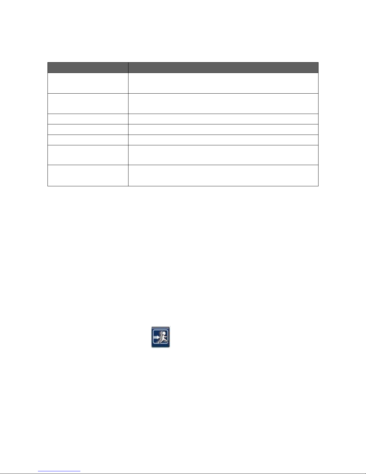
3.3 Event Setup
As mentioned above, video motion detection and alarm / sensor recording are a great way
to conserve hard drive space, limit recordings to meaningful activities, and create a means
to quickly find recordings that are pertinent. The video motion detection feature built into
this DVR is designed to be one of the best in the industry with 11 sensitivity settings and a
selectable detection grid of 330 small squares (22 x 15) per camera. Pinpoint accuracy is
made possible with this type of grid system.
 Loading...