

Security-Center TV7218, TV7219 Installation Instructions Manual
IR network domecamera
Installation instructions
TV7218
TV7219

2
Preface
Dear Customer,
Thank you for purchasing this IR dome network camera of the DIGI-LAN series from Security Center. You made the
right decision in choosing this state-of-the-art technology,
which complies with the current standards of domestic and European regulations. The CE has been proven and all
related certifications are available from the manufacturer upon request.
To maintain this status and to guarantee safe operation, it is your obligation to observe these operating instructions!
In the event of questions, please contact your local specialist dealer.
This IR dome network camera is used for object surveillance. The recorded video signals are transmitted to a
computer digitally via the connected network. The computer software permits simultaneous recording of up to 16
connected video signals. Data storage is subject to local national data-protection guidelines. Via the Internet
Explorer, you have worldwide access to installed cameras (password-protected).
Precautions
The IR dome network camera and connected components must be kept free of moisture (cellars and similar
surroundings are to be strictly avoided). Use of this product for other than the described purpose may lead to
damage of the product. Other hazards such as short-circuiting, fire, electric shock, etc., are also possible. The
equipment is designed for operation using a Class 2 12V DC transformer. No part of the product may be changed
or modified in any way. Connection to the public power network is subject to country-specific regulations. Please be
aware of applicable regulations in advance.
To avoid fire and injury, please observe the
following:
Securely fasten the device at a dry location in the
building.
Ensure sufficient air circulation.
Do not expose the device to temperatures less than
0°C or more than 50°C.
The device is designed for indoor use only.
Humidity must not exceed 90% (non-condensed).
Ensure that the voltage is disconnected when
performing work on the device.
Please observe the following regulations to ensure
trouble-free operation of your device.
The IR dome network camera is supplied by a 12V
DC transformer.
The transformer should be connected to the 230V
AC building mains by means of a separate,
electrically protected line.
Connection work to the building mains is subject
to country-specific regulations.
General:
Improper or careless installation work may lead to faults and poor image quality. Therefore please read the
instructions very carefully and follow the installation instructions for lines and components precisely.
The manufacturer reserves the right to make technical modifications at any time.

3
Before using this product
The use of surveillance equipment may be forbidden by law in some countries. This IR dome network camera is not
only high-quality web camera but can also be used as part of a flexible surveillance system. Before using this
equipment, make sure that all your surveillance activities are completely legal.
Before installation, check the product for completeness (page 5: Scope of delivery). Read the installation instructions
before installing the IR dome network camera. Read the “Installation” chapter carefully and follow the instructions
contained in it to avoid damage caused by faulty assembly or incorrect installation. This will ensure that the
equipment goes into operation correctly for the intended purpose.
Appendixes A and B (Troubleshooting, FAQ) contain possible solutions to problems occurring during installation
and configuration.
The installation instructions describe different usage scenarios of the IR dome network camera. The chapter “URL
Commands of the IR dome network camera” is intended to help professional users design their own homepage or
integrate the camera with web servers.
Sections marked with contain special hints and advice for the user. Ignoring this advice can result
in damage to the equipment or injury.

4
Contents
Preface………………………………………………………………………………………………………………….. 2
Precautions……………………………………………………………………………………………………………. 2
Before using this product……………………………………………………………………………………………… 3
Contents……………………………………………………………………………………………………..…………..4
Scope of delivery……………………………………………………………………………………………………….. 5
Hardware installation…………………………………………………………………………………………………... 6
First access to IR dome network camera………………………………………..…………………………………….. 8
Setting the IP address……………………………………………………………….……………………..…. 8
Access to the network camera via the Internet Explorer………………………….………………………………...… 13
Defining a password to prevent unauthorised access………………………………………………………. 13
Changing the administrator password………………………………………………………………….…… 14
Installing the plug-in………………………………………………….…….………………………………... 15
Basic user functions……………………………………………………………….…................................ 16
Main window and Camera view…….………………………………………….…….…….……… 16
Client setting……………………………………………………………………….……………..… 18
Adminstrator settings………………………………………………………………………………………… 20
Configuration / video…………………………………………………………..……………...…… 20
Protecting the IR dome network camera with a password…………………………………..….… 21
Opening accounts for new users…………………………………………………………...……... 21
More flexible options for the viewer………………………………………………………..………. 22
Allow “demo” account to view……………………………………………….…………... 22
Format of a multimedia website………………………………………..……….……….. 22
Alarm inputs/outputs………………………………………….………………………………….… 24
Time-controlled surveillance…………………………………….….……………………….…….. 26
Integrated video sensor…………………………………………..………………………………... 27
Updating the software version……………………………………….…………………………….. 28
System configuration…………………………………………………………………………………..…………….… 29
System………….………………………………………………………………………..…….……. 29
Security………………………………………………………………………………..…………….. 30
Network………………………………………………………………………………..…..…..……. 30
General…………………………….……………………………………….…………..…. 30
HTTP…………………………………………………………….…….…………………… 30
Data flow…………………………………………………………………………….…….. 30
DDNS and UPnP settings…………………………………………………………………..….……. 31
Mail & FTP………………………………………………………………………………………..…. 32
Video……….………………………………………………………………..…………….….…….. 34
Picture settings………………………………………………….………………..……….. 35
Camera settings……………………………………………….………………………….. 35
Audio-Einstellungen………………………………………………………………………………… 36
Motion sensor…………..…………………………………………………….............................. 37
Application………………………………………………………………………………………….. 38
Weekly schedule…………………………………………………….…………………….. 38
Event reaction……………………………………………………….…………………….. 38
Sequencing………………………………………………………………………………… 38
Viewing the log file ……………………………………………………………………….………... 39
Viewing parameters……………………………………………………………………….…….….. 39
Factory settings……………………………………………………………………………...…..….. 39
Appendix………………………………………………………………………………………………….……..…….. 40
A. Troubleshooting……………………………………………………………………..……..……. 41
B. Frequently asked questions (FAQ)………………………………………………...………..…… 42
C. URL commands of the IR dome network camera……………………………….…………..…. 43
D. Technical data………………………………………………………………………..………….. 57
5
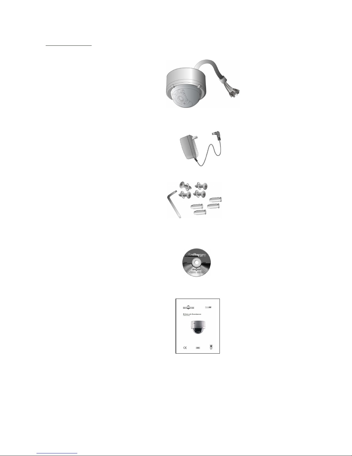
Scope of delivery
IR dome network camera
TV7200 / 7201
Transformer
Screw kit
Software CD
Installation instructions (on CD)
6
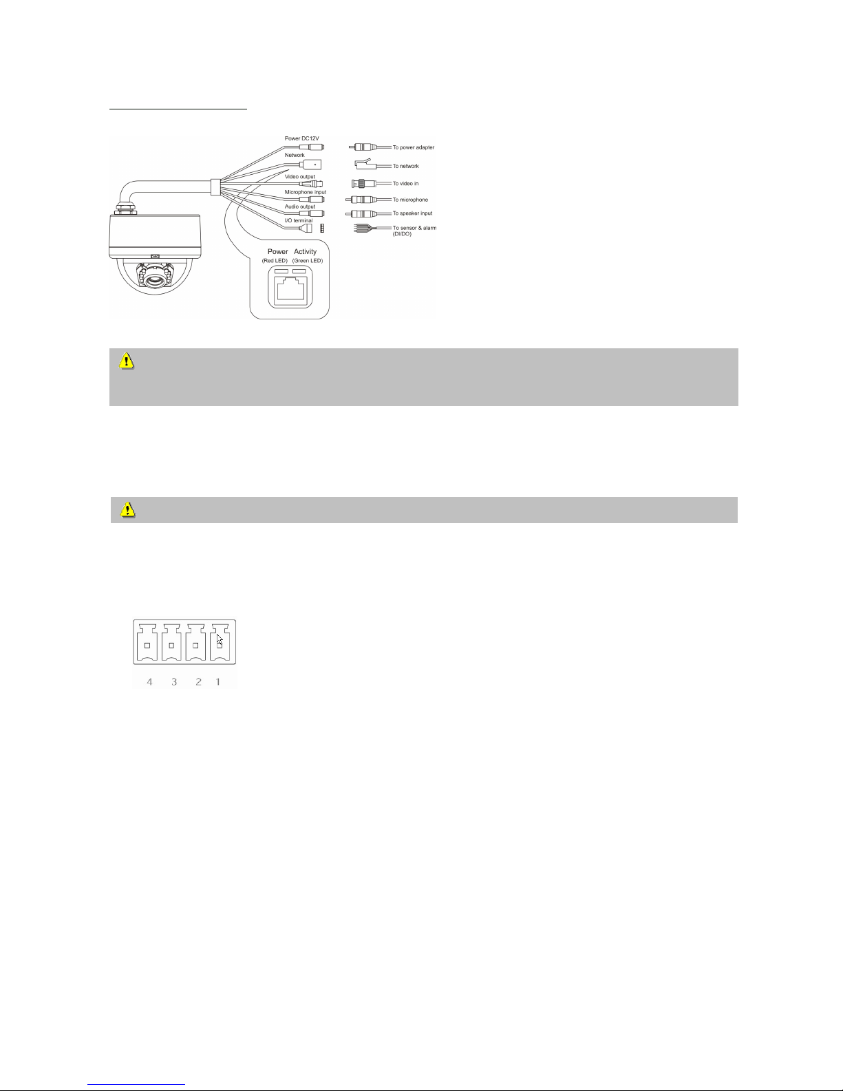
Hardware installation
When the camera is switched on, it runs a self-test, and the Power/Activity LEDs flashes green and red. If this selftest completes successfully, the LED flashes green and the IR dome network camera is ready for you to enter an IP
address. After you enter an IP address, the green LED flashes once every second. If the self-test is not successful, the
red LED flashes several times. For troubleshooting hints, see Appendix A.
The IR dome network camera is equipped via an I/O terminal block with a digital input and a relay for device
control. At Pin 1 and Pin 2, an external digital input signal can be processed, whereby the voltage state is
monitored in the start phase at LOW. The output (Pin 3 and Pin 4) can be used for switching external devices on
and off.
Make sure that all accessories and articles listed
above are present in the scope of delivery.
Depending on application, an Ethernet cable may
be required. This Ethernet cable must meet the
specifications of UTP Category 5 (CAT 5) and
must not be longer than 100 meters.
To prevent the risk of electric shock, first connect the socket of the transformer to the security
network camera before inserting the transformer into the mains socket.
Consult your dealer for the correct installation of peripheral devices.
1 DI- INPUT (output status of DI is low)
2 DI+ INPUT (max. 50mA, 12V DC)
3 RELAY OUTPUT (output status open)
4 RELAY OUTPUT (max. 1A, 24V DC)
7
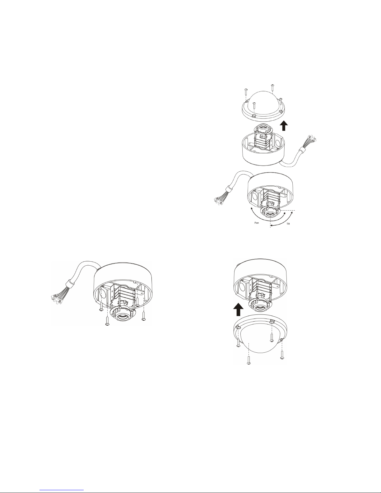
Installation of the IR dome network camera
Proceed as follows when installing the camera.
1. Select a suitable place on the ceilling of the room where you would like to mount the camera.
2. Removing the housing cover of the camera by unscrewing the
cover screws with the supplied wrench.
3. Chose the cable lead-through you want (side or housing
bottom). Close the unused opening with the metal plug.
4. Connect the network cable to the network connector. Connect
all other necessary cables to the camera (e.g. test monitor to
the video output).
5. Connect a 12V power supply to the power input of the camera.
6. Hold the camera at the location where you want to mount
it. Check the orientation and angle of the camera.
7. Change the tilt of the camera module if necessary.
8. Select the desired image framing at the lens by setting the
zoom (only TV7219). Optimise the sharpness by adjusting
the focus at the lens (only TV7219).
9. Mount the camera to the wanted place and screw the
dome cover back to the camera.
8
First access to IR dome network camera
Setting the IP address
To set the IP address of the camera:
Use a network cable to connect the IR dome network camera to your computer network.
(The simplest way is to connect the IR dome network camera direct to your PC using a cross-link cable.)
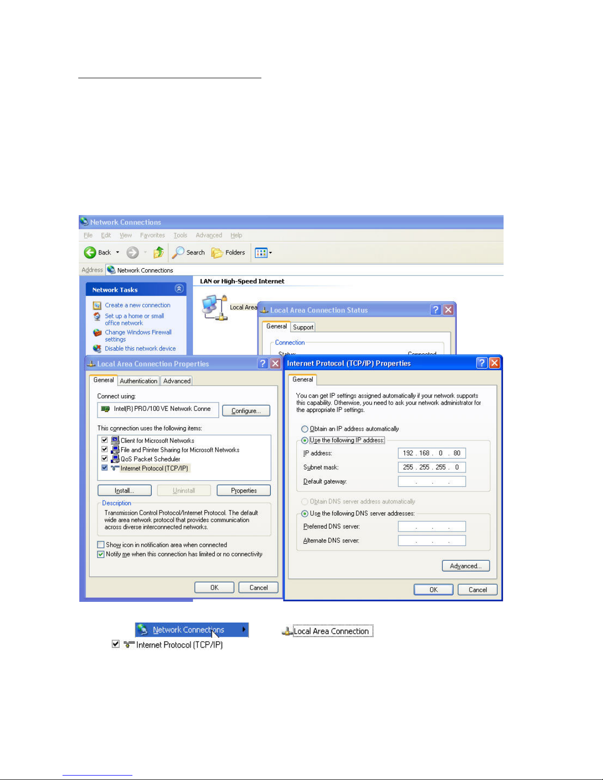
If your PC is not yet integrated into a network, you first have to configure it for the network application. Do this by
opening the Properties page for your network.
(This also applies if the camera is connected to the PC via a hub or switch.)
1. Click
, select and open the Properties page of the
.
2. Enter a fixed IP address and subnet mask
(e.g.: 192.168.0.80 and as subnet mask 255.255.255.0).
9
- The network connection of your PC is now configured.
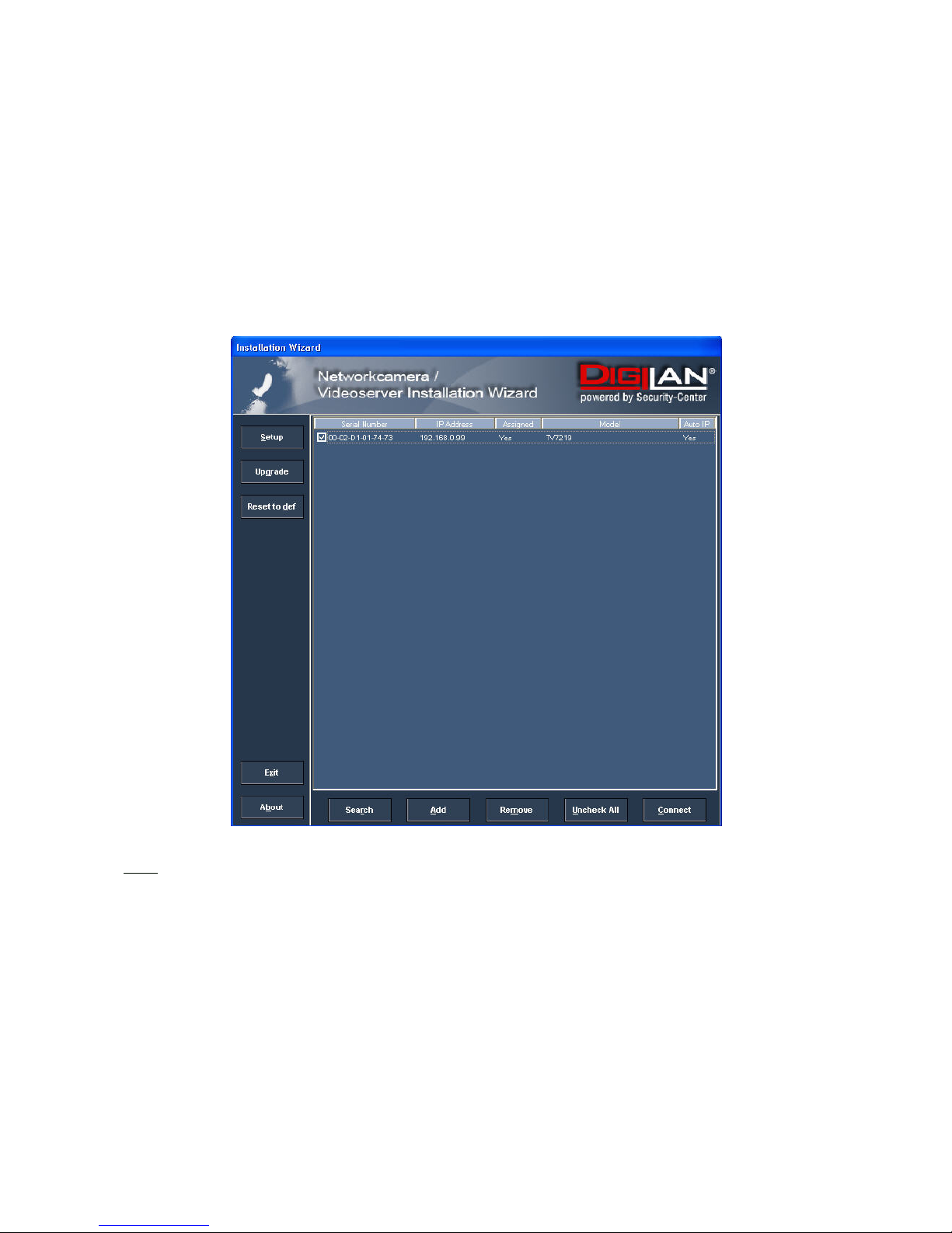
3. Now start the Installation Wizard from the software CD supplied.
4. Follow the installation instructions of the Installation Wizard.
5. If installation is successful, start the program under Programs/Installation Wizard.
6. Following the program start, the Installation Wizard automatically searches for a connected network
camera.
7. If no camera is found in the first search, click “Search” for a new search.
Note:
The IP addresses shown in the “Current IP Address” field reflect those on the local network. They may be from the
DHCP server. If there is no DHCP server, the camera will try to find a free IP address (this takes from 15 seconds to
3 minutes, depending on the LAN status). The method of finding an IP address is seeking from 192.168.0.99, to
192.168.0.254. If any of the address inside this range is free, the network camera will be assigned to this IP
address, and its subnet mask would be 255.255.255.0. If none of the addresses is free, the network camera will try
the range from 192.168.0.2 to 192.168.0.98. After an IP address is assigned to the camera, the “Activity” status
LED blinks.
Note: If no camera is found via the manual search, change the network settings of your PC as described in the
instructions.
10
8. Select one of the camera models found.
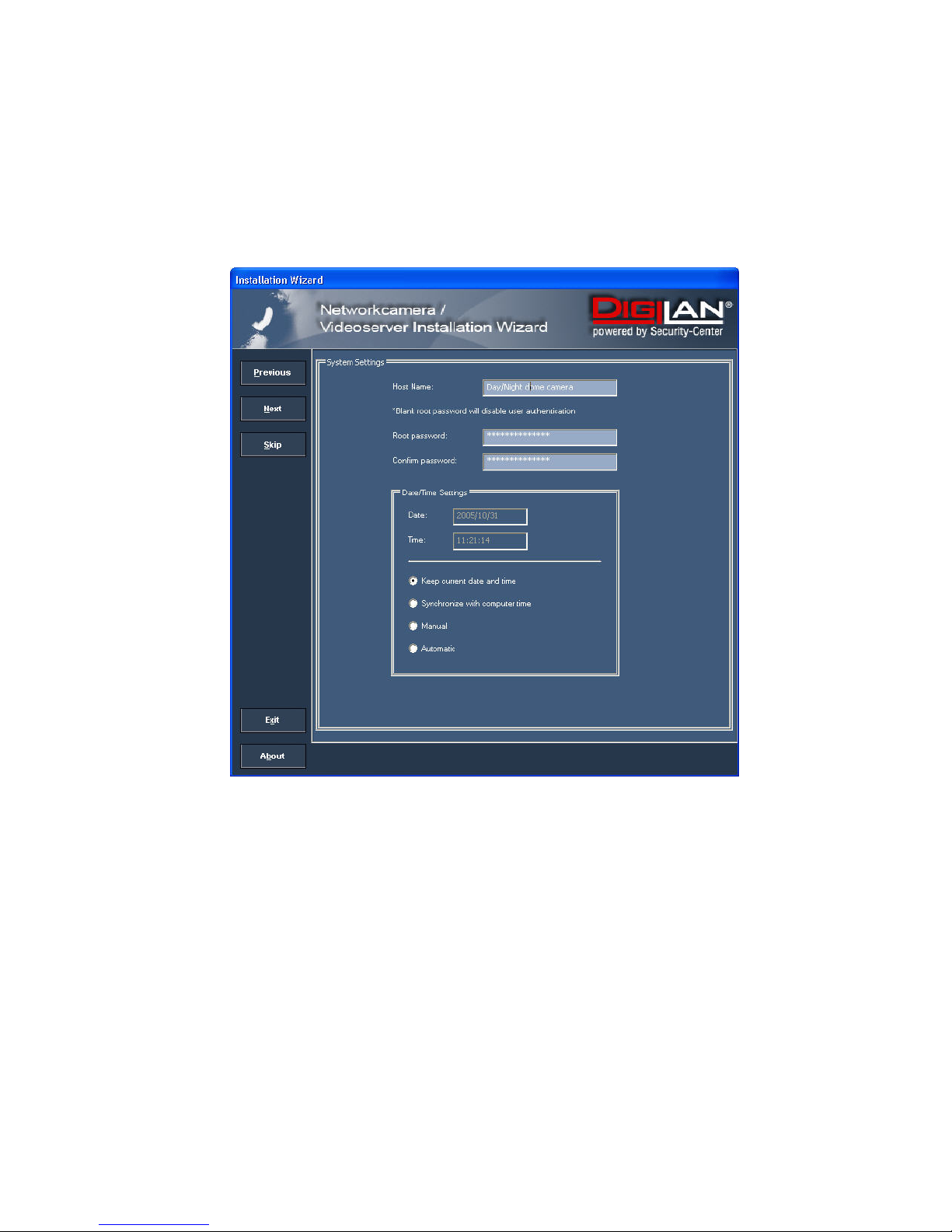
9. Click “Setup” to enter camera setup mode. If a password is required, use the device serial number
(no spaces, uppercase letters only). You can change the hostname, the administrator password and the
date/time settings of the camera. If you cannot access the settings, check the IP addresses of your
network adapter and your network camera. The IP addresses must be in the same subnet area. If
necessary, change the IP address of the network adapter (page 7).
11
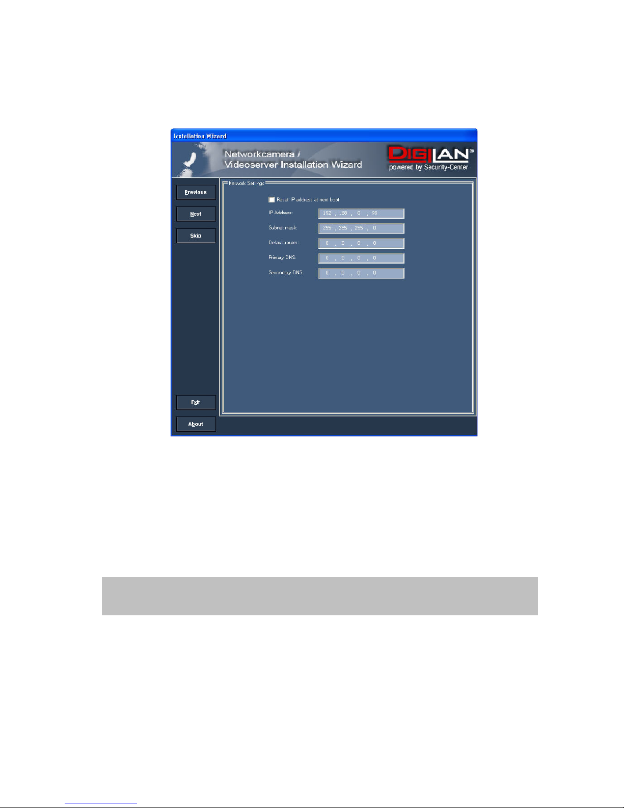
10. Now click “Next” to change the IP address of your network camera.
If you use a router in your network, enter this IP address (gateway) in the Default Router field.
11. If you disable “Reset IP address at next boot”, you do not have to reassign the IP address of this camera
following a power failure. Otherwise, you have to reassign the IP address after every camera restart.
12. Click “Next”.
13. Follow the instructions on the screen to save or change your settings.
The Installation Wizard is finished. Click “Previous” to change your settings. Click “Apply” to save your
input and transfer it to the selected device.
12
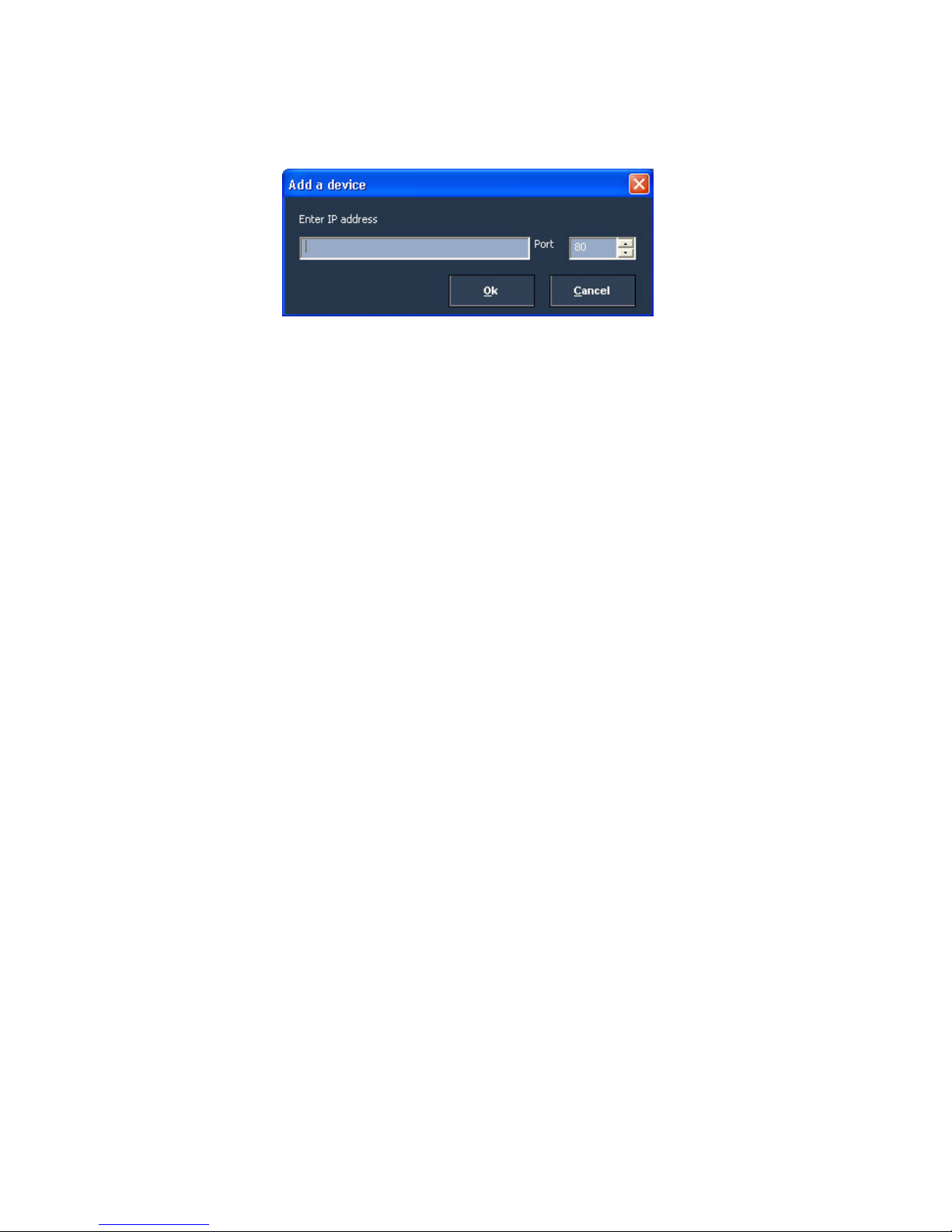
14. Click “Add” to add a network camera direct via the IP address or its domain name. You need this only if the
camera was not found by the automatic search.
15. Click “Remove” or “Uncheck all” to remove one or all network cameras from the menu.
16. Click “Connect” to set up a link to the selected network camera via the Internet Explorer.
13
Access to the network camera via the Internet Explorer
Defining a password to prevent unauthorised access
For security reasons, the administrator should define a new password immediately. After the new administrator
password is stored, the IR dome network camera asks for the user name and password every time it is accessed.
The administrator can define up to twenty (20) user accounts. Every user has access to the IR dome network
camera, but not to the system configuration. Some system-critical functions are reserved for the administrator, such
as system configuration, user administration and upgrading software programs. The administrator’s user name is
always root and cannot be changed. Following a password change, the browser displays an authentication
window and asks for the new password. After changing the password, you cannot restore the original
administrator password. Your only option is to reset all default factory settings/parameters.
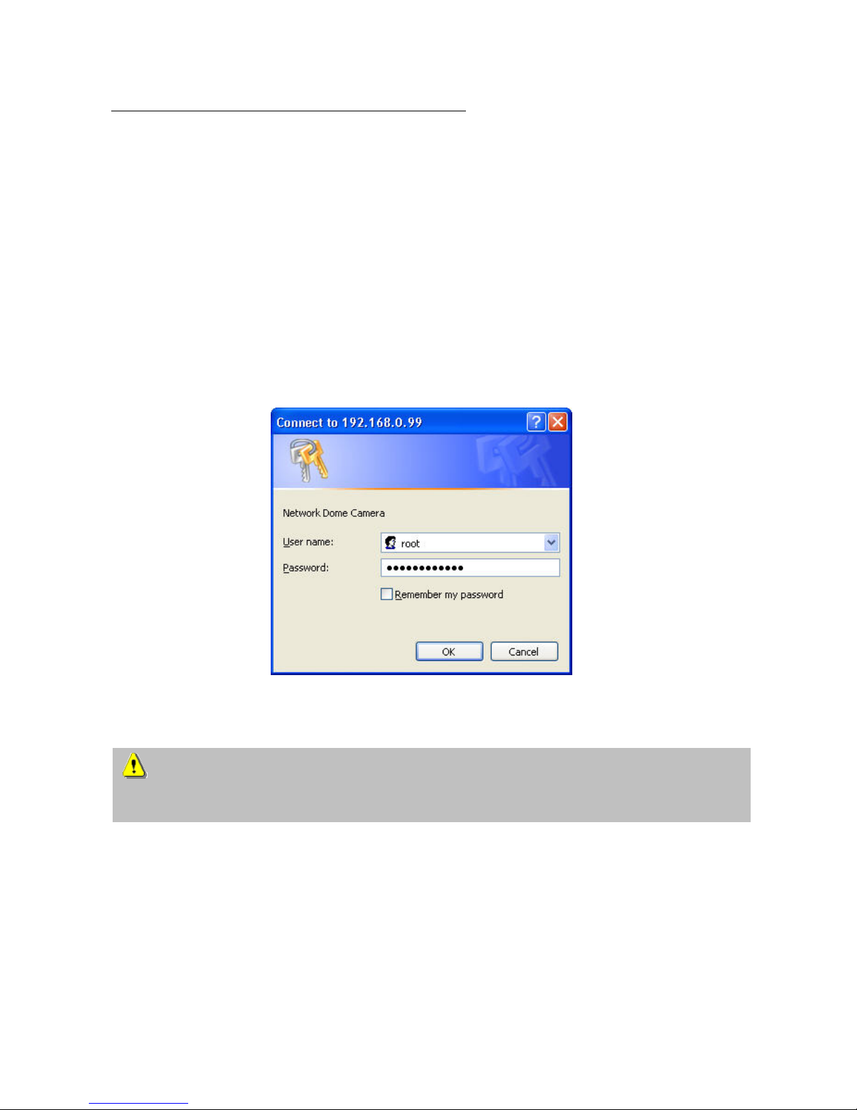
To enter the password:
Open the Internet Explorer and enter the IP address of the camera
(e.g.: <http://192.168.0.99>).
You are prompted for authentication:
Î You are now connected with the IR dome network camera and can see a video stream.
Note: It may happen that your PC’s security settings prevent a video stream. You can change the security
settings to a lower level under “Tools/Internet Options/Security”. Make sure you enable Active
X
Control
Elements and Downloads.
14
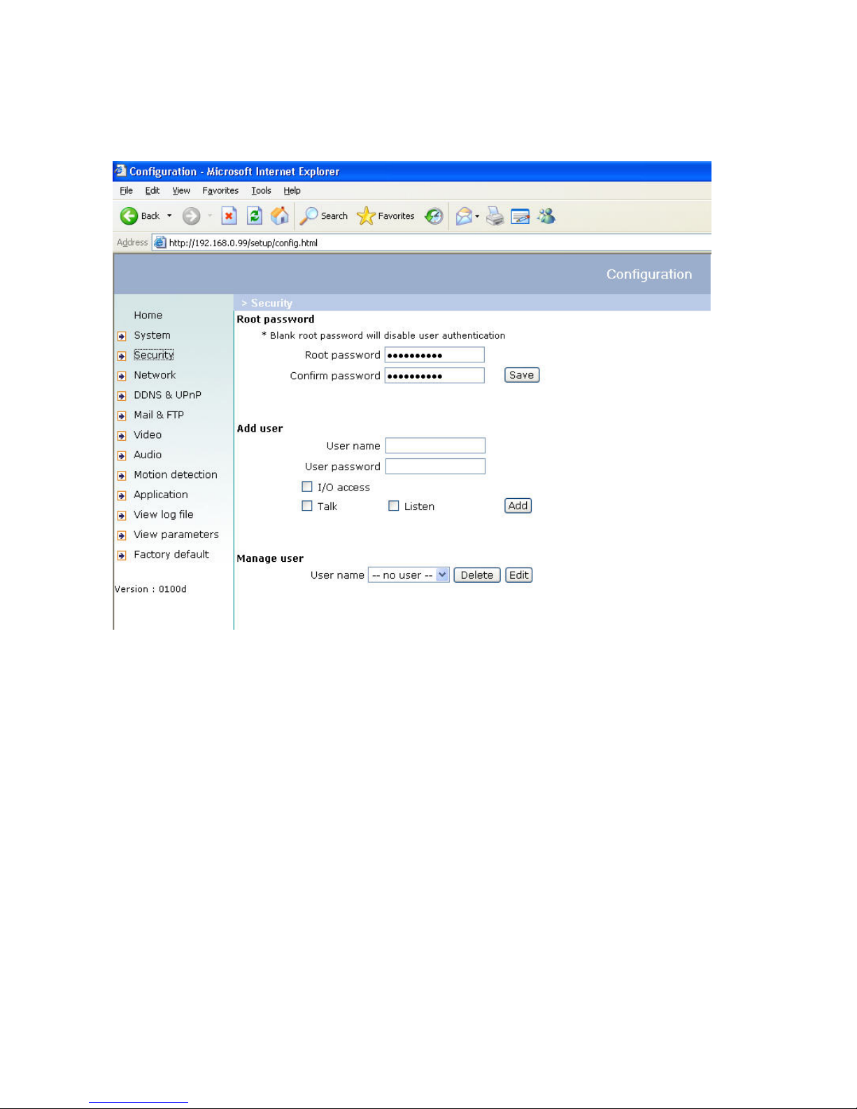
Changing the administrator password
Click “Configuration” and then “Security”.
Under “Root password”, enter the administrator password and confirm it under “Confirm password”.
Click “Save”.
The new administrator password is saved.
Click “HOME” in the column on the left to exit configuration.
15
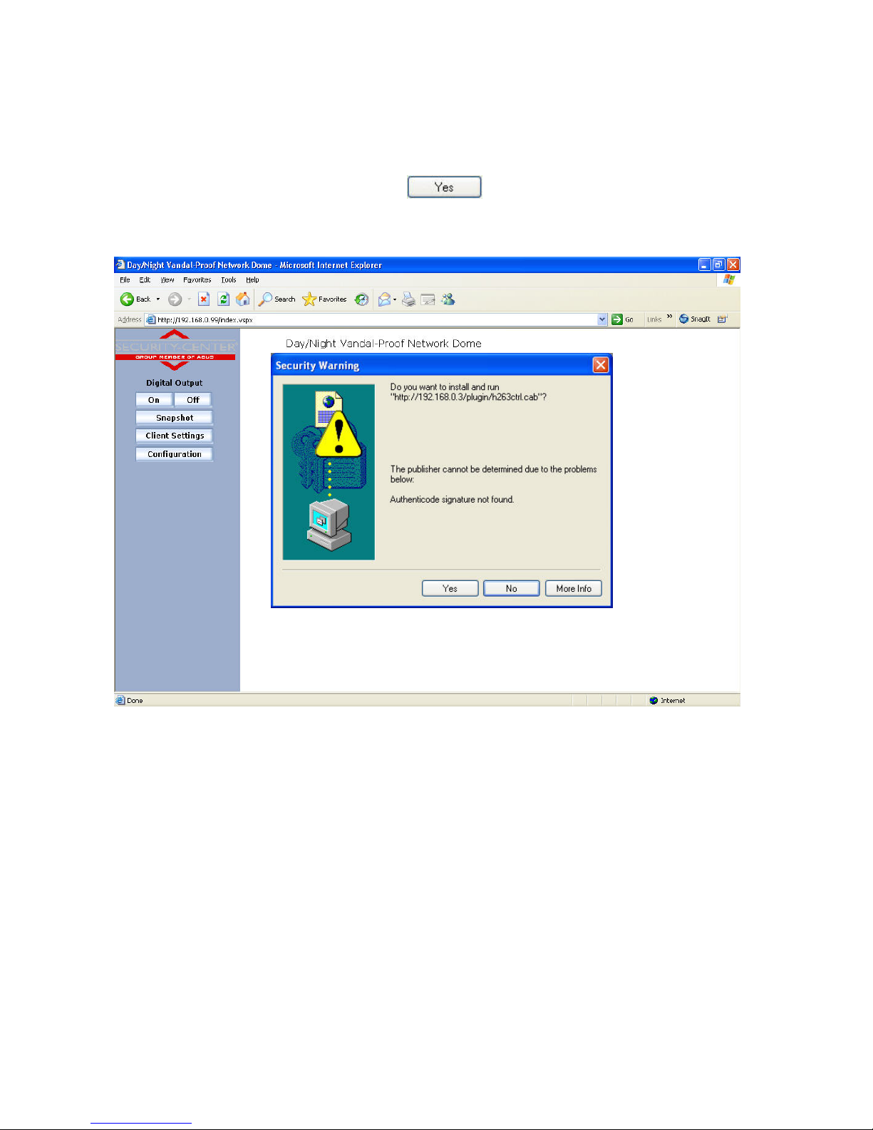
Installing the plug-in
When you first access the IR dome network camera under Windows, the web browser may ask for the installation of
a new plug-in for the IR dome network camera. This query depends on the Internet security settings of your PC. If
the highest security level is set, the PC will refuse any installation and any attempt at execution. This plug-in is used
for video display in the browser. To continue, click
. If the web browser prevents continuation of the
installation, open the Internet security settings and reduce the security level or consult the IT administrator or
network administrator.
16
Basic user functions
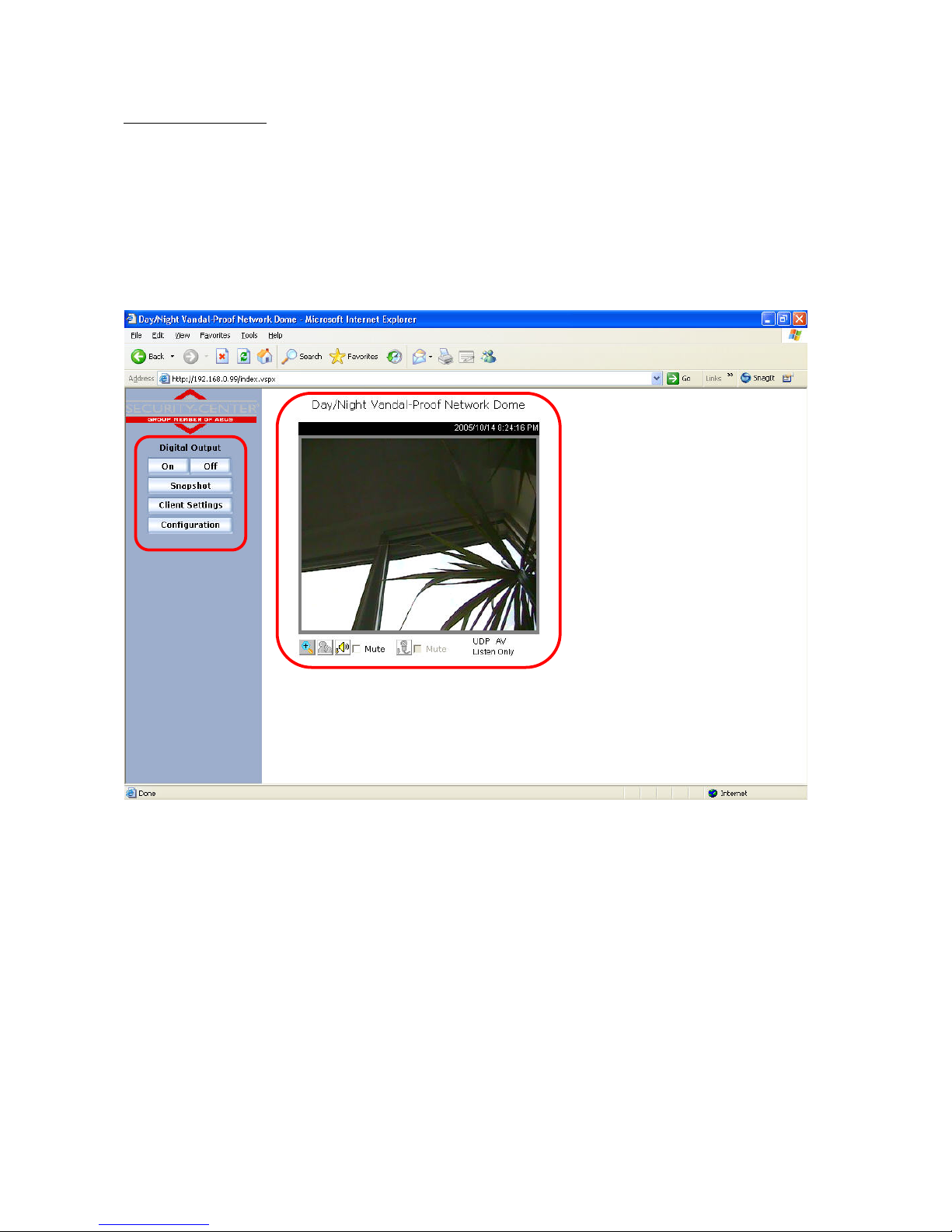
Main window and camera view
The view of the main page consists of two parts:
Configuration: The camera can be configured via this user interface.
Camera view: Camera video stream
Click the configuration link on the left of the picture to open the configuration page.
17
Configuration
Digital Output
Click
or to switch the relay output on/off.
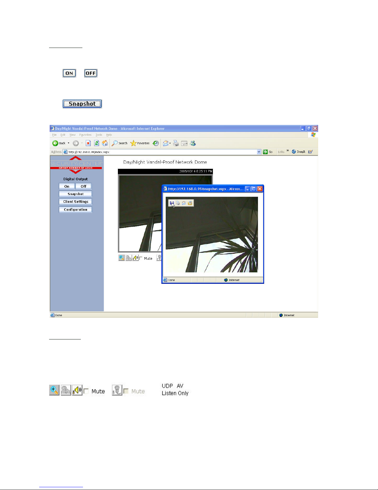
Snapshot
Click
. The web browser displays a new window containing the snapshot. To save the snapshot,
either left-click it and then click the diskette icon or right-click it and select Save from the context menu.
Camera view
The information bar at the top of the camera view shows the assigned caption and the current date/time. The
information bar at the bottom of the camera view shows the current streaming mode and audio transmission mode.
You can push/toggle the talk button to talk to the remote server. The volume of speaker and microphone can also
be adjusted.
Zoom
Click the magnifying glass under camera view. The control field for digital zooming appears. Disable the Disable
Digital Zoom box and change the zoom factor with the slider.
18
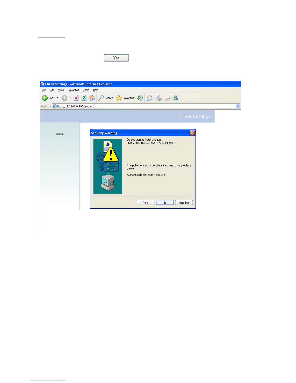
Client settings
When you first access the Connection Type page under Windows, the web browser asks for the installation of a new
plug-in. This plug-in was registered at certification and can be used to change parameters on the Client settings
page. To install the plug-in, click
. If the web browser prevents continuation of the installation, open
the Internet security settings and reduce the security level or consult the IT administrator or network administrator.
 Loading...